
As vehicle autonomy grows, the reliability of rearview camera systems has become a safety-critical necessity. Designing these systems requires selecting PCBs that can survive extreme temperature fluctuations, high vibration, and tight spatial constraints—all while ensuring zero-failure operation. This guide explores the strategic decisions required to build high-performance camera hardware that exceeds automotive industry standards.
The Evolution of Rearview Camera Systems and HDI Technology
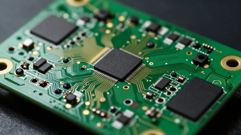
The Evolution from Analog to HDI-Enabled Digital Systems
The evolution of automotive rearview camera systems has moved from simple, bulky analog sensors to sophisticated digital arrays requiring extreme signal integrity. As the automotive industry mandates smaller footprints for driver assistance features, traditional rigid PCBs have struggled to balance heat dissipation with space constraints. HDI (High-Density Interconnect) technology bridges this gap by utilizing microvias, blind vias, and buried vias, allowing engineers to place components closer together while maintaining electrical performance.
Key Drivers for HDI Adoption in Automotive Imaging
The integration of CMOS image sensors with complex image signal processors (ISPs) requires high-speed data transmission that standard PCB fabrication cannot reliably support. HDI architecture reduces parasitic capacitance and inductance, which is critical for minimizing noise in high-resolution, high-frame-rate video feeds. Furthermore, the multi-layered HDI approach allows for better impedance control, ensuring that safety-critical visual data reaches the cabin display without latency.
Comparative Analysis: Traditional PCBs vs. HDI for Rearview Modules
| Feature | Traditional PCB | HDI PCB |
|---|---|---|
| Component Density | Low to Medium | Very High |
| Via Technology | Through-hole only | Microvias, Blind, Buried |
| Signal Integrity | Moderate | Excellent (Superior for High-Speed) |
| Size/Weight | Bulky | Compact and Lightweight |
Frequently Asked Questions
- Why is HDI essential for rearview cameras?
HDI allows for smaller camera housing sizes which are easier to integrate into aesthetic vehicle designs while accommodating more complex sensor processing circuitry. - Does HDI technology affect the heat profile of the camera?
Yes, by utilizing efficient thermal vias and shorter conductive paths, HDI layouts improve thermal management compared to standard boards, prolonging the life of the camera sensor. - Is HDI reliable for automotive environments?
When manufactured to IPC-6012 Class 3 standards, HDI boards provide exceptional mechanical and electrical reliability, even under extreme vibration and temperature fluctuations common in automotive applications.
Understanding AEC-Q Compliance and Reliability Standards
The Role of AEC-Q Standards in Automotive Electronics
In the automotive industry, standard commercial-grade components are insufficient to meet the rigors of long-term vehicular operation. AEC-Q (Automotive Electronics Council) standards serve as the industry benchmark for reliability, defining specific stress test qualifications that components must pass to be considered automotive-grade. For HDI PCBs integrated into rearview camera modules, adherence to these standards is not merely a preference; it is a fundamental safety requirement.
AEC-Q200 and Passive Component Reliability
AEC-Q200 specifically governs the qualification of passive components. Given that HDI boards utilize high-density surface-mount devices (SMDs) to shrink the footprint of camera image processors, the solder joint integrity between these passives and the PCB substrate is a common failure point. AEC-Q200 testing ensures that these connections resist thermal cycling, vibration, and humidity—conditions common in the exposed locations where rearview cameras are mounted.
| Requirement | Commercial Grade | AEC-Q Qualified |
|---|---|---|
| Temperature Range | 0°C to 70°C | -40°C to 125°C+ |
| Vibration/Shock | Standard Industrial | Automotive Severity (ISO 16750) |
| Failure Rate Target | Moderate | Near-Zero (Zero Defect Strategy) |
Key Reliability Considerations for HDI
- Why is thermal cycling critical for HDI boards?
HDI PCBs use complex via structures, including microvias. Rapid temperature changes cause differing rates of thermal expansion between the copper traces and the dielectric substrate, which can lead to micro-crack propagation if the board is not qualified to automotive standards. - How do AEC-Q standards prevent moisture-related failures?
Rearview cameras are subjected to external elements, including road spray and salt. AEC-Q testing mandates high-humidity and salt-mist exposure protocols to ensure the PCB surface finish and conformal coating provide adequate insulation resistance. - What is the consequence of non-compliance?
Using non-qualified components risks premature system failure, intermittent video feeds, and catastrophic sensor malfunctions, all of which pose significant safety liabilities and risk of recall.
Thermal Management Challenges in Compact Camera Modules
Thermal Management Challenges in Compact Camera Modules
As rearview camera modules shrink to meet aerodynamic and aesthetic automotive design requirements, the reduction in physical surface area limits natural convection, creating a significant thermal bottleneck. High-Density Interconnect (HDI) PCBs facilitate miniaturization but inherently concentrate power density. Without robust thermal management, heat buildup degrades electronic components, accelerates insulation aging, and can introduce image sensor noise, leading to critical safety system failures.
Thermal Dissipation Strategies for HDI Boards
Engineers must employ proactive heat mitigation strategies during the PCB layout phase. Key methods include the strategic use of copper weight, thermal via stitching, and the selection of high-Tg (glass transition temperature) dielectric materials to withstand localized hotspots without mechanical delamination.
| Strategy | Mechanism | Primary Benefit |
|---|---|---|
| Thermal Vias | Conductive channels connecting hotspots to ground planes | Reduces junction temperature |
| Copper Pouring | Maximizing ground plane copper area | Increases thermal mass and spreading |
| High-Tg Substrates | Selecting FR-4 materials with Tg > 170°C | Prevents board warpage and via cracking |
FAQs: Thermal Reliability in Automotive Imaging
- How do I prevent delamination in compact HDI boards?
Ensure the selected PCB laminate has a high Glass Transition Temperature (Tg) and a Coefficient of Thermal Expansion (CTE) that closely matches the copper circuitry to prevent mechanical stress during thermal cycling. - Are thermal vias enough for high-power sensors?
While essential, thermal vias should be paired with low-thermal-resistance interface materials (TIM) that bridge the PCB to the metal camera housing to act as a primary heat sink. - How does PCB layout impact image sensor performance?
Thermal instability induces dark current and thermal noise in CMOS sensors; keeping high-heat components isolated from the sensor area is critical for maintaining image fidelity.
Material Selection: Balancing Tg and CTE
The Thermal Balancing Act: Tg vs. CTE
In automotive rearview camera systems, the HDI PCB serves as the mechanical and electrical foundation within a compact, heat-intensive housing. The primary challenge is mitigating the mismatch between the PCB substrate's expansion and that of the copper traces and surface-mounted components. A high Glass Transition Temperature (Tg) ensures the dielectric remains rigid at operating temperatures, while a low Coefficient of Thermal Expansion (CTE), particularly in the Z-axis, is critical to prevent barrel cracking of microvias during continuous thermal cycling.
| Material Property | Requirement for Automotive HDI | Impact on Reliability |
|---|---|---|
| Glass Transition (Tg) | 170°C to 185°C | Prevents board softening and delamination. |
| Z-Axis CTE | < 3% (below Tg) | Reduces stress on microvias and solder joints. |
| Decomposition Temp (Td) | > 340°C | Ensures integrity during high-temp assembly. |
Material Selection Considerations
To achieve long-term reliability in vehicle environments, designers should prioritize halogen-free, high-Tg epoxy laminates that offer superior dimensional stability. These materials are engineered to resist the mechanical fatigue induced by rapid temperature shifts—such as moving from sub-zero winter temperatures to the heat of direct sunlight exposure.
- Why is Z-axis CTE critical for HDI?
As temperature increases, the PCB expands. If the Z-axis CTE is too high, the rapid expansion puts extreme tensile stress on microvias, leading to fractured interconnects and intermittent signal loss. - Can I use standard FR-4 for automotive cameras?
Standard FR-4 typically lacks the thermal stability and low CTE required for high-density applications. Automotive environments mandate specialized high-Tg materials that comply with the rigorous thermal shock requirements of AEC-Q200. - How does filler content affect material choice?
Modern high-performance laminates often utilize ceramic fillers to reduce CTE. Buyers should evaluate the filler type and percentage, as higher concentrations generally lead to lower CTE but can impact the dielectric constant (Dk) and loss tangent.
Optimizing Signal Integrity for High-Definition Video

As automotive rearview camera systems transition to high-definition (HD) output, maintaining signal integrity becomes the primary design constraint. In high-density interconnect (HDI) environments, compact routing leads to parasitic capacitance and electromagnetic interference (EMI), which can degrade video clarity. Successful implementation requires strict adherence to controlled impedance profiles and aggressive shielding strategies to manage high-speed differential pairs.
Strategies for Impedance Control in HDI
To prevent signal reflections that cause ghosting or data loss in video feeds, traces must maintain a consistent characteristic impedance—typically 100 ohms for differential pairs. Designers must optimize stack-up geometry and dielectric constants to ensure that high-speed signal lines remain stable across the entire transmission path.
| Design Factor | Impact on Signal Integrity | Recommended Action |
|---|---|---|
| Trace Geometry | Varies impedance significantly | Use laser-direct imaging for tighter tolerances |
| Dielectric Constant (Dk) | Affects propagation velocity | Specify materials with stable Dk over temperature |
| Via Placement | Causes signal discontinuities | Utilize micro-vias and back-drilling where applicable |
Mitigating EMI and Noise Coupling
Automotive environments are electromagnetically noisy. To protect delicate camera data streams, developers must implement robust ground planes and shielding structures.
- How do I isolate high-speed video signals from power noise?
Utilize a dedicated high-speed signal layer sandwiched between solid ground planes to provide an effective return path and prevent cross-talk. - What role does differential pair length matching play?
Strict length matching of P and N traces is essential to eliminate common-mode noise, ensuring the receiver can accurately reconstruct the differential signal. - Should I use guard traces for sensitive lines?
Yes, implementing ground-referenced guard traces provides an additional barrier against electromagnetic coupling in congested routing areas.
Vibration Resistance and Mechanical Durability
Vibration Resistance and Mechanical Durability
Automotive rearview cameras operate in high-vibration environments, subjecting PCBs to continuous mechanical stress that can lead to catastrophic solder joint fatigue and interlayer delamination. Selecting an HDI PCB requires a focus on structural rigidity and fatigue-resistant material systems that can withstand high-frequency oscillations without degrading electrical connectivity.
Key Mechanical Design Factors
| Design Element | Impact on Durability | Recommended Practice |
|---|---|---|
| Mounting Topology | Distributes stress across the board | Multi-point chassis mounting |
| Surface Finish | Influences solder joint integrity | Electroless Nickel Immersion Gold (ENIG) or ENEPIG |
| Copper Weight | Enhances structural stiffening | Use thicker internal foil for structural support |
| Component Placement | Minimizes leverage forces on joints | Place heavy components away from flex points |
Mitigating Solder Joint Fatigue
Solder joint fatigue is the primary failure mode in vehicle-mounted cameras. To prevent this, designers must prioritize the use of high-ductility solder alloys and optimized PCB surface finishes. Furthermore, ensuring that the CTE (Coefficient of Thermal Expansion) of the substrate remains closely matched to the surface-mounted components minimizes the shear stress exerted on joints during thermal-mechanical vibration cycles.
- How does PCB thickness influence vibration resistance?
Increased thickness enhances board stiffness, which raises the resonant frequency, reducing the amplitude of vibration and protecting sensitive micro-BGA solder connections. - Why is ENEPIG preferred over HASL for automotive HDI?
ENEPIG (Electroless Nickel Electroless Palladium Immersion Gold) provides a flatter, more reliable, and solder-joint-stable surface that is significantly more robust against repetitive mechanical shock compared to traditional HASL finishes. - What role do mounting points play?
Strategic mounting points act as nodal points, minimizing board deflection. Properly positioned screws or clips prevent the PCB from acting as a cantilevered beam, which would otherwise amplify vibrations.
Evaluating Supply Chain and Manufacturing Quality
Establishing a Quality Foundation
Selecting a PCB supplier for automotive rearview camera systems requires moving beyond price-point analysis toward a rigorous evaluation of manufacturing process control and quality assurance capabilities. The automotive environment demands zero-defect performance, necessitating partners that integrate automated optical inspection (AOI) and X-ray inspection at multiple stages of the HDI fabrication process.
Essential Certifications and Auditing
To ensure compliance with automotive industry standards, verify that your prospective manufacturer maintains active, updated certifications. These benchmarks serve as the minimum gateway for engagement.
- IATF 16949:2016
The global technical specification and quality management standard for the automotive industry; mandatory for all tier-one and tier-two suppliers. - IPC-6012 Automotive Addendum
Verification that the manufacturer adheres specifically to the automotive performance requirements for rigid printed boards, covering reliability beyond consumer-grade standards. - ISO 9001 and ISO 14001
Foundational standards for general quality management systems and environmental management, ensuring consistency in production outputs.
Comparative Metrics for Supplier Evaluation
| Quality Metric | Requirement | Buyer Expectation |
|---|---|---|
| Traceability | Full Lot Traceability | Ability to track material batches and production date codes. |
| Process Control | Statistical Process Control | Documentation of Cp/Cpk metrics for key HDI dimensions. |
| Failure Analysis | In-house Capability | Presence of micro-sectioning and thermal analysis labs. |
Ensuring Production Transparency
Transparency in the supply chain is non-negotiable for automotive rearview cameras. Reliable partners provide clear visibility into their sub-tier suppliers for copper, laminates, and chemical processes. A buyer should request periodic process capability reports that highlight defect rates, rework frequency, and yields, ensuring that the manufacturer is proactively addressing potential vulnerabilities in the HDI stack-up before they reach the assembly floor.
Future-Proofing Your Design for Next-Gen Automotive Tech
Designing for Architectural Scalability
As rearview cameras evolve from simple imaging devices into core nodes for ADAS sensor fusion, your PCB architecture must account for increasing data throughput and tighter latency requirements. Future-proofing necessitates a modular approach, where signal paths and power distribution networks are designed with overhead capacity, allowing for the transition from current LVDS standards to higher-bandwidth MIPI CSI-2 interfaces without requiring a complete redesign of the substrate.
Future-Proofing Considerations
- How does bandwidth headroom affect longevity?
Designing transmission lines for signal rates significantly higher than current requirements ensures your PCB can support future camera sensor upgrades without signal degradation or impedance mismatches. - Why prioritize software-defined hardware?
Utilizing programmable logic or modular interposers within the HDI design allows you to update image processing algorithms and communication protocols via firmware rather than hardware replacement. - What role does thermal management play?
Next-gen sensors often operate at higher clock speeds, generating more heat; integrating advanced thermal vias and high-Tg materials today prevents future thermal throttling constraints.
Technical Specifications Comparison
| Feature | Legacy Approach | Future-Proof Standard |
|---|---|---|
| Transmission Protocol | Standard LVDS | High-Speed MIPI CSI-2 |
| Material Tg | 130-150°C | 170°C+ |
| Impedance Tolerance | ±10% | ±5% |
| Layer Count | 4-6 Layers | 8+ Layers (HDI Any-Layer) |
Ultimately, selecting a manufacturer capable of producing Any-Layer HDI (AL-HDI) is the most effective way to secure future scalability. By enabling vertical connectivity between all layers, you gain the routing density necessary to integrate the advanced processing units and redundant power planes that tomorrow’s autonomous driving features will inevitably demand.
Selecting the right PCB is the foundation of a reliable and high-performing automotive rearview system. By focusing on thermal efficiency, compliance, and material performance, you can ensure your hardware stands the test of time. Ready to optimize your automotive PCB design? Contact our engineering team today to discuss your next project.
