
In the vertical transportation industry, the elevator controller is the heartbeat of the system. A single PCB failure can lead to catastrophic downtime or, worse, safety compromises. As engineering requirements for modern elevators become increasingly complex, selecting the right Printed Circuit Board hardware is no longer just a procurement task—it is a critical safety imperative. This guide provides an authoritative framework for navigating the technical and regulatory landscape of high-reliability PCB selection.
Understanding Mission-Critical Design Requirements
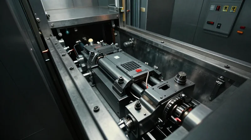
The Harsh Reality of Elevator Environments
Elevator control systems operate at the intersection of high-intensity mechanical stress and variable environmental conditions. Unlike standard industrial hardware, elevator PCBs must function reliably in shafts that experience significant temperature fluctuations, metallic dust accumulation, and persistent high-frequency vibrations. Designing for this context necessitates a departure from consumer-grade specifications toward automotive or industrial-grade reliability standards.
Environmental and Operational Stress Factors
| Stress Factor | Impact on PCB | Reliability Requirement |
|---|---|---|
| Thermal Cycling | Solder joint fatigue and delamination | High Tg (Glass Transition) materials |
| Vibration/Shock | Component displacement and trace cracking | Conformal coating and mechanical anchoring |
| Airborne Contaminants | Electrochemical migration and corrosion | Robust chemical-resistant coatings |
Key Reliability Considerations for Engineering Teams
- How do we mitigate solder joint failure in high-vibration shafts?
Engineers should specify components with heavier lead frame construction and utilize localized underfill or edge-bonding techniques to physically reinforce surface-mount packages against cyclical mechanical strain. - Why is the Glass Transition Temperature (Tg) critical?
A high Tg material prevents the board substrate from transitioning into a flexible, rubbery state during temperature spikes, which protects internal via structures from stress-induced fracture. - What role does conformal coating play in elevator longevity?
Conformal coatings act as a primary barrier against humidity and conductive dust, preventing short circuits caused by moisture condensation or metallic debris trapped within the control cabinet.
Ultimately, the selection process hinges on a design-for-reliability (DfR) mindset. By prioritizing substrate stability and contamination protection, manufacturers can ensure that elevator control systems meet the demanding lifecycle expectations of modern infrastructure.
Navigating Global Safety Standards and Compliance
Navigating Global Safety Standards and Compliance
Selecting a PCB for an elevator control system is not merely an engineering choice but a regulatory mandate. Because elevator safety is governed by strict international standards, your choice of substrate, components, and layout must comply with specific protocols designed to prevent catastrophic failure in public infrastructure.
Key Regulatory Frameworks
| Standard | Primary Region | Focus Area |
|---|---|---|
| ASME A17.1 | North America | Elevator & Escalator Safety Code |
| EN 81 | Europe | Safety rules for construction and installation |
| IEC 61508 | Global | Functional safety of electronic systems |
The Safety Integrity Level (SIL) rating is a measure of the relative risk-reduction provided by a safety function. For elevator controllers, which manage critical functions like emergency braking and door interlocks, designers should aim for SIL 2 or SIL 3 compliance. Achieving this requires the use of high-reliability components, redundant PCB trace routing, and rigorous failure mode and effects analysis (FMEA).
Compliance Frequently Asked Questions
- How does SIL impact PCB design?
SIL compliance necessitates fail-safe designs. This often requires redundant circuitry, isolation between safety-critical and non-critical logic, and the selection of AEC-Q or industrial-grade components with known MTBF metrics. - Is UL certification mandatory for elevator PCBs?
While local laws vary, UL 796 (Standard for Printed-Wiring Boards) is highly recommended for elevator applications to demonstrate fire resistance and electrical safety integrity to safety auditors. - What is the primary difference between EN 81 and ASME A17.1?
While both emphasize safety, ASME A17.1 is heavily prescriptive regarding mechanical safety, whereas EN 81 provides more specific guidance on the integration of programmable electronic systems (PESSRAL).
When sourcing PCBs, always verify that your manufacturer maintains ISO 9001 and IATF 16949 certifications. Documentation of the entire supply chain and adherence to lead-free (RoHS) standards are not just environmental concerns but indicators of the manufacturer's ability to maintain the high-quality standards required for safety-critical hardware.
Selecting High-Grade Materials for Thermal Stability
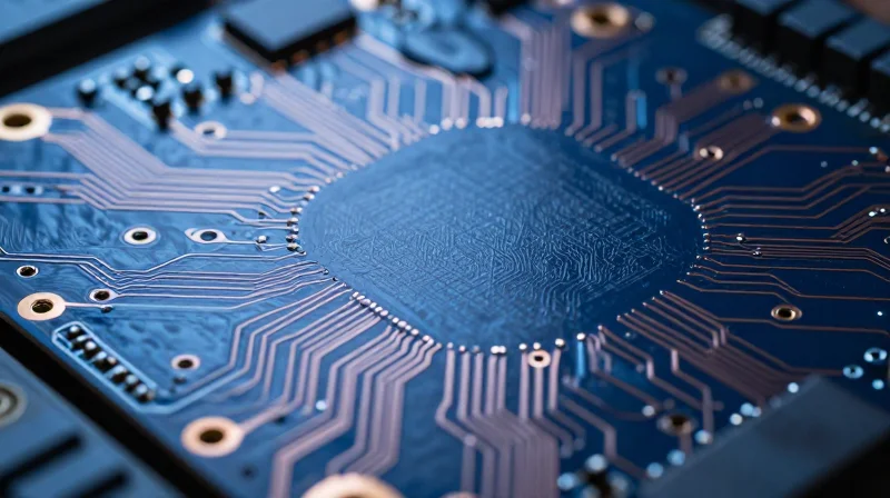
Evaluating Substrate Materials for Thermal Resilience
Elevator control systems often operate in machine rooms with limited ventilation, leading to high ambient temperatures and significant thermal cycling. Selecting the correct laminate material is the primary defense against delamination, board warping, and interconnect failure. Engineers must prioritize materials that offer low Coefficient of Thermal Expansion (CTE) and high thermal decomposition temperatures (Td) to maintain signal integrity over the 20+ year lifespan of the elevator equipment.
Substrate Material Comparison
| Material Type | Typical Tg (°C) | Suitability for Elevator Controls |
|---|---|---|
| Standard FR-4 | 130-140 | Low; prone to thermal stress failure. |
| High-Tg FR-4 | 170-180 | High; recommended for harsh environments. |
| Polyimide | >250 | Extreme; used for high-reliability/aerospace. |
Key Considerations for Thermal Stability
- What is the critical Tg threshold?
For elevator systems, a Glass Transition Temperature (Tg) of at least 170°C is generally considered the minimum baseline to prevent substrate transition from a rigid to a rubbery state during thermal excursions. - Why is CTE (Coefficient of Thermal Expansion) mismatch dangerous?
When the CTE of the copper traces differs significantly from the substrate material, thermal cycling can cause plated-through-hole (PTH) cracking, leading to intermittent signal failures or total system shutdown. - How does Td (Decomposition Temperature) impact reliability?
The Td indicates the temperature at which the material starts to chemically degrade. Using materials with a high Td ensures the board can withstand the extreme heat involved in soldering and intense electrical loading without delamination.
Beyond selecting the right base laminate, ensure that your fabrication partner provides detailed thermal stress testing reports. Specifying a material with consistent resin distribution is also vital for preventing localized hotspots that can prematurely weaken board structure near high-power drive components.
Signal Integrity and Electromagnetic Compatibility (EMC)
Minimizing Electromagnetic Interference (EMI)
In elevator control systems, high-frequency switching and proximity to high-voltage motors generate significant electromagnetic noise. To maintain signal precision, engineers must adopt a multilayer PCB stackup strategy. Placing critical signal layers between continuous ground planes provides essential shielding, while maintaining short, controlled-impedance traces minimizes the loop area for potential interference.
| Design Strategy | Primary Benefit | Implementation Priority |
|---|---|---|
| Differential Signaling | Noise immunity via common-mode rejection | High |
| Solid Ground Planes | Reduced return path impedance | Critical |
| Via Stitching | Enhanced edge-shielding and EMI containment | Medium |
Best Practices for PCB Layout and Grounding
Proper grounding is the most effective deterrent against EMI. A star-grounding architecture should be implemented to prevent ground loops, which are notorious for injecting noise into sensitive analog sensor data. Additionally, separating high-speed digital circuitry from sensitive analog lines through physical board zoning prevents crosstalk and maintains the integrity of encoder inputs.
Frequently Asked Questions
- How does via stitching affect EMC?
Via stitching along board edges creates a Faraday cage effect, containing radiated emissions within the PCB substrate and preventing coupling with external wiring. - Why is differential signaling preferred for encoder feedback?
Differential signaling uses two complementary lines to transmit data, allowing the system to cancel out external common-mode noise, which is vital for long elevator shaft cable runs. - Is galvanic isolation necessary?
Yes, implementing optocouplers or digital isolators between the high-voltage motor control stage and low-voltage logic ensures that transient surges cannot propagate into the main controller.
Advanced Component Longevity and Obsolescence Management
Strategies for Mitigating Component Obsolescence
Elevator control systems must remain operational for decades, often outlasting the availability of specific electronic components. To ensure long-term maintainability, engineers must move beyond standard procurement and adopt a proactive lifecycle management strategy that prioritizes supply chain resilience.
- Adopt Lifecycle-Aware Design
Select components with long-standing production histories, often labeled as 'industrial grade' or 'long-life' by major manufacturers to guarantee 10-20 year availability. - Implement Last-Time Buy (LTB) Programs
Monitor Product Change Notifications (PCNs) and End-of-Life (EOL) alerts to execute strategic inventory acquisition before primary manufacturing ceases. - Prioritize Architecture Agnostic Designs
Design modular PCB architectures where individual modules can be swapped or upgraded without requiring a full system redesign if a legacy component becomes unavailable.
Comparison of Lifecycle Mitigation Approaches
| Strategy | Primary Benefit | Risk Factor |
|---|---|---|
| Component Emulation | Maintains legacy firmware | High development cost |
| Strategic Stockpiling | Immediate availability | Inventory holding cost |
| Platform Redesign | Uses latest technology | Extensive re-certification |
Frequently Asked Questions
- How often should I monitor EOL notices for elevator PCBs?
Monthly monitoring is recommended. Automated tools that track PCNs against your current Bill of Materials (BOM) are superior to manual reviews. - Is it better to stockpile or redesign when a component goes EOL?
Stockpiling is preferred for near-term fixes (1-3 years), while redesigning is necessary if the component is core to safety-critical logic that must last another decade.
PCB Fabrication and Assembly Quality Controls
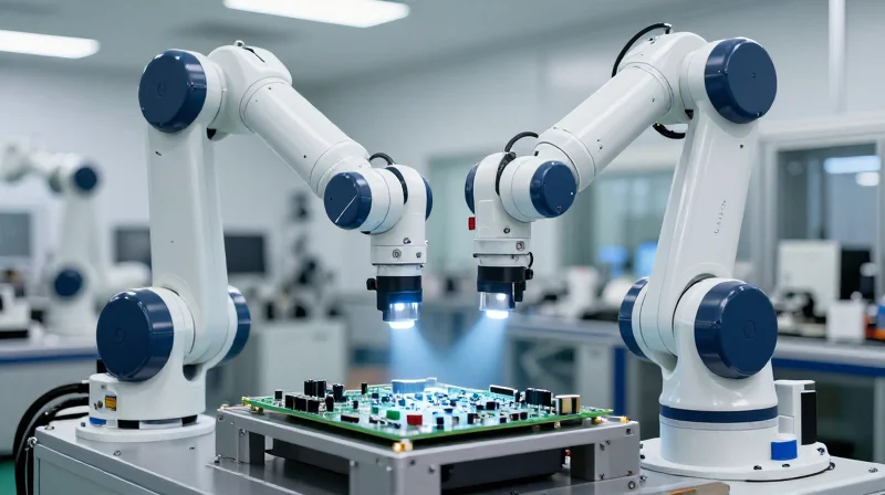
For elevator control systems, where safety is non-negotiable, PCB quality control extends beyond simple visual inspection. High-reliability manufacturing mandates a multi-layered testing regime that catches manufacturing defects—such as solder bridging, open circuits, or hidden voids—before the board reaches the field. Engineering teams must demand rigorous adherence to IPC-Class 3 standards to ensure long-term survivability in high-vibration and fluctuating temperature environments.
Essential Inspection and Testing Methodologies
| Testing Method | Primary Application | Detection Capability |
|---|---|---|
| AOI (Automated Optical Inspection) | Surface Component Placement | Missing parts, polarity, and solder fillets |
| AXI (Automated X-Ray Inspection) | BGA/Hidden Solder Joints | Internal voids, shorts, and BGA bridging |
| Flying Probe Testing | Bare Board / Populated | Open circuits, shorts, and component values |
| ICT (In-Circuit Testing) | High-Volume Assembly | Electrical function and component tolerance |
Quality Assurance Best Practices
- IPC-Class 3 Compliance
Always mandate IPC-6012 Class 3 or IPC-A-610 Class 3 for elevator systems to ensure stricter acceptance criteria for solder joints and internal board integrity. - Traceability Protocols
Ensure the manufacturer provides full material traceability, allowing you to track individual components and substrate batches back to the original source. - Thermal Cycling Verification
Conduct post-assembly thermal shock testing to validate that interconnections remain robust under the rapid temperature transitions typical of hoistway operations.
Frequently Asked Questions
- Is Flying Probe enough for complex boards?
While efficient for prototypes and complex designs, Flying Probe lacks the high-throughput capabilities and hidden-joint visibility that AXI provides for dense BGA-heavy boards. - Why is AXI mandatory for elevator controllers?
Many modern microcontrollers use BGA packages with hidden pads. AXI is the only reliable way to detect sub-surface solder voids that could lead to intermittent failures in the field.
Designing for Maintainability and Serviceability
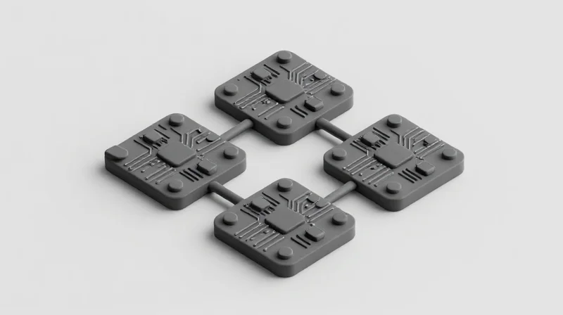
Implementing Modular Architecture for Rapid Field Maintenance
High-reliability elevator control systems should utilize a modular board-to-board design strategy. By isolating critical functions—such as motor control, safety interlocks, and communication gateways—onto distinct, swappable PCB modules, engineers can replace localized failures without requiring a full system decommission. This approach ensures that MTTR (Mean Time to Repair) is significantly reduced by allowing technicians to swap out faulted sub-assemblies in the field.
Diagnostic Accessibility and Serviceability Features
Effective design for serviceability necessitates that diagnostic data is readily available to the technician on-site. Integrating onboard hardware-based diagnostics allows for immediate status verification.
- Visual Status Indicators
Implement high-visibility LED arrays to indicate power rail stability, communication link status, and safety string continuity directly on the PCB silkscreen. - External Diagnostic Ports
Include hardened JTAG or localized CAN-bus diagnostic headers that do not require specialized proprietary tools, facilitating standard laptop interfacing for firmware debugging. - Keying and Polarization
Utilize polarized connectors to prevent incorrect assembly or forced insertion, protecting the control system from accidental damage during stressful field repair scenarios.
Comparison: Traditional Monolithic vs. Modular Serviceability
| Feature | Monolithic PCB | Modular PCB Design |
|---|---|---|
| Field Repairability | Board Replacement Required | Component/Module Swap |
| Diagnostic Complexity | High (Requires Schematics) | Low (Status LEDs/Buses) |
| Mean Time to Repair (MTTR) | Extended | Minimal |
| Risk of Secondary Damage | High during desoldering | Negligible |
To achieve high maintainability, prioritize the placement of high-failure-rate components, such as electrolytic capacitors or relays, in easily accessible areas of the PCB layout. Avoid placing critical surface-mount diagnostic points under heavy heatsinks or rigid shielding, as this obstructs rapid signal probing during critical system outages.
Evaluating Supplier Capabilities and Vendor Partnership
Evaluating Quality Management Systems (QMS)
For elevator control applications, a manufacturer's QMS is not just a certification; it is a promise of process control and failure mitigation. You must look beyond standard ISO 9001 compliance to ensure the partner understands the specific safety-critical requirements of the elevator industry.
| Certification | Relevance to Elevator PCBs | Key Benefit |
|---|---|---|
| ISO 9001 | Foundational Quality | Standardized process management. |
| IATF 16949 | Advanced Automotive | Enhanced defect prevention and supply chain variation reduction. |
| AS9100 | Aerospace/Defense | Extreme traceability and rigorous risk management. |
Technical Support and Collaborative Engineering
A reliable partner functions as an extension of your engineering team. In high-reliability elevator design, manufacturer involvement during the DFM (Design for Manufacturing) phase is crucial to prevent latent defects that standard inspections might miss.
- How do I assess a vendor's DFM capability?
Request a sample DFM report on a recent complex design they completed. Evaluate their ability to provide actionable feedback on stack-up optimization, copper balancing, and thermal management. - Why is technical local support critical?
Real-time communication during the prototype phase allows for rapid design adjustments that save months of cycle time and ensure compliance with regional elevator safety standards. - What transparency should be expected?
A high-reliability partner should provide full material traceability, including C of C (Certificate of Conformance) for raw laminates and process logs for every batch produced.
Vetting Long-Term Vendor Stability
Elevator systems often remain in service for 20+ years. Your PCB partner must demonstrate financial stability and a robust supply chain to support long-term component lifecycle management, preventing the need for costly board redesigns due to unexpected vendor insolvency or component obsolescence.
Selecting the right PCB for elevator controllers is a rigorous balance of regulatory compliance, environmental durability, and long-term component availability. By prioritizing these engineering standards, you ensure the safety of passengers and the longevity of the entire elevator infrastructure. If you are currently sourcing hardware for your next project, contact our team of experts today to discuss your specific design requirements and ensure your next controller meets the highest safety benchmarks.
