
In the race for brighter, more efficient lighting, thermal management is the silent gatekeeper of success. As high-power LED applications push physical boundaries, standard FR4 substrates often fail under intense thermal stress. Choosing the right ceramic PCB is no longer just a design preference—it is a critical engineering decision that dictates the reliability and long-term viability of your lighting solution.
The Critical Role of Thermal Conductivity in LED Longevity
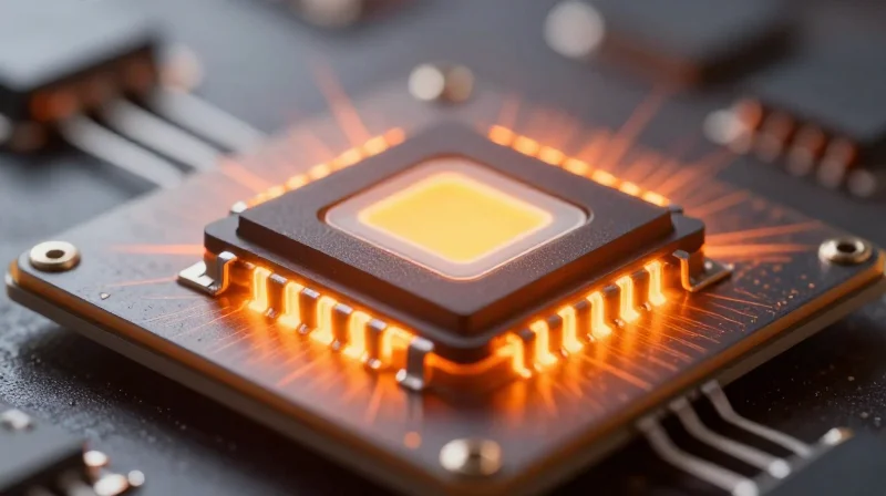
The Thermal Management Imperative
In high-power LED systems, thermal management is not merely a design feature but the primary determinant of service life. As electrical current increases to meet brightness demands, a significant portion of energy is converted into heat rather than light. If this heat is not efficiently moved away from the LED junction through the PCB substrate, the junction temperature (Tj) spikes, leading to immediate color shifting, phosphor degradation, and catastrophic diode failure.
Substrate Conductivity Comparison
| Material Type | Thermal Conductivity (W/mK) | Suitability for High-Power LED |
|---|---|---|
| Standard FR-4 | 0.25 | Poor |
| Alumina (Al2O3) | 20 - 30 | Moderate |
| Aluminum Nitride (AlN) | 170 - 230 | Excellent |
| Silicon Carbide (SiC) | 120 - 200 | Excellent |
Common Thermal Management Queries
- Why is ceramic superior to metal-core PCBs for high-power LEDs?
Ceramic offers a higher thermal conductivity combined with inherent electrical insulation, eliminating the need for bulky, thermally resistive dielectric layers found in standard metal-core boards. - How does substrate thermal conductivity influence junction life?
Every 10°C increase in operating junction temperature can effectively halve the expected lifespan of an LED; high-conductivity substrates ensure the heat path is short and efficient. - Is higher thermal conductivity always better?
While higher values are generally safer, one must balance conductivity with mechanical properties, cost, and the thermal expansion matching required to avoid solder joint fatigue.
Analyzing Dielectric Constant and Signal Integrity

The Impact of Dielectric Constant (Dk) on Signal Integrity
The dielectric constant (Dk) is a measure of a material's ability to store electrical energy in an electric field. For high-performance ceramic PCBs, maintaining a stable and low Dk is vital for controlling impedance and minimizing signal propagation delay. As high-power LEDs increasingly incorporate integrated control circuitry and high-frequency PWM dimming, the substrate must provide a consistent electrical environment to prevent signal distortion and crosstalk.
Key Dielectric Metrics for Performance Evaluation
| Metric | Significance | High-Performance Target |
|---|---|---|
| Dielectric Constant (Dk) | Affects impedance and velocity | Low and stable across frequencies |
| Dissipation Factor (Df) | Indicates signal loss/heating | Extremely low (< 0.005) |
| Dk Stability | Consistency vs. temperature | Minimal shift (+/- 0.02) |
Mitigating Signal Loss through Dissipation Factor
The dissipation factor (Df), or loss tangent, represents the portion of electromagnetic energy lost as heat within the dielectric material. In high-power LED systems, a high Df can lead to unwanted dielectric heating, which compounds the thermal load already generated by the LED junction. Choosing ceramics with a low Df ensures that signal integrity remains intact even when operating at elevated temperatures or higher switching frequencies.
Frequently Asked Questions on Dielectric Stability
- Why is a stable Dk important for LED driving?
A stable Dk ensures that impedance remains constant, preventing signal reflections that can degrade the performance of high-speed LED dimming protocols and communication interfaces. - How does ceramic material choice influence Df?
Ceramics like Alumina or Aluminum Nitride offer naturally superior dielectric properties compared to organic laminates like FR-4, providing significantly lower loss tangents even under harsh thermal stress. - Does frequency affect the dielectric constant?
Yes, many materials exhibit 'dispersion,' where the Dk value shifts with frequency. High-performance ceramic substrates are engineered to maintain a flat Dk curve to ensure predictable electrical behavior across a wide bandwidth.
Comparing Aluminum Nitride vs. Alumina Substrates
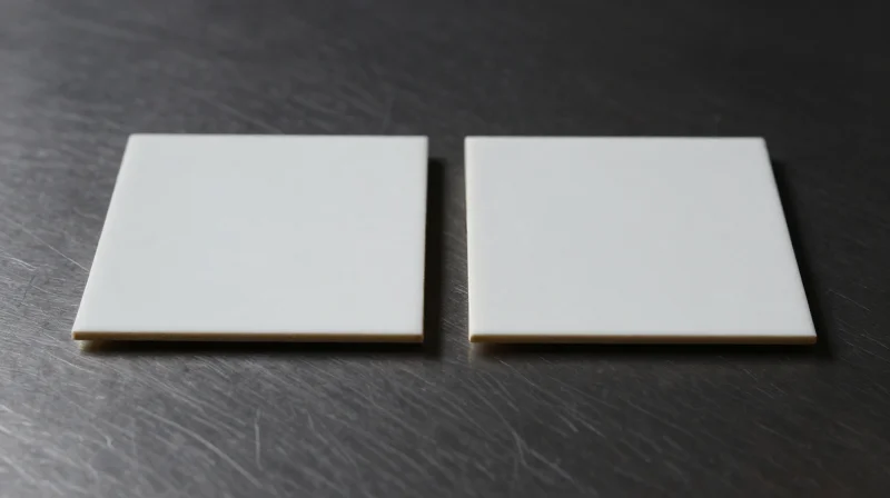
Thermal Dynamics and Material Selection
Selecting the optimal substrate requires a precise balance between thermal dissipation requirements and project budget constraints. While Alumina (Al2O3) serves as the industry standard for general lighting, Aluminum Nitride (AlN) is the superior choice for high-density, high-power LED arrays due to its exceptional thermal conductivity.
| Property | Alumina (Al2O3) | Aluminum Nitride (AlN) |
|---|---|---|
| Thermal Conductivity | 20-30 W/m·K | 170-230 W/m·K |
| Cost Efficiency | High | Low |
| CTE Match to Si | Moderate | Excellent |
| Primary Application | Standard Power LEDs | High-Power/Automotive |
When to Choose Alumina (Al2O3)
Alumina remains the workhorse of the ceramic PCB industry. It offers a reliable dielectric constant and mechanical strength at a fraction of the cost of advanced nitrides. For LEDs where thermal density is moderate, Alumina provides sufficient heat spreading to prevent premature junction degradation while keeping BOM costs within competitive limits.
When to Choose Aluminum Nitride (AlN)
Aluminum Nitride is non-negotiable for ultra-high-power density applications. With thermal conductivity nearly ten times that of Alumina, AlN effectively acts as a thermal heat spreader, reducing the risk of catastrophic junction failure in compact LED modules. It is the preferred substrate for aerospace, automotive, and industrial laser-diode cooling.
Decision-Making FAQ
- Can AlN replace Al2O3 in existing designs?
Yes, but you must account for the mechanical property differences and the significantly higher unit cost which may impact project profitability. - Does CTE matching matter for LED longevity?
Yes. AlN has a Coefficient of Thermal Expansion closer to Silicon than Al2O3, which reduces mechanical stress during thermal cycling, thereby extending the life of the solder joints.
Coefficient of Thermal Expansion (CTE) Matching
The Mechanics of CTE Mismatch in High-Power LEDs
Coefficient of Thermal Expansion (CTE) defines how a material changes its physical dimensions in response to temperature fluctuations. In high-power LED applications, the LED die, the solder interconnect, and the ceramic substrate must expand and contract at compatible rates. When these materials have significantly different CTE values, cyclic thermal loading—caused by power cycling the LED—generates high mechanical stress at the interface. Over time, this stress manifests as micro-cracks in the solder joints and potential delamination of the die-attach material, leading to increased thermal resistance and eventual device failure.
Comparative CTE Profiles of Common Materials
| Material | Approx. CTE (ppm/°C) | Suitability for High-Power LED |
|---|---|---|
| GaN/Sapphire Die | 5.0 - 7.5 | Baseline Reference |
| Alumina (Al2O3) | 6.5 - 7.2 | Excellent Match |
| Aluminum Nitride (AlN) | 4.5 - 5.0 | Good Match (with stress buffers) |
| Copper (Heat Sink) | 16.5 - 17.0 | High Mismatch Potential |
Mitigating CTE-Induced Failure
- What happens when CTE is not matched?
Persistent mismatch creates shear stress on the solder joints, resulting in brittle fractures that compromise both electrical continuity and thermal path efficiency. - How does ceramic selection influence CTE stability?
Ceramics like Alumina offer a native CTE closely aligned with semiconductor materials, reducing the reliance on compliant bond-line materials to manage thermal expansion stresses. - Can thermal interface materials (TIM) compensate for mismatch?
While specialized ductile TIMs can absorb some strain, relying on them as a primary solution for poor CTE matching is discouraged, as they often exhibit lower thermal conductivity than direct ceramic-to-die attachment.
Engineers designing high-performance LED systems must prioritize materials that demonstrate high thermal conductivity alongside CTE values within the 4-8 ppm/°C range to ensure long-term structural integrity in harsh operating environments.
Surface Finish Options for Enhanced Light Reflection
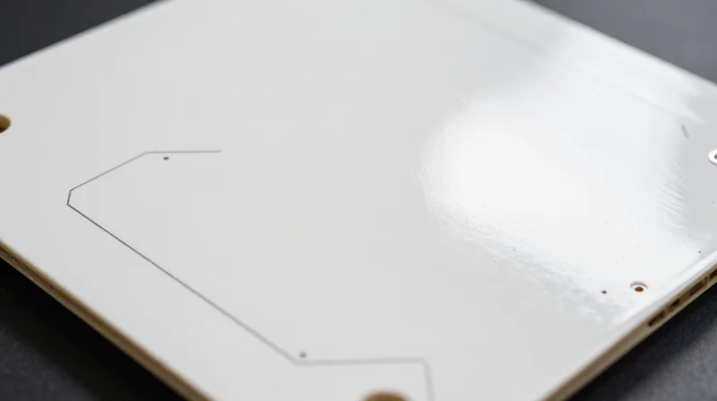
The surface finish of a ceramic PCB serves as the critical interface between the high-power LED chip and the substrate, directly influencing light reflection, thermal contact, and electrical connectivity. For high-lumen applications, the reflective index of the finish is paramount to minimizing optical loss, while wire bond integrity remains essential for preventing premature device failure due to thermal cycling.
Comparative Analysis of Surface Finishes for LED Reflectivity
| Surface Finish | Reflectivity (Visible Light) | Wire Bonding Capability | Primary Application |
|---|---|---|---|
| Electroless Silver (Ag) | Very High (>95%) | Excellent | High-power LED arrays |
| Electroless Gold (ENIG/ENEPIG) | Moderate | Superior | Precision control electronics |
| Electroless Nickel (EN) | Low | Good | Thermal mounting only |
Key Considerations for Selection
- Why is silver preferred for high-brightness LEDs?
Silver offers the highest initial reflectivity among industry-standard finishes, significantly improving light extraction efficiency. However, it requires careful handling to prevent sulfidation in high-humidity environments. - Does gold finish impact lumen output?
While gold provides excellent corrosion resistance and wire bonding, its lower reflectivity compared to silver can reduce total luminous flux, making it more suitable for back-plane contact areas than direct light-reflection zones. - How does ENEPIG affect reliability?
Electroless Nickel Electroless Palladium Immersion Gold (ENEPIG) provides a multi-layer barrier that prevents nickel migration and creates an extremely stable surface for gold-wire bonding, crucial for high-power thermal stability.
Optimizing for Longevity
Selecting the finish should balance optical requirements with the expected operating environment. For demanding automotive or industrial lighting, ENEPIG is often recommended for its superior resistance to thermal fatigue and oxidation. Conversely, when the design prioritizes raw lumen output above all other metrics, high-purity silver remains the industry standard, provided that the PCB design incorporates appropriate sealing to protect against environmental degradation.
Navigating Industry Standards and Regulatory Compliance
Navigating Industry Standards and Regulatory Compliance
Selecting a high-performance ceramic PCB for high-power LED applications requires more than just thermal and electrical optimization; it demands rigorous adherence to global industry standards. Compliance ensures that your lighting hardware remains safe, reliable, and marketable across international borders. Engineers must prioritize substrates and manufacturing processes that meet established IPC and ISO benchmarks to mitigate liability and ensure long-term field stability.
Essential Industry Standards for LED PCBs
| Standard | Focus Area | Application Relevance |
|---|---|---|
| IPC-6012 | Rigid PCB Performance | Defines structural integrity and thermal reliability of ceramic boards. |
| ISO 9001 | Quality Management | Ensures consistent manufacturing quality for high-volume LED production. |
| UL 94-V0 | Flammability Rating | Critical for high-power thermal safety in LED enclosures. |
| RoHS/REACH | Environmental Compliance | Restricts hazardous materials in PCB surface finishes and solders. |
Frequently Asked Questions on Compliance
- Why is the UL 94-V0 rating critical for ceramic LED PCBs?
High-power LEDs operate at elevated temperatures; a V0 rating ensures the substrate will self-extinguish quickly in the event of an electrical fault, preventing fire propagation. - How does IPC-6012 apply to ceramic substrates?
IPC-6012 outlines the quality requirements for rigid PCBs. For ceramics, it specifically governs the integrity of metal-to-ceramic interfaces and plating thickness to prevent delamination under thermal cycling. - Does RoHS compliance affect light reflection quality?
Modern RoHS-compliant surface finishes like Immersion Silver (ImAg) or Electroless Nickel Immersion Gold (ENIG) provide excellent light reflectivity and oxidation resistance without using restricted heavy metals.
To guarantee compliance, always request a Certificate of Conformance (CoC) from your PCB fabricator. Verify that the testing laboratory is ISO/IEC 17025 accredited, ensuring that the thermal conductivity and dielectric strength data provided for your ceramic substrate are verified by third-party protocols.
Prototyping and Thermal Simulation Best Practices
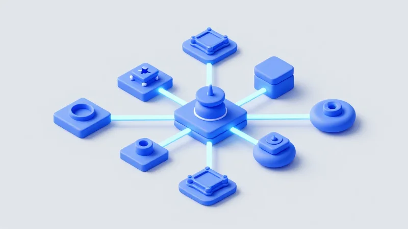
The Role of Thermal Simulation in Design Validation
Before finalizing a ceramic PCB design, engineers must utilize Finite Element Analysis (FEA) and Computational Fluid Dynamics (CFD) to predict heat dissipation pathways. By simulating the thermal resistance of the ceramic substrate and the interface materials, you can identify potential hot spots that would otherwise lead to premature diode failure or phosphor degradation in a real-world environment.
Best Practices for Prototyping
- Simulate Early and Often
Integrate thermal modeling during the initial layout phase rather than as a post-design check to minimize the cost of geometric changes. - Account for Boundary Conditions
Ensure your model includes real-world heat sinks, ambient temperature fluctuations, and air convection paths, as idealized models often underestimate peak junction temperatures. - Validate with Physical Prototypes
Perform IR thermography on your first prototype batch to correlate actual surface temperatures against your simulated data sets.
Comparing Simulation Methods
| Simulation Method | Primary Benefit | Best Use Case |
|---|---|---|
| Simplified FEA | Rapid iterative feedback | Early-stage material selection |
| Full CFD | Precise airflow modeling | Final thermal system validation |
| IR Thermography | Real-world data validation | Post-prototype debugging |
Common Prototyping Challenges
- Why do simulations often differ from reality?
Discrepancies often arise from inaccurate Thermal Interface Material (TIM) thickness assumptions or neglected contact resistance at the ceramic-to-heatsink interface. - How can I improve simulation accuracy?
Use actual measured thermal conductivity values for your specific ceramic grade (e.g., AlN vs. Al2O3) rather than generic industry averages.
Cost-to-Performance Ratio: Making the Final Selection
Strategic Financial Justification
Selecting the right ceramic PCB is not merely about finding the lowest unit price, but calculating the Total Cost of Ownership (TCO). While Aluminum Nitride (AlN) offers superior thermal conductivity, it comes at a premium that may be excessive for mid-range LED arrays. Conversely, Alumina (Al2O3) provides a cost-effective baseline that, when optimized with high-quality metalization, often satisfies the thermal demands of standard high-power lighting without the significant cost overhead of advanced ceramics.
| Material | Thermal Conductivity (W/mK) | Relative Cost | Best Application Case |
|---|---|---|---|
| Alumina (Al2O3) | 20-30 | Low | General high-power lighting |
| Aluminum Nitride (AlN) | 170-230 | High | Industrial/High-density UV LEDs |
| Silicon Nitride (Si3N4) | 60-90 | Very High | Mechanical-load heavy environments |
Optimizing Cost Through Design
Design efficiency often dictates the final price more than material selection itself. By minimizing board dimensions, utilizing standard panel sizes to reduce waste, and selecting standard thicknesses, engineers can significantly reduce fabrication costs. Focus on integrating thermal features into the substrate design rather than relying on oversized ceramic footprints, which inflate material costs.
Frequently Asked Questions on Cost Optimization
- Does a higher thermal conductivity always justify the higher cost?
No. If your LED junction temperature remains within safety limits using a lower-cost Alumina substrate, paying for AlN provides diminishing returns and increases project overhead unnecessarily. - How does surface finish affect the final project budget?
Electroless Nickel Immersion Gold (ENIG) is generally more expensive than Electroless Silver. Choose surface finishes based on reflectivity and wire-bonding requirements; over-specifying a finish increases costs without guaranteeing performance. - Can I mix materials in a multi-layered design?
Yes, though it increases complexity. Often, it is more cost-effective to use a high-thermal-conductivity core in specific heat-concentrated zones rather than using high-performance ceramic throughout the entire PCB stackup.
Selecting the right ceramic PCB is the bridge between a prototype that flickers and a lighting system that lasts for years. By focusing on thermal conductivity, CTE compatibility, and material precision, you can guarantee superior performance for your high-power LEDs. Ready to optimize your lighting design? Contact our engineering team today for a comprehensive thermal analysis of your next project.
