
In the demanding world of industrial lighting, the difference between a long-lasting LED driver and a premature failure often lies in the substrate. As thermal loads increase, traditional FR-4 materials fall short. Selecting the right Metal Core PCB (MCPCB) is no longer just a design choice—it is a critical engineering decision that dictates the lifespan of your infrastructure. This guide dissects the technical requirements needed to achieve superior thermal management and structural reliability.
Understanding the Role of Aluminum PCBs in Thermal Dissipation
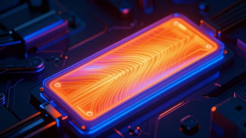
The Physics of Thermal Management in LED Drivers
Industrial LED drivers operate under high current densities that generate significant waste heat. If not effectively dissipated, this thermal energy elevates the junction temperature (Tj) of the LED, leading to phosphor degradation, shifts in chromaticity, and eventual catastrophic failure of the semiconductor. Aluminum PCBs serve as a high-performance thermal bridge, utilizing a Metal Core Printed Circuit Board (MCPCB) architecture to provide a direct, low-resistance path from the heat source to the ambient environment.
Why Aluminum Substrates Outperform FR4
In standard FR4 laminates, the dielectric constant and thermal conductivity are insufficient for high-wattage LED applications. Aluminum acts as a heat sink foundation, offering thermal conductivity ratings typically between 1.0 W/mK and 3.0 W/mK for the dielectric layer, compared to the near-insulating properties of standard fiberglass epoxy. This structural difference enables the rapid lateral spreading of heat across the entire board surface.
| Feature | FR4 Substrate | Aluminum Substrate (MCPCB) |
|---|---|---|
| Thermal Conductivity | 0.25 - 0.3 W/mK | 1.0 - 3.0+ W/mK |
| Thermal Expansion | High (Mismatch with LED) | Low (Engineered Compatibility) |
| Heat Dissipation | Slow / Concentrated | Rapid / Distributed |
| Ideal Application | Control Logic | High-Power LED Lighting |
Common Considerations for Thermal Design
- How does the dielectric thickness impact thermal resistance?
A thinner dielectric layer minimizes the distance heat must travel through the insulating material, thereby reducing thermal impedance and increasing total heat transfer efficiency. - What role does the aluminum base thickness play?
While the base thickness provides structural rigidity, its primary role is to serve as a high-surface-area heat spreader; thicker bases offer more thermal mass to buffer transient temperature spikes in industrial environments. - Is thermal interface material (TIM) necessary?
Yes, even with an aluminum PCB, a high-quality TIM is required to eliminate microscopic air gaps between the aluminum base and the secondary heatsink, ensuring seamless thermal coupling.
Evaluating Thermal Conductivity Ratings (W/mK)
Thermal conductivity, measured in Watts per meter-Kelvin (W/mK), defines the dielectric layer's ability to transfer heat from the LED junction to the aluminum base. In high-power industrial LED drivers, failing to match the W/mK rating to the heat load leads to thermal throttling, shortened component lifespan, and potential premature failure of sensitive surface-mount devices.
The Impact of W/mK on Heat Dissipation
Standard thermal management strategies often default to specific dielectric materials based on power density. While a 1.0 W/mK rating may suffice for standard consumer-grade applications, high-density industrial drivers often require 2.0 to 3.0 W/mK or higher to maintain junction temperatures within safe operating limits.
| Thermal Conductivity (W/mK) | Ideal Application Type | Thermal Performance Level |
|---|---|---|
| 1.0 - 1.5 | Low-power architectural lighting | Basic |
| 2.0 - 2.5 | Industrial floodlights, Street lighting | Intermediate |
| 3.0+ | High-power stadium or heavy industrial arrays | High-Efficiency |
Selecting the Optimal Rating for Your Design
- How does power density dictate the W/mK choice?
Higher power densities require materials with lower thermal resistance to prevent hotspots; as the power per square inch increases, the dielectric must have a higher W/mK to move heat away efficiently. - Is higher W/mK always better?
Not necessarily. Higher conductivity materials often carry a significant cost premium and may have different structural properties that affect mechanical rigidity. Over-engineering thermal conductivity when not required is a common cause of unnecessary manufacturing overhead. - What role does the dielectric thickness play?
Thermal resistance is a function of both the thermal conductivity and the thickness of the layer; a very thin dielectric with a lower W/mK can sometimes outperform a thicker dielectric with a higher W/mK.
Engineers should perform a thermal analysis using finite element modeling (FEM) during the prototype phase. By simulating the expected heat flux, you can verify if a specific W/mK material maintains the LED junction temperature below the manufacturer’s recommended threshold, typically between 85°C and 105°C, ensuring optimal performance under continuous industrial load.
Dielectric Strength and Breakdown Voltage
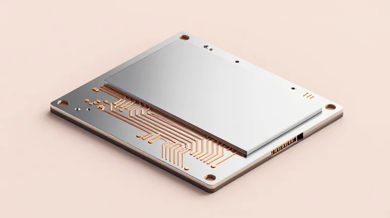
The Role of the Dielectric Layer in Electrical Isolation
In an Aluminum PCB (MCPCB), the dielectric layer serves as the thin, thermally conductive, and electrically insulating interface between the copper circuit layer and the aluminum base. For industrial LED drivers, which often operate in harsh environments with voltage spikes and high power densities, the integrity of this layer is the primary defense against electrical shorts and dielectric breakdown. Selecting a material with inadequate dielectric strength can lead to localized arcing, thermal runaway, and ultimate failure of the LED lighting system.
Key Material Metrics for Dielectric Reliability
| Metric | Significance for LED Drivers | Recommended Industrial Standard |
|---|---|---|
| Dielectric Strength | Resistance to voltage breakdown across the layer thickness. | > 3.0 kV/mm |
| Breakdown Voltage (Vb) | The maximum voltage the dielectric can withstand before conductive paths form. | Typically > 4,000 V AC |
| Glass Transition (Tg) | Thermal stability point where material properties degrade. | > 130°C |
Common Concerns and Design Considerations
- How does thickness affect dielectric strength?
While a thinner dielectric layer significantly improves thermal transfer (W/mK), it decreases the breakdown voltage capacity. Designers must optimize the thickness-to-voltage ratio to ensure the insulation can withstand the driver's peak surge voltages without sacrificing cooling efficiency. - What role do fillers play in dielectric materials?
Dielectric layers are typically composed of epoxy resin reinforced with ceramic fillers like aluminum oxide or boron nitride. High-quality fillers ensure a uniform distribution of heat while maintaining structural integrity to prevent pinholes that could lead to electrical shorts. - Why should I verify the CTI (Comparative Tracking Index) rating?
CTI measures the material's resistance to surface tracking. For industrial applications subject to humidity or chemical exposure, choosing a material with a high CTI rating (e.g., CTI 600) prevents long-term degradation of the insulating properties.
When specifying an Aluminum PCB, prioritize materials that have been tested under IPC-4101 standards. In high-reliability LED applications, always request the material's certified breakdown voltage data rather than relying solely on thermal conductivity specifications, as the electrical safety of the driver is as critical as its thermal management.
Material Composition and Substrate Thickness
The choice of base material and its physical dimensions dictates both the longevity of the LED module and its mechanical reliability under harsh industrial conditions. While the aluminum base acts as the primary heat sink, its alloy composition provides the necessary strength to prevent board deformation, while the thickness serves as the backbone for both thermal mass and structural rigidity.
Aluminum Alloy Selection and Mechanical Rigidity
Most industrial applications utilize 5052 or 6061 series aluminum alloys. The 5052 alloy is often preferred for its excellent corrosion resistance and workability, whereas the 6061 alloy offers superior mechanical strength and structural integrity, making it ideal for LED driver assemblies exposed to vibration or mechanical shock.
Substrate Thickness and Thermal Mass
Standard substrate thicknesses typically range from 0.8mm to 3.0mm. Thicker substrates offer increased heat spreading capacity by providing more volume for thermal energy to distribute before moving to the external heat sink; however, this comes at the cost of increased weight and material expense.
| Thickness (mm) | Application Focus | Rigidity Benefit | Thermal Benefit |
|---|---|---|---|
| 0.8mm | Space-constrained | Low | Minimal |
| 1.6mm | Industry Standard | Moderate | Balanced |
| 3.0mm | High Power/Rugged | High | Excellent |
Frequently Asked Questions
- Does a thicker aluminum base always improve performance?
Not necessarily. While a thicker base increases thermal mass, the thermal interface material (TIM) between the PCB and the heat sink often becomes the limiting factor for overall heat transfer. - Why is 6061 alloy preferred for industrial drivers?
The 6061 alloy provides a higher yield strength, which prevents the board from warping or flexing under thermal cycling or mechanical mounting stress in industrial environments.
Surface Finishes and Their Impact on Longevity
Surface Finish and Environmental Longevity
The surface finish of an aluminum PCB is not merely a cosmetic choice; it is the final barrier against oxidation, moisture ingress, and chemical degradation. In industrial LED driver applications, where components are often subjected to wide temperature swings and high humidity, the finish determines the interface stability between the PCB pads and the soldered components. Choosing the wrong finish can lead to accelerated corrosion, whisker growth, or interfacial failure over the product's intended multi-year lifecycle.
Comparative Analysis of Industry Finishes
| Finish Type | Corrosion Resistance | Solderability | Best Use Case |
|---|---|---|---|
| HASL (Lead-Free) | Moderate | Excellent | General industrial indoors |
| ENIG | High | Good | Harsh, high-humidity outdoor |
| Immersion Silver | Low/Moderate | Very Good | Controlled environments |
Frequently Asked Questions
- Why is ENIG preferred for outdoor LED drivers?
ENIG (Electroless Nickel Immersion Gold) provides a dense, chemically inert barrier that prevents oxidation of the copper traces, making it highly resistant to the salt spray and humidity encountered in outdoor industrial settings. - Is HASL suitable for extreme industrial environments?
While HASL is cost-effective, its uneven topography can lead to issues with fine-pitch components, and its lower resistance to environmental pollutants makes it less reliable than ENIG for long-term outdoor deployment. - How does surface finish affect thermal transfer?
While the finish itself is thin, the oxidation resistance it provides ensures that solder joints remain robust, preventing the development of high-resistance interfaces that could exacerbate local heat generation.
Compliance with Industry Standards
Critical Certifications for Industrial LED Drivers
In industrial lighting applications, PCBs are not merely electronic components; they are critical safety elements. Selecting a manufacturer that complies with UL, IPC, and environmental directives is non-negotiable for mitigating long-term operational risks and legal liabilities.
| Standard | Significance | Industrial Impact |
|---|---|---|
| UL 796 | Printed Wiring Boards | Ensures dielectric breakdown strength and flammability ratings are met. |
| IPC-6012 | Rigid PCB Qualification | Sets performance requirements for structural integrity in harsh environments. |
| RoHS/REACH | Environmental Compliance | Mandatory for global trade and restricting hazardous material usage. |
Navigating Regulatory Compliance Requirements
- Why is UL 94 V-0 flammability rating critical?
Industrial LED drivers often operate in enclosed or high-heat environments where fire safety is a primary concern. A V-0 rating indicates that the PCB material will self-extinguish quickly, preventing catastrophic system failure. - How does IPC-A-600 impact PCB acceptance?
IPC-A-600 provides the visual acceptance criteria for boards. For industrial applications, adhering to Class 2 or Class 3 standards ensures that solderability, conductor spacing, and layer registration meet high-reliability benchmarks. - Are there specific standards for thermal management?
While there is no single 'thermal' standard, ISO/IEC 60664-1 governs clearance and creepage distances, which are vital for aluminum PCBs to prevent arcing due to the proximity of high-voltage traces to the grounded aluminum base.
When sourcing aluminum PCBs, always demand documented material safety data sheets (MSDS) and UL recognition cards. Verify that the dielectric prepreg used in the MCPCB stack-up is UL certified specifically for the voltage levels required by your LED driver design to avoid potential regulatory bottlenecks during final product certification.
Common Pitfalls in MCPCB Procurement
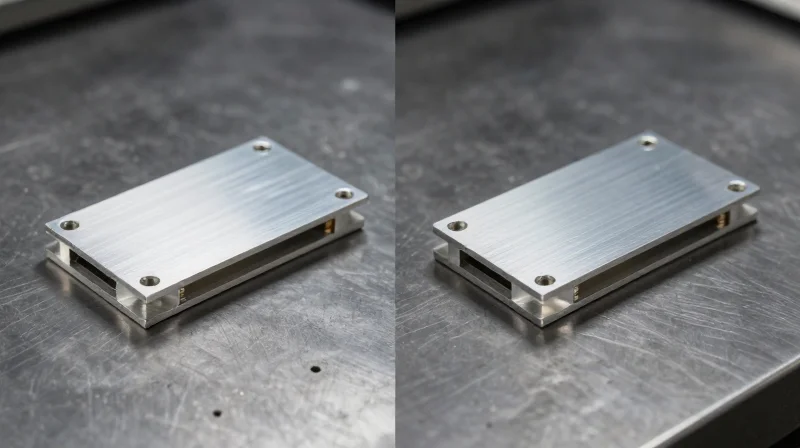
Critical Oversight: Thermal Expansion and Material Matching
One of the most frequent errors in procurement is the failure to account for the Coefficient of Thermal Expansion (CTE) mismatch between the LED components, the dielectric layer, and the aluminum base. In industrial LED drivers, where high power densities generate significant cyclic thermal loading, an improperly selected dielectric can lead to interfacial delamination or solder joint fractures. Procurement teams often prioritize cost over material grade, leading to the selection of low-cost thermal interfaces that fail to maintain integrity during extreme temperature swings.
Common Procurement Pitfalls
- Ignoring Dielectric Thermal Conductivity
Assuming all 'thermal' prepregs are identical. Different resins offer varying W/m·K values; selecting the wrong one can bottle-neck heat dissipation regardless of the aluminum base's performance. - Overlooking Surface Flatness Requirements
Failing to specify flatness tolerances for the aluminum base can result in poor thermal interface material (TIM) contact, creating hot spots that degrade LED life. - Inadequate Voltage Breakdown Ratings
Purchasing based on thickness alone while neglecting the dielectric's withstand voltage rating, which is critical for safety certification and preventing arcing in high-wattage drivers.
Comparative Analysis of Sourcing Specifications
| Parameter | Typical Procurement Error | Recommended Practice |
|---|---|---|
| Dielectric Thickness | Buying the thinnest available for heat transfer | Match thickness to required dielectric breakdown voltage |
| Thermal Conductivity | Assuming standard FR-4 ratings apply | Verify manufacturer data for 1.0–3.0 W/m·K materials |
| Base Alloy | Specifying generic aluminum | Specify 5052 or 6061 for optimal rigidity and thermal expansion |
Mitigation Strategies
To mitigate these risks, procurement must move beyond simple bill-of-materials matching. Always require the manufacturer to provide a material datasheet specifically for the dielectric stack-up. Conduct stress testing during the prototyping phase to ensure that thermal cycling does not lead to physical degradation. Finally, maintain a strict verification process for base alloy composition, as lower-grade alloys may exhibit warping during the reflow process, compromising the physical mounting of the LED driver assembly.
Testing and Validation Protocols

Establishing Thermal Performance Baselines
Before full-scale production, engineers must validate the thermal interface between the LED module and the aluminum substrate. Thermal cycling tests are the industry standard for this verification, simulating the expansion and contraction cycles that occur as the driver switches on and off. Failure to monitor the junction temperature (Tj) during these cycles often leads to dielectric breakdown or solder fatigue.
Standardized Testing Methodologies
| Test Protocol | Key Metric | Industrial Purpose |
|---|---|---|
| Thermal Shock | Delta T / Time | Tests solder joint integrity and adhesive layer stress. |
| High-Pot Testing | Leakage Current | Ensures the dielectric layer maintains insulation at high heat. |
| Humidity Exposure | Corrosion Rate | Validates surface finish resilience in harsh operating environments. |
Frequently Asked Questions on MCPCB Validation
- How long should thermal cycling tests last?
For industrial-grade LED drivers, a minimum of 500 to 1,000 cycles between -40°C and +105°C is recommended to detect early-stage delamination. - Why is dielectric strength testing critical?
As aluminum PCBs age, the dielectric layer can degrade; high-pot testing verifies that the safety insulation remains within specified limits to prevent short-circuiting. - What is the most common point of failure in tests?
The transition zone between the thermal interface material and the aluminum base is the most common failure point due to differing Coefficients of Thermal Expansion (CTE).
Best Practices for Reliability Validation
Implement continuous data logging during environmental stress screening (ESS). By monitoring voltage drops and heat dissipation rates in real-time, manufacturers can predict component lifespan rather than simply testing to failure. Always ensure that validation occurs on the full assembly, including the thermal interface material and heat sink, rather than the PCB in isolation, to gain an accurate assessment of field performance.
Selecting the correct aluminum PCB is a strategic investment in the longevity and efficiency of your industrial lighting projects. By prioritizing thermal conductivity and material integrity, you significantly reduce maintenance costs and hardware failure rates. If you are ready to optimize your LED driver design, reach out to our engineering team today to discuss your project requirements or request a custom quote for your next high-performance build.
