
In the fast-paced world of communication module integration, the precision of your castellated PCB can be the difference between market success and costly field failures. Selecting a manufacturing partner capable of delivering consistent, high-integrity edge plating is not just a sourcing decision; it is a critical engineering requirement for structural and signal reliability.
The Engineering Challenge of Castellated Holes
The Engineering Challenge of Castellated Holes
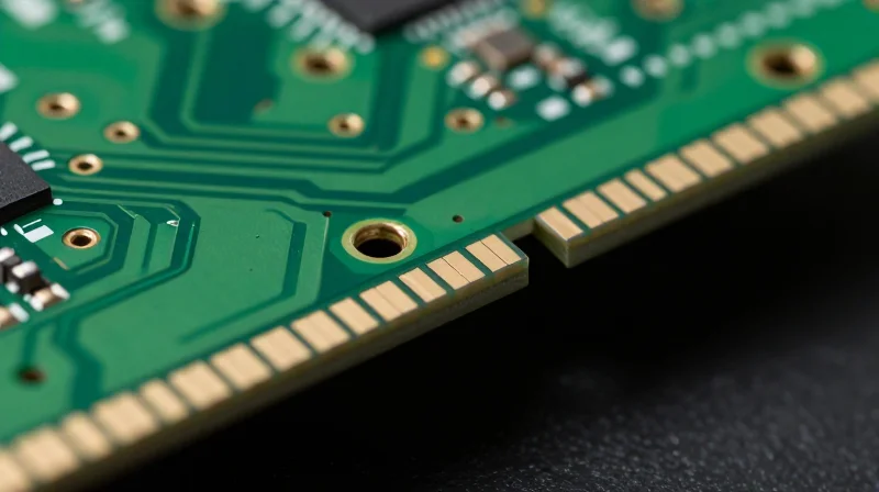
Castellated holes, or edge-plated castellations, serve as a critical interface for surface-mount modules. Unlike standard plated through-holes (PTH), these features are physically cut through the edge of the PCB, exposing the copper barrel to the environment. This mechanical transition introduces significant risks, including burr formation, plating delamination, and inconsistent solder joint reliability. Achieving high-yield results requires advanced fabrication processes to ensure the plated edges remain structurally sound and electrically conductive after the board is singulated.
Critical Fabrication Hurdles
- Burr Prevention
The routing process used to create the castellated edge often leaves copper burrs. Superior suppliers utilize controlled drilling and optimized routing sequences to minimize metal overhang. - Plating Adhesion
Copper barrels at the edge are prone to separation during the board separation process. Effective fabrication uses specialized chemistry to ensure robust bonding of the plating to the substrate material. - Surface Finish Consistency
Applying consistent surface finishes like ENIG or ENEPIG over exposed edge copper requires strict plating current density control to prevent uneven deposits.
| Feature | Standard PTH | Castellated Hole |
|---|---|---|
| Mechanical Stability | High (Encased) | Low (Exposed) |
| Singulation Risk | Negligible | High (Burrs/Delamination) |
| Process Complexity | Standard | High (Secondary Ops) |
For communication modules where impedance matching and thermal cycling are non-negotiable, selecting a supplier with proven experience in edge-plating is essential. Inadequate control over these parameters leads to poor solder wetting and potential signal integrity failures that can compromise the entire module's lifespan.
Evaluating Edge-Milling Precision
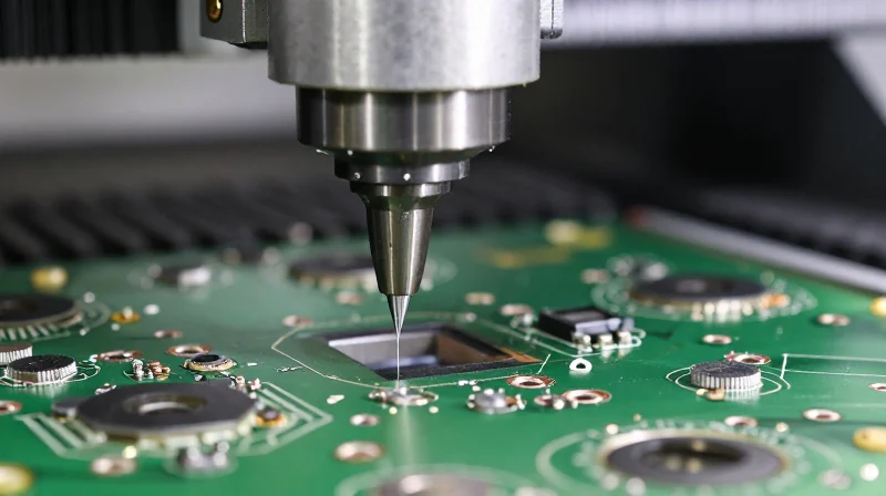
For communication modules, the transition from a standard PCB to a castellated daughterboard relies entirely on the quality of the cut across the plated through-holes. If the milling process is imprecise, it leads to burrs, copper tearing, or inconsistent side-plating geometries, which inevitably compromise solder joint reliability and impedes SMT assembly alignment.
Parameters of Precision Milling
| Parameter | Tolerance Standard | Impact on Integration |
|---|---|---|
| CNC Positioning | +/- 0.05mm | Ensures alignment with host board pads |
| Burr Removal | Zero tolerance | Prevents short circuits and assembly errors |
| Cut Depth Control | 0.1mm variation | Maintains plating thickness integrity |
Common Questions on Milling Accuracy
- Why do burrs occur during edge-milling?
Burrs occur when cutting tools are dull or when the feed rate is not synchronized with the copper plating thickness, causing mechanical tearing of the copper walls. - How does hole wall integrity affect high-frequency signals?
Imprecise milling can cause micro-cracks in the side plating, which increases impedance mismatch and causes signal degradation in high-speed communication modules. - What should I look for in a supplier's documentation?
Request their CNC tolerance data sheets and evidence of pre-milling plating reinforcement processes, which prevent copper separation during the final cut.
Selecting a supplier that utilizes automated optical inspection (AOI) specifically configured for edge-plating profiles is non-negotiable. Ensure your vendor validates every batch through cross-sectional analysis to verify that the plated wall remains perfectly intact after the milling cycle.
Assessing Plating Consistency and Adhesion
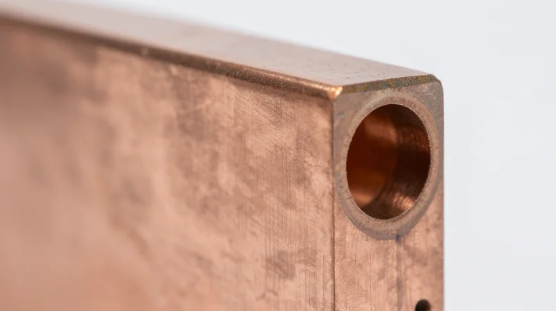
Achieving reliable electrical and mechanical connectivity in castellated PCBs hinges on the integrity of the metallic side-wall plating. When the plating process is suboptimal, the interface between the copper and the PCB substrate becomes a common point of failure, particularly under thermal cycling or vibration. A proficient supplier must demonstrate a closed-loop quality system that monitors electrolytic bath chemistry, current density, and the specific transition of the plating process after the castellated features have been mechanically milled.
Critical Metrics for Plating Quality
| Metric | Target Standard | Verification Method |
|---|---|---|
| Plating Thickness | 25-35 µm minimum | Cross-section Analysis |
| Adhesion Strength | No peeling after thermal shock | Tape Testing / IPC-TM-650 |
| Wall Roughness | Below 20 µm | Optical Profilometry |
Verifying Supplier Capability
To distinguish a high-tier supplier, you must look beyond basic certifications and request specific evidence of process control. Robust plating is not just about the chemistry; it is about how the supplier manages the 'edge' of the PCB to ensure that the copper deposit does not delaminate when the communication module is soldered to the mother board.
- How do you validate adhesion strength?
Suppliers should perform IPC-TM-650 compliant pull-tests and thermal stress tests to verify that the copper bond remains intact under high-temperature reflow conditions. - Does the supplier use micro-sectioning?
Reliable suppliers provide cross-sectional reports that document plating uniformity within the castellation and confirm the absence of voids or cracks at the substrate interface. - What post-plating treatment is provided?
Look for suppliers that apply secondary surface finishes like ENIG or Immersion Silver after milling, as these provide superior protection against oxidation compared to standard HASL.
Critical Quality Metrics and Inspection Standards
For communication modules, castellated holes act as critical interface points for surface-mount assembly. Quality control must transcend basic visual inspection, focusing on copper thickness, plating adhesion, and the precise mechanical removal of excess material to prevent short circuits and solder bridging.
Industry Standards and Compliance
Reliability in castellated PCBs is largely governed by adherence to IPC-A-600 and IPC-6012 standards. Suppliers must demonstrate proficiency in controlling the plating process within the half-holes to meet class 2 or class 3 requirements, depending on your module's end-use environment.
| Metric | Target Standard | Critical Checkpoint |
|---|---|---|
| Copper Thickness | IPC-6012 | Minimum 20-25µm inside the castellation |
| Burr Removal | Proprietary | Zero remaining debris or copper slivers |
| Surface Finish | IPC-A-600 | Uniform wetting without voids |
Key Quality Metrics for Inspection
- Plating Voids
Any voiding within the wall of the castellated hole represents a structural weakness that can lead to open circuits during thermal cycling. - Burr/Smear Presence
Edges must be micro-machined to remove conductive burrs left by the milling process; these are primary causes of latent shorts. - Soldering Reliability
The supplier should perform sample testing to verify that solder wicks correctly up the wall of the castellation without bridging to adjacent pads.
Verifying Supplier Inspection Protocols
When auditing a potential partner, request their internal Work Instructions (WI) for castellated features. A high-quality supplier will utilize Automated Optical Inspection (AOI) specifically programmed for edge features, rather than relying solely on manual microscope checks, to guarantee repeatability across high-volume production batches.
Signal Integrity Implications in High-Frequency Designs

Signal Integrity Implications in High-Frequency Designs
In high-frequency communication modules, the castellation serves as a critical transition point between the module board and the main PCB. Imperfections in the manufacturing of these holes—such as copper burrs, rough sidewalls, or inconsistent plating thickness—create abrupt impedance discontinuities. These discontinuities lead to signal reflections, increased insertion loss, and potential electromagnetic interference (EMI) that can compromise the overall link budget of your design.
Manufacturing Factors Affecting Signal Performance
| Defect Type | Impact on Signal | Resulting Issue |
|---|---|---|
| Copper Burrs | Uncontrolled stray capacitance | Increased Return Loss (S11) |
| Rough Sidewalls | Skin effect resistance increase | High Insertion Loss (S21) |
| Uneven Plating | Impedance mismatch | Signal distortion/Eye closure |
Common Technical Concerns
- How do edge plating defects cause EMI?
Irregular edges act as unintentional antennas. When high-frequency signals encounter discontinuities in the castellation geometry, current loops can become distorted, causing electromagnetic leakage and radiating noise that may violate FCC or CE compliance. - Does plating thickness affect frequency performance?
Yes, standard plating variations can alter the characteristic impedance of the castellated pad. At microwave frequencies, a deviation of even a few microns can shift the impedance, leading to poor matching with the host PCB pads. - Why is surface roughness critical for high-speed signals?
At higher frequencies, current flows primarily on the surface of the copper (skin effect). Any surface roughness or pitting inside the castellated hole increases the effective path length and electrical resistance, directly inflating insertion loss.
To mitigate these risks, ensure your supplier demonstrates advanced laser-drilling or controlled-depth CNC milling capabilities. Furthermore, request a Time Domain Reflectometry (TDR) test report specifically targeting the castellated interface to verify that the impedance remains within your design's tolerance window.
Importance of Supplier Certifications
Why Certifications Matter for Castellated PCBs
Castellated holes involve complex secondary drilling and edge plating processes that increase the risk of structural failure if not managed strictly. Certifications act as an objective audit of a factory's quality management system (QMS), ensuring that processes—from incoming material inspection to final edge-plating verification—are documented, repeatable, and capable of meeting strict communication module tolerances.
Core Quality Frameworks
| Certification | Primary Focus | Relevance to Castellated PCBs |
|---|---|---|
| ISO 9001 | General Quality Management | Ensures consistent processes are documented for every production batch. |
| IATF 16949 | Automotive Quality Standard | Requires advanced defect prevention and reduction in variation; ideal for mission-critical hardware. |
| AS9100 | Aerospace Quality | Offers the highest level of traceability and risk management for high-reliability components. |
Frequently Asked Questions Regarding Supplier Validation
- Does ISO 9001 certification alone guarantee high-quality castellations?
No, ISO 9001 provides a framework for quality, but it does not specify technical requirements for edge plating or secondary drilling. You must supplement this with technical specifications referencing IPC-A-600 Class 2 or 3 standards. - Why should I prioritize suppliers with IATF 16949 for communication modules?
IATF 16949 mandates rigorous statistical process control (SPC). For castellated holes, this means the supplier is tracking plating thickness and drill registration tolerances statistically to minimize the risk of intermittent connection failures. - How can I verify a supplier's certification claims?
Always request the current certificate document from the registrar. Verify the scope of the certification to ensure it covers the specific facility where the fabrication is performed, rather than just the corporate headquarters.
Due Diligence: Auditing Your Potential PCB Partner
Engineering-Led Audits: Moving Beyond Paper Certifications
While ISO and IATF certifications are essential, they do not guarantee proficiency in the niche art of castellated hole production. To verify a supplier's true capability, you must conduct an engineering-led audit that focuses on their manufacturing floor processes, specifically regarding edge-plating and mechanical routing precision.
Verification Checklist for Suppliers
- How do they handle the routing of half-holes?
Ensure they use secondary drilling or specialized CNC routing steps that prevent burrs or copper delamination at the edge interface, which are primary failure points in high-frequency modules. - What is their process for electroless copper deposition on edge surfaces?
Verify that their plating bath chemistry and cycle times are optimized for uniform edge coverage to avoid impedance discontinuities. - Do they provide cross-sectional micro-analysis reports?
A high-quality supplier will proactively offer micro-sections showing the bond between the hole wall plating and the surface pad.
Comparative Capability Matrix
| Audit Criteria | Low-Capability Supplier | Elite PCB Partner |
|---|---|---|
| Routing Precision | Standard tolerance, high burr rate | Laser-assisted or controlled-depth CNC |
| Edge Plating Consistency | Manual or inconsistent bath exposure | Automated vertical plating control |
| QA Transparency | Visual inspection only | X-ray + micro-section reporting |
The Importance of Pilot Runs
Never commit to high-volume production without a rigorous 'Pre-Production Verification' (PPV) run. During this phase, you should specifically test the castellated surfaces for solderability and potential impedance variations. If a supplier refuses to provide detailed manufacturing process flowcharts for these test boards, it is an indicator that their process may lack the necessary maturity for your specific integration needs.
Avoiding Common Pitfalls in Castellated Fabrication
The fabrication of castellated holes, often referred to as semi-plated holes, introduces unique mechanical and electrical challenges. Even minor deviations in the manufacturing process can lead to significant assembly failures, such as poor solder joint reliability or electrical shorts, which are especially critical for sensitive communication modules.
Critical Fabrication Red Flags
- Burrs and Metallic Residue
Inadequate drilling techniques or improper post-process routing often leave copper burrs. These remnants can lead to electrical shorts between castellated pads or interfere with the physical mounting of the module. - Insufficient Plating Thickness
Castellations require robust plating within the half-holes to ensure a reliable solder connection. If the plating is too thin, you risk thermal stress failure during reflow soldering. - Non-Standard Pad Geometries
Suppliers must have specific design rule clearances for castellated pads. Relying on default settings without consulting your vendor frequently results in breakout issues where the drill hits the pad edge prematurely.
Comparison of Prototyping vs. Production Risks
| Risk Factor | Prototype Phase Impact | Production Phase Impact |
|---|---|---|
| Drill Registration | Manual rework feasible | High scrap rate/Field failure |
| Copper Burrs | Easily identified visually | Intermittent shorts/EMI issues |
| Solder Mask Encroachment | Difficulty in mounting | Poor reliability/Mechanical stress |
Mitigation Strategies for Reliable Integration
To mitigate these pitfalls, engage your supplier early. Ensure that your Gerber files explicitly label the castellated edges and that your stack-up is compatible with the supplier's secondary drilling process. Implementing a strict 'First Article Inspection' (FAI) report that specifically details castellated hole geometry is essential before moving to mass production.
Selecting a partner for complex castellated module production requires prioritizing technical capability and consistent quality control over simple price comparisons. By focusing on these specific manufacturing benchmarks, you safeguard your hardware’s performance. Ready to discuss your next high-reliability project? Contact our engineering team today to see how we can support your specific design requirements.
