
In the world of mission-critical electronics, a Printed Circuit Board (PCB) is only as reliable as the environment it can withstand. From corrosive industrial gases to extreme thermal cycling, your components face constant threats. Selecting the correct conformal coating isn't just about covering the board—it's about engineering long-term performance.
The Strategic Importance of PCB Conformal Coating
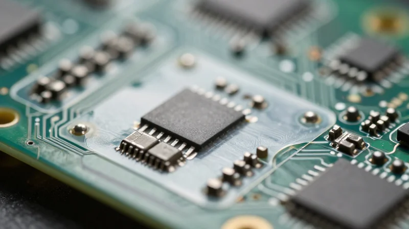
The Strategic Role of Conformal Coating
In industrial environments, a Printed Circuit Board (PCB) is rarely an isolated component; it is the central nervous system of complex machinery. Conformal coating acts as a protective polymeric film that conforms to the board's contours, insulating sensitive components from atmospheric threats. By establishing a robust barrier, manufacturers significantly extend the Mean Time Between Failures (MTBF) and reduce the need for costly field repairs or system downtime.
Key Environmental Defense Mechanisms
- Moisture Mitigation
Prevents the formation of conductive bridges and electrolytic corrosion by blocking water vapor and humidity from reaching the PCB surface. - Chemical and Corrosive Protection
Acts as a chemical-resistant layer against salt spray, acidic vapors, and industrial solvents that would otherwise degrade solder joints and copper traces. - Thermal and Mechanical Stress Relief
Helps manage the impact of rapid temperature fluctuations, reducing the risk of component detachment or micro-cracking during thermal expansion and contraction.
Impact of Failing to Protect PCBs
| Risk Factor | Result of Lack of Protection | Business Impact |
|---|---|---|
| Oxidation | Trace corrosion and high resistance | Signal loss and erratic system behavior |
| Dendritic Growth | Formation of conductive filaments | Short circuits and catastrophic failures |
| Contaminant Deposition | Dust and grime buildup | Overheating and reduced operational lifespan |
Selecting the right coating is not merely an afterthought; it is a fundamental design decision that directly correlates to the long-term reliability and profitability of industrial hardware.
Assessing Environmental Stress Factors
Identifying Environmental Stressors
Selecting the appropriate conformal coating requires a systematic audit of the operating environment. A coating that excels in high-vibration aerospace applications may fail prematurely in a chemically aggressive automotive under-hood environment. Understanding the synergy between these factors is essential for preventing premature hardware failure.
Primary Environmental Threats
| Environmental Factor | Primary Risk to PCB | Coating Solution Category |
|---|---|---|
| High Humidity | Dendrite growth and corrosion | Parylene or Silicone |
| Chemical Exposure | Degradation and swelling | Epoxy or Urethane |
| Thermal Cycling | Delamination and micro-cracking | Acrylic or Silicone |
| Mechanical Shock | Solder joint fatigue | Flexible Urethane |
Frequently Asked Questions
- How does high humidity specifically damage industrial PCBs?
Moisture creates a conductive path between fine-pitch components, leading to electrochemical migration, metal whiskering, and eventually catastrophic short circuits. - Why is thermal cycling a critical factor in coating selection?
Rapid temperature shifts cause differential expansion between the PCB substrate and the coating, which can lead to stress-induced delamination and surface cracking if the coating lacks proper elasticity. - Does chemical resistance always imply better protection?
Not necessarily. Highly chemical-resistant coatings, like certain epoxies, are often very rigid, which may compromise protection against physical vibrations compared to more flexible silicone-based options.
Chemical Resistance and Material Compatibility
Chemical Resistance and Material Compatibility
The efficacy of a conformal coating is ultimately defined by its ability to maintain barrier integrity when challenged by oils, solvents, acids, and airborne gases. Material compatibility is a bidirectional requirement: the coating must resist the chemical environment, while simultaneously remaining chemically inert toward the PCB components, solder masks, and flux residues to prevent long-term degradation or adhesion failure.
| Coating Type | Solvent Resistance | Chemical Compatibility Profile |
|---|---|---|
| Acrylics | Low | Excellent general-purpose; soluble in common solvents for easy rework. |
| Urethanes | High | Robust against oils and fuels; can be sensitive to aggressive chemical stripping agents. |
| Silicones | Moderate | Resists high heat and moisture; susceptible to solvent swelling if not properly cured. |
| Parylene | Very High | Chemically inert; provides superior protection against acids and moisture with zero outgassing. |
Assessing Compatibility Hazards
- How does solvent exposure impact coating selection?
If the PCB will be exposed to hydrocarbon-based cleaners or fuels, acrylics should be avoided as they will dissolve, whereas urethanes or parylene offer far superior chemical stability. - Can residual flux affect coating adhesion?
Yes; chemical incompatibility between flux residues and the coating can lead to delamination. Always ensure the PCB cleaning process is compatible with the selected chemistry to prevent 'fish-eye' defects. - Does the coating impact sensitive electronic components?
Some coatings contain volatile organic compounds (VOCs) that can corrode sensitive relays or sensors; low-outgassing materials like silicones or parylene are preferred for high-precision instrumentation.
Engineers must also conduct thermal cycling tests in combination with chemical exposure. A coating that is chemically resistant at room temperature may lose its barrier properties when mechanical expansion/contraction occurs during thermal fluctuations, potentially creating microscopic cracks that allow chemical ingress.
Thermal Stability and Operating Temperature Ranges
Thermal Performance and Mechanical Integrity
When assessing thermal requirements for industrial PCB protection, the primary goal is to ensure the coating maintains its physical properties across the device's entire operating range. A coating that is stable at ambient temperatures may become brittle and crack during cold-start cycles or soften and lose dielectric strength under continuous high-heat operations. Engineers must prioritize the glass transition temperature (Tg) of the polymer; if a coating operates near or above its Tg, its coefficient of thermal expansion (CTE) increases significantly, which can induce stress on delicate solder joints and component leads during thermal cycling.
| Coating Type | Typical Operating Range (°C) | Thermal Performance Notes |
|---|---|---|
| Acrylic | -40°C to 125°C | Moderate performance; risk of softening at high heat. |
| Polyurethane | -40°C to 125°C | Good thermal stability but prone to stress at low temperatures. |
| Silicone | -65°C to 200°C | Excellent flexibility; maintains integrity during extreme thermal shock. |
| Parylene | -200°C to 150°C | Superior stability; withstands wide thermal ranges without outgassing. |
Thermal Management FAQs
- How does thermal expansion mismatch affect conformal coating selection?
If the CTE of the coating significantly exceeds that of the PCB substrate and components, thermal cycling will cause the coating to contract and expand at different rates, leading to delamination or mechanical fatigue in solder joints. - Why is the glass transition temperature (Tg) significant?
The Tg indicates the point where the polymer changes from a rigid, glassy state to a rubbery state. Operating consistently above the Tg can lead to increased gas permeability and potential loss of adhesion. - Does high heat affect the dielectric properties of a coating?
Yes. Elevated temperatures can lead to dielectric constant shifts and potential degradation of insulation resistance, potentially causing electrical leakage or short circuits in high-voltage applications.
Navigating Industry Standards: IPC-CC-830 and Beyond
In the high-stakes world of industrial electronics, performance claims without validation are insufficient. Industry standards act as the baseline for reliability, ensuring that the selected conformal coating will perform consistently under the rigorous demands of harsh environments. Relying on materials tested against established benchmarks mitigates the risk of field failures, expensive warranty claims, and system downtime.
Understanding IPC-CC-830 and UL Benchmarks
The primary industry standard for printed board assemblies is IPC-CC-830, which defines the qualification and performance requirements for electrical insulating compounds. Coatings that pass this certification are tested for thermal shock, humidity resistance, and fungus resistance. Complementing this, UL (Underwriters Laboratories) standards—specifically UL 94 for flammability and UL 746E for industrial coatings—provide critical safety and dielectric ratings, ensuring the material will not contribute to fire spread or electrical failure under stress.
| Standard | Primary Focus | Industry Relevance |
|---|---|---|
| IPC-CC-830 | Performance & Qualification | Ensures basic reliability and chemical resistance. |
| UL 746E | Dielectric/Flame Safety | Essential for high-voltage and safety-critical apps. |
| MIL-I-46058C | Military Specification | Legacy standard often referenced for extreme durability. |
Navigating Standards in Specification
- Why is IPC-CC-830 considered the baseline?
It provides a standardized test protocol that allows engineers to compare different coating chemistries (Acrylic vs. Silicone) using a uniform set of stress parameters, ensuring apples-to-apples performance evaluation. - When is UL certification mandatory?
UL certification is generally required for products sold in North American industrial markets, especially if the device manages high power, poses a fire risk, or is intended for use in explosion-proof environments. - Does passing a standard guarantee performance?
No; while these standards ensure the material meets basic industrial benchmarks, they do not replace application-specific testing (such as actual salt-spray or vibration testing) tailored to your unique end-use conditions.
Ultimately, while IPC and UL standards provide the necessary trust framework, designers must go beyond certification by verifying material data sheets against their specific environmental stressors. Always require the manufacturer's Certificate of Conformance (CoC) for each batch to ensure the chemistry remains consistent with the certified formulation.
Application Methods and Manufacturing Scalability
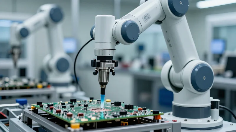
The efficacy of a conformal coating depends not only on its chemical properties but also on how consistently it is applied to the PCB assembly. Choosing between manual application and automated robotic systems involves evaluating volume requirements, the complexity of the board geometry, and the desired level of process repeatability.
Comparative Analysis of Application Methodologies
| Method | Volume Suitability | Cost Efficiency | Process Control |
|---|---|---|---|
| Brushing | Low (Prototyping) | High | Low |
| Spraying | Medium | Moderate | Medium |
| Robotic Dispensing | High (Mass Production) | High (Long-term) | Very High |
Evaluating Scalability and Precision
For low-volume or prototyping environments, manual brushing is often sufficient, though it lacks the consistency required for high-reliability standards. As production scales, aerosol or air-atomized spraying offers a middle ground, providing better film uniformity. However, for industrial-grade protection—where masking precision and thickness control are paramount—robotic selective coating systems are the gold standard. These systems minimize waste, ensure repeatability across thousands of units, and integrate seamlessly into high-speed SMT lines.
Frequently Asked Questions
- Why is robotic dispensing preferred for high-reliability applications?
Robotic systems ensure precise film thickness and can navigate complex board topographies without coating restricted areas, drastically reducing the risk of process-induced defects. - Does the application method affect the curing process?
Yes, manual application often leads to thicker, uneven layers that can cause bubble entrapment or uneven curing, potentially leading to long-term cracking or delamination. - How do I determine if my manufacturing volume justifies automation?
Consider the labor cost versus material waste ratio; if manual rework rates exceed 5%, the investment in a selective robotic coating cell usually yields a positive ROI within the first year of production.
Testing Protocols for Long-Term Reliability
Validating Long-Term Reliability via Accelerated Life Testing
To ensure an industrial PCB can survive decades of operation, engineers must move beyond basic data sheet specifications. Accelerated Life Testing (ALT) utilizes controlled stress factors—specifically thermal cycling and high-humidity exposure—to simulate years of field degradation in a matter of weeks. The objective is to identify potential failure modes such as micro-cracking, delamination, or insulation resistance drops before the product reaches the deployment stage.
Comparison of Standard Environmental Stress Tests
| Test Protocol | Primary Stressor | Failure Mode Detected |
|---|---|---|
| Thermal Shock | Rapid Temperature Fluctuation | Cracking, Delamination |
| Salt Fog (ASTM B117) | Corrosive Chloride Mist | Electrochemical Migration, Corrosion |
| THB Testing | 85/85 Humidity & Bias | Dendrite Growth, Leakage Current |
Implementing Salt Fog and Humidity Protocols
Salt Fog testing, conducted under ASTM B117 standards, is essential for PCBs deployed in coastal or heavy industrial chemical environments. When applying these protocols, focus on the integrity of the coating interface at high-density interconnects where salt ions are most likely to bridge gaps. Following exposure, performing a Surface Insulation Resistance (SIR) measurement is the gold standard for quantifying whether the coating has truly maintained its dielectric barrier integrity.
Frequently Asked Questions on Reliability Testing
- How many thermal cycles are recommended for industrial validation?
A minimum of 500 to 1,000 cycles between extreme operating temperatures is generally recommended for high-reliability industrial hardware. - Does passing IPC-CC-830 guarantee environmental survival?
No, IPC-CC-830 validates qualification, not performance. Application-specific ALT remains necessary to ensure the coating handles the unique mechanical and chemical stresses of your specific environment. - What is the most common cause of coating failure in testing?
Improper surface preparation, such as residual flux or contaminants under the coating, is the leading cause of premature delamination during environmental stress testing.
Avoiding Common Pitfalls in Coating Selection
Strategic Mitigation of Coating Failures
The most frequent failures in PCB protection—delamination, cracking, and dielectric breakdown—often stem from overlooked process variables rather than material quality. Achieving a high-reliability finish requires a disciplined approach to surface energy, contamination control, and curing parameters.
| Common Pitfall | Root Cause | Prevention Strategy |
|---|---|---|
| Poor Adhesion | Surface contamination or low surface energy | Implement plasma treatment or rigorous aqueous cleaning cycles. |
| Micro-bubbles | Incorrect viscosity or high-pressure spray | Optimize thinner ratios and maintain consistent ambient humidity. |
| Masking Failure | Excessive bleed-under or improper tape selection | Utilize die-cut masking shapes and ensure firm, edge-sealed application. |
Addressing Surface Compatibility Issues
A common mistake is assuming uniform adhesion across all board components. Solder masks, in particular, can vary significantly in chemistry. Before full-scale production, verify the surface energy of your substrate to ensure it is compatible with the surface tension of the selected coating; failing this, the coating may 'bead' rather than wet, leading to protected regions that are actually susceptible to moisture ingress.
Frequently Asked Questions on Coating Integrity
- How can I prevent air bubbles in high-viscosity coatings?
Avoid excessive manual mixing and ensure that the dispensing system maintains a steady flow rate without rapid directional changes. If using automated spray, verify that the fluid pressure and atomizing air are balanced to minimize entrapped air. - Why does my coating peel off specifically near solder joints?
This is often due to 'thermal mismatch' or residual flux. Ensure all ionic residues are removed via validated cleaning processes, as leftover flux acts as a bond breaker during thermal cycling. - Is tape masking reliable for high-volume production?
Manual masking is prone to human error and inconsistency. For high-volume environments, consider liquid peelable masks or mechanical fixtures that provide consistent edge definition and prevent capillary action from drawing coating into protected areas.
Selecting the right conformal coating is a foundational step in ensuring the longevity of your industrial electronics. By balancing material properties with environmental realities and strict adherence to IPC standards, you mitigate risk and maximize field performance. Contact our engineering team today to review your project requirements and find the ideal protective solution for your critical assets.
