
In the high-stakes world of industrial automation, an HMI (Human-Machine Interface) is only as reliable as the printed circuit board beneath its surface. When exposed to extreme temperatures, constant vibration, and intense electromagnetic interference, standard consumer-grade boards fail—costing businesses thousands in downtime. This guide breaks down the mission-critical criteria for selecting industrial-grade PCBs that ensure your automation systems stay operational under the most punishing conditions.
The Anatomy of a Failure: Why Industrial Environments Demand Specialized PCBs
Environmental Stressors and Component Degradation
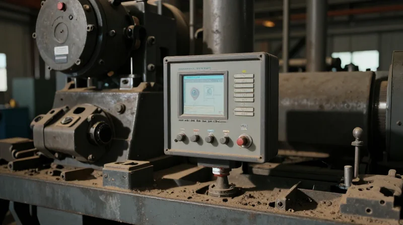
Industrial environments are fundamentally different from office or consumer spaces. The reliability of an HMI (Human-Machine Interface) relies heavily on the PCB's ability to withstand thermal cycling, high humidity, mechanical vibration, and corrosive airborne contaminants. A standard consumer-grade board will likely experience solder joint fracturing, layer delamination, or conductive path corrosion within weeks of deployment in a harsh factory setting.
| Stressor | Primary Failure Mode | Industrial Mitigation |
|---|---|---|
| Thermal Cycling | Solder fatigue/cracking | High-Tg substrate materials |
| Humidity/Condensation | Electrochemical migration | Conformal coating/Potting |
| Mechanical Vibration | Interconnect failure | Enhanced component securing/anchoring |
| Corrosive Gases | Trace oxidation/shorting | Immersion gold or selective plating |
Key Questions for Industrial PCB Reliability
- Why does standard board thickness matter?
Standard boards (1.6mm) may lack the rigidity to resist bowing under the intense vibrations common in heavy industrial machinery, leading to micro-cracks in traces. - What role does Tg (Glass Transition Temperature) play?
High-Tg materials ensure the board maintains mechanical stability at elevated temperatures, preventing delamination during continuous 24/7 operation. - How does conformal coating protect against moisture?
It acts as a protective dielectric film that prevents condensation from forming conductive bridges between closely spaced SMD components, effectively stopping short-circuiting.
Thermal Management: Designing for Extreme Operating Temperatures
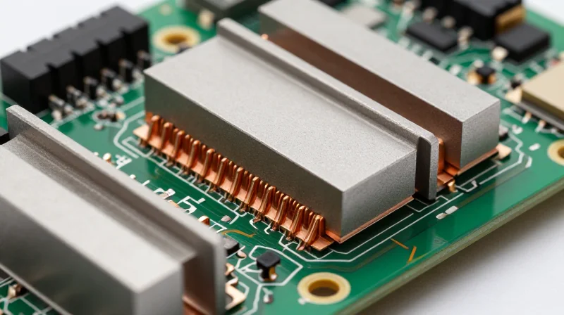
Industrial HMI units are frequently housed in sealed, fanless enclosures to protect against dust and liquid ingress. While this improves ingress protection, it creates a significant thermal challenge, as heat generated by the processor, display, and power management circuits becomes trapped. Failure to effectively manage this heat leads to dielectric breakdown, solder joint fatigue, and premature failure of sensitive surface-mount components.
Selecting the Right Substrate: The Role of Glass Transition Temperature (Tg)
The glass transition temperature (Tg) is the threshold at which a PCB substrate transitions from a rigid, glass-like state to a softer, rubbery state. For industrial automation systems operating in high-temperature environments, selecting a high-Tg material (typically 170°C or higher) is critical. Exceeding the Tg causes the laminate to expand at a higher rate, which puts mechanical stress on plated through-holes and copper traces, often resulting in intermittent electrical connectivity.
| Material Type | Typical Tg (°C) | Recommended Industrial Use |
|---|---|---|
| Standard FR-4 | 130-140 | Not suitable for sealed industrial HMI |
| Mid-Tg FR-4 | 150-160 | Moderate duty automation systems |
| High-Tg Epoxy/Polyimide | 170-250 | Critical HMI/Touch control panels |
Thermal Path Engineering in Sealed Enclosures
Beyond material selection, designers must implement a robust thermal conductive path from the PCB components to the exterior enclosure. In fanless HMI systems, this is typically achieved using thermal interface materials (TIMs) that bridge the gap between high-power chips and the chassis, turning the enclosure itself into a large heat sink.
- Why is standard FR-4 often insufficient for industrial HMIs?
Standard FR-4 has a lower Tg and inferior coefficient of thermal expansion (CTE) stability, making it prone to delamination and trace fracturing under the cyclic heating and cooling seen in continuous-duty industrial applications. - How do thermal vias assist in heat dissipation?
Thermal vias are small, copper-plated holes that move heat from the top layer of the PCB to internal copper planes or the bottom side, effectively spreading the heat across a larger surface area to prevent localized hotspots. - What role do copper weights play in heat management?
Heavier copper weights (e.g., 2oz or higher) not only support higher current flow but also act as a heat spreader, effectively conducting thermal energy away from high-density power components.
Advanced PCB Materials and Substrate Selection
In industrial HMI and touch panel automation, the PCB substrate acts as both the electrical foundation and the primary thermal interface. As systems become more compact and processing demands increase, the selection between traditional FR-4, Metal-Core PCBs (MCPCB), and advanced ceramics must be guided by the specific thermal load and physical stress profiles of the application.
Substrate Material Comparison
| Material | Thermal Conductivity | Dielectric Strength | Best Application |
|---|---|---|---|
| FR-4 (High-Tg) | Low (0.25 W/mK) | Excellent | General logic & IO boards |
| MCPCB (Aluminum) | High (1.0 - 3.0 W/mK) | Moderate | High-brightness LED backlights |
| Ceramic (Alumina/AlN) | Very High (20 - 180 W/mK) | Superior | Extreme power density modules |
Material Performance Characteristics
While standard FR-4 remains the industry baseline for its cost-effectiveness, it often fails under the localized heat spots common in modern HMI touch controllers. MCPCBs utilize a thin dielectric layer over an aluminum or copper base to facilitate rapid heat transfer away from high-power integrated circuits, effectively extending the lifespan of backlight drivers and processing units. For applications requiring extreme dielectric stability or high-frequency signal integrity under thermal cycling, ceramic substrates such as Alumina or Aluminum Nitride offer near-perfect thermal expansion matching to silicon dies.
Substrate Selection FAQ
- When is FR-4 insufficient for HMI design?
FR-4 becomes a bottleneck when localized power densities exceed the board's ability to dissipate heat, leading to glass transition (Tg) degradation and potential delamination. - Why choose Aluminum-Core over Copper-Core PCBs?
Aluminum-Core PCBs offer a lighter, lower-cost thermal management solution suitable for most HMI panels, whereas Copper-Core is reserved for extreme power densities requiring maximum thermal conductivity. - How do dielectric properties affect touch screen accuracy?
High-frequency noise from poorly chosen substrates can interfere with capacitive touch sensors; stable dielectric constants in materials like polyimide or specialized ceramics are preferred for sensitive touch overlays.
Combating EMI and Signal Integrity in Noise-Heavy Zones
Minimizing Signal Degradation through Strategic Stack-up Design
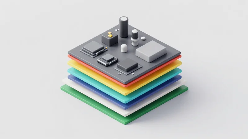
The foundation of signal integrity in industrial HMIs lies in a disciplined PCB layer stack-up. By utilizing a multi-layer approach, engineers can isolate sensitive analog touch-sensor traces from high-speed digital switching noise. The primary strategy involves placing ground planes adjacent to signal layers to provide a low-impedance return path, which minimizes loop areas and reduces unintended electromagnetic radiation.
Techniques for Advanced EMI Suppression
- Why is layer stack-up critical for HMI touch panels?
Industrial HMI touch panels are susceptible to capacitive noise; a proper 4- or 6-layer stack-up ensures that ground planes sandwich sensitive traces, preventing crosstalk and external interference from impacting touch sensitivity. - How does Faraday cage integration enhance PCB protection?
For highly sensitive signal processing circuits, implementing a board-level shield or a 'Faraday cage' via a dedicated metal enclosure connected to the PCB chassis ground effectively blocks high-frequency electromagnetic waves from reaching sensitive components. - What role do guard traces play in signal integrity?
Guard traces are grounded conductors placed alongside sensitive signal paths. They intercept fringe electrical fields, providing an extra layer of defense against coupling noise in dense board layouts.
Comparison of EMI Mitigation Strategies
| Mitigation Method | Effectiveness | Primary Application |
|---|---|---|
| Ground Plane Isolation | High | Digital-Analog noise separation |
| Board-Level Shielding | Very High | RF-sensitive components |
| Differential Signaling | Medium | High-speed data bus integrity |
Beyond stack-up, PCB layout designers must enforce strict design rules regarding trace routing. Using differential pairs for high-speed signals minimizes the emission of common-mode noise, while strictly avoiding crossing traces over gaps in the ground plane—a common oversight that creates impedance discontinuities and EMI 'hot spots' that disrupt industrial performance.
Durability Through Protective Coatings and Conformal Coating
The Role of Conformal Coatings in Industrial Resilience
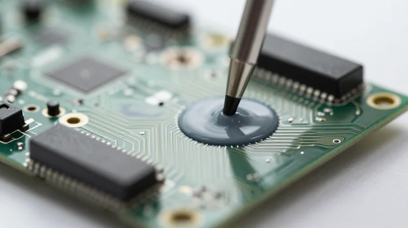
Conformal coatings serve as the primary defensive layer for PCBs, shielding sensitive circuitry from environmental degradation such as moisture, dust, chemical vapors, and conductive particulates. In HMI systems, where ingress is often unavoidable due to ventilation or seal degradation, these coatings prevent dendritic growth and short circuits, maintaining long-term electrical reliability.
| Coating Type | Primary Benefit | Best Used For |
|---|---|---|
| Acrylic (AR) | Easy application/rework | General protection |
| Silicone (SR) | High thermal stability | High-temperature HMIs |
| Urethane (UR) | Chemical resistance | Solvent-rich environments |
| Parylene | Superior pinhole-free seal | Extreme harsh conditions |
Potting Compounds for Mechanical and Environmental Hardening
For industrial touch panels subjected to extreme vibration or high-pressure washdown cycles, conformal coating may be insufficient. Potting compounds, which encapsulate the entire PCB assembly in a resin (epoxy, polyurethane, or silicone), provide structural reinforcement, vibration dampening, and an impenetrable moisture barrier.
Frequently Asked Questions
- Can conformal coatings cause overheating?
Most thin-film coatings have negligible thermal resistance. However, thick potting compounds can act as insulators; ensure heat-generating components are either left unpotted or paired with effective thermal management materials. - How does chemical exposure affect coating choice?
Standard acrylics may dissolve or soften under aggressive solvents. In chemical processing plants, specialized urethane or epoxy coatings are required to ensure the protective barrier remains intact. - Is reworkability a significant factor for HMIs?
If the HMI is mission-critical and expensive to replace, selecting a reworkable coating like Acrylic or Silicone is preferred over permanent, non-reworkable potting compounds.
Vibration Resistance: Solder Joints and Mechanical Mounting
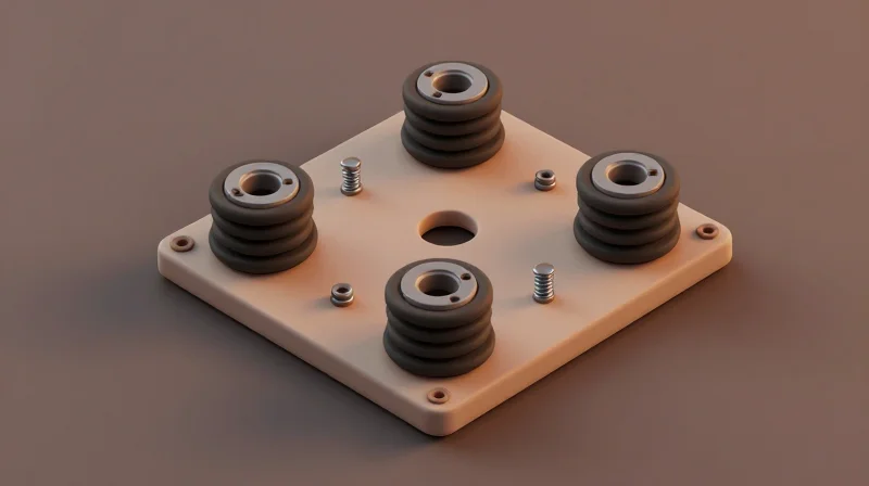
In industrial HMI environments, constant mechanical oscillation—often caused by nearby heavy machinery, motors, or automated transport systems—imposes significant stress on PCB solder joints. Failure to account for these dynamic loads can lead to micro-fractures, intermittent connectivity, and catastrophic system downtime. Engineers must prioritize high-ductility solder alloys, strategic component placement, and robust mechanical mounting to mitigate these fatigue-related risks.
Advanced Solder Alloy Selection
Standard SAC305 (Sn-Ag-Cu) alloys, while RoHS compliant, are often too brittle for high-vibration environments. For extreme industrial applications, moving to doped solder alloys can significantly increase lifespan.
| Solder Alloy | Vibration Resistance | Recommended Application |
|---|---|---|
| SAC305 | Moderate | General-purpose office/controlled HMI |
| Innolot | High | Heavy-duty automation and automotive |
| Sn-Cu-Ni (with dopants) | Very High | Extreme thermal cycling and vibration |
Mechanical Mounting and Stress Mitigation
The PCB should never be the sole structural support for an HMI display. Effective mechanical design utilizes vibration-dampening standoffs and perimeter support to isolate the board from chassis resonances.
- How do board dimensions impact vibration survival?
Larger PCBs are prone to high-amplitude resonance at lower frequencies; minimizing unsupported board span with well-placed mounting screws significantly raises the natural frequency of the assembly. - Does component orientation matter?
Yes, orienting heavy components such as inductors or electrolytic capacitors so their longest axis is parallel to the primary vibration vector reduces the leverage exerted on solder pads. - Why use edge-supported mounting?
Full perimeter support via guide rails or mounting frames prevents PCB bowing, which is a leading cause of stress-induced solder cracking in touch panels.
Strategic Component Placement
Designers should prioritize placing high-mass components near mounting points to reduce displacement. Furthermore, BGA components should be placed in areas of minimum PCB deflection, and underfilling these chips with epoxy is recommended if the unit is subject to constant motion, as it transfers mechanical load from the solder bumps to the package body.
Compliance and Standards: IPC-6012 and Beyond
The Role of IPC-6012 in Industrial Reliability
IPC-6012 serves as the benchmark for rigid printed board qualification and performance. For industrial HMIs, which often operate in environments defined by extreme thermal cycling, humidity, and mechanical stress, specifying IPC-6012 Class 3 is essential. Class 3 mandates higher standards for hole wall copper thickness, plating voids, and dielectric spacing, providing the structural integrity required for mission-critical automation hardware that cannot afford downtime.
Comparing Performance Classes
| Class Level | Typical Application | Reliability Requirement |
|---|---|---|
| Class 1 | Consumer Electronics | General/Standard |
| Class 2 | Dedicated Service | High reliability expected |
| Class 3 | Industrial/Medical | Continuous performance, no downtime |
Beyond IPC-6012: Regulatory Compliance
Compliance extends beyond mechanical standards to environmental and safety certifications. Industrial HMI systems integrated into global supply chains must strictly adhere to RoHS (Restriction of Hazardous Substances) and REACH directives. Furthermore, for systems operating in hazardous zones, compliance with ATEX or IECEx standards ensures that the PCB design does not introduce ignition risks in explosive atmospheres.
Frequently Asked Questions Regarding Compliance
- Is IPC-6012 Class 3 required for all industrial HMI?
While not legally mandated in all regions, it is the industry standard for systems where failure results in significant financial loss or safety hazards, such as factory floor automation. - How does PCB cleanliness (IPC-J-STD-001) impact reliability?
Residual ionic contamination can lead to dendrite growth and leakage currents, which are common failure modes in high-humidity industrial environments; adhering to ionic cleanliness standards is vital. - What documentation should I demand from my PCB fabricator?
Always request a Certificate of Conformance (CoC), microsection reports, and thermal stress test results to verify that the manufactured board meets the specified IPC class requirements.
Lifecycle Management and Obsolescence Planning
The Challenge of Component Obsolescence in Industrial Automation
Industrial HMI systems often outlive the individual electronic components on their PCBs. When processors, display controllers, or power management ICs reach end-of-life (EOL), the manufacturer faces costly redesigns or unplanned supply chain outages. Proactive lifecycle management ensures that the bill of materials (BOM) is designed for longevity, prioritizing components with multi-year availability guarantees from tier-one manufacturers.
Strategies for Long-Term PCB Stability
- Select Long-Life Silicon
Choose components from manufacturers that explicitly publish a 'Product Longevity Program,' which guarantees availability for 10 to 15 years. - Modular Architecture
Utilize System-on-Modules (SoMs) for the core compute functionality. This allows you to upgrade or swap the processor module without replacing the entire carrier PCB. - BOM Risk Auditing
Regularly monitor your component list against lifecycle databases to identify 'not-recommended-for-new-design' (NRND) parts before they reach total obsolescence.
Comparison: Short-Term vs. Long-Term Component Strategy
| Feature | Short-Term/Consumer Focus | Long-Term/Industrial Focus |
|---|---|---|
| Typical Availability | 1–3 years | 10–15 years |
| Supplier Support | Limited to high-volume orders | Direct enterprise support |
| Design Philosophy | Performance-per-watt optimization | Stability and supply continuity |
| Risk Impact | Frequent redesign cycles | High reliability and low TCO |
Key Considerations for Obsolescence Planning
Effective obsolescence planning is not a one-time task but a continuous cycle of monitoring and adaptation. By implementing a 'design-for-availability' mindset, engineering teams can minimize the impact of component phase-outs, ensuring that critical automation assets remain operational throughout their expected service life without the need for expensive, unplanned hardware refreshes.
Selecting the right PCB is the foundation of a successful, long-lasting industrial automation system. By prioritizing thermal performance, material resilience, and shielding against electrical noise, you can drastically reduce maintenance costs and system failure rates. Ready to build hardware that stands the test of time? Contact our engineering team today to review your project specifications and ensure your HMI platform is built for the factory floor of the future.
