
Industrial welding machines operate in some of the most unforgiving environments imaginable, subjecting critical electronics to massive electrical surges and intense thermal stress. Choosing the wrong PCB manufacturer can result in catastrophic field failures and costly downtime. This guide breaks down the essential technical requirements and vetting processes to ensure your high-power designs survive the factory floor.
The Unique Challenges of High-Power Welding Electronics
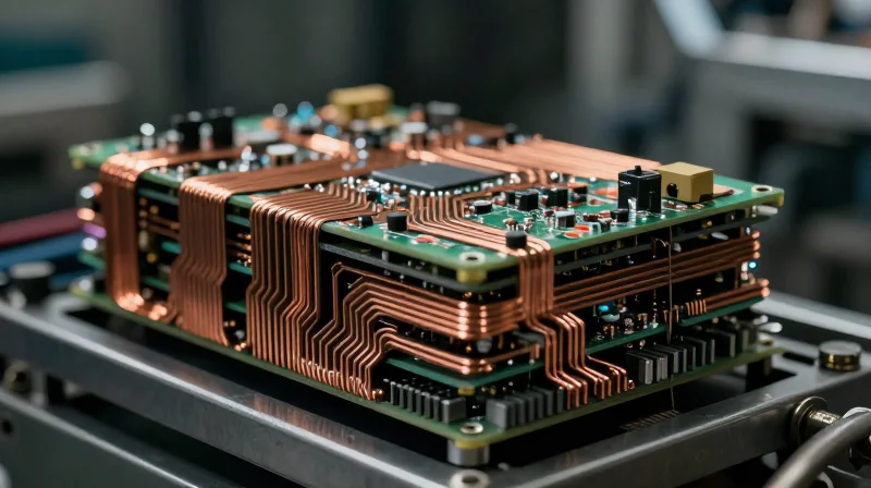
Designing printed circuit boards for industrial welding applications introduces a unique set of challenges that deviate significantly from consumer or standard commercial electronics. At the core of these challenges is the necessity for high current delivery, which necessitates heavy copper traces, and the unforgiving operational environment characterized by rapid thermal cycling and high-frequency electromagnetic interference.
Thermal Dynamics and Mechanical Stress
Welding machines operate in environments where power electronics must endure massive surges. The coefficient of thermal expansion (CTE) mismatch between the copper layers, the FR4 substrate, and the heavy power components creates mechanical stress during duty cycles. If the board construction is not balanced or if the manufacturer lacks expertise in high-temperature laminate materials, these stresses can lead to via cracking, delamination, or trace fracturing.
| Challenge | Standard PCB Impact | Welding PCB Requirement |
|---|---|---|
| Current Load | Traces overheat/vaporize | Heavy copper (3oz - 6oz+) |
| Thermal Cycling | Delamination/Cracks | High Tg laminates/Thermal vias |
| EMI/Noise | Signal interference/Failure | Advanced shielding/Ground planes |
Technical Considerations FAQ
- Why is 'heavy copper' problematic for standard manufacturers?
Standard etching processes struggle with high-aspect-ratio copper. Thick copper requires longer etch times, which can cause 'undercutting' and compromise the geometry and impedance control of critical signal traces. - How does high-frequency switching affect substrate selection?
Welding power supplies often use high-frequency PWM switching. Standard FR4 may have too high a dissipation factor (Df), leading to dielectric heating and performance degradation; specialized materials are often required.
Verifying Current-Carrying Capacity and Copper Weight
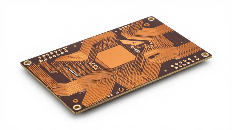
The Criticality of Thick-Copper Fabrication
For industrial welding machines, standard 1oz copper layers are insufficient. High-amperage current flow necessitates copper weights ranging from 2oz to 4oz or greater to minimize ohmic heating and prevent circuit board delamination. A manufacturer incapable of managing the etching challenges associated with these thicker traces will inevitably produce boards prone to premature failure under heavy thermal cycling.
Copper Weight vs. Thermal Load Capacity
| Copper Weight | Recommended Current (Max) | Primary Application |
|---|---|---|
| 1 oz | ~5-10 Amps | Control Logic Circuits |
| 2 oz | ~15-25 Amps | Intermediate Power Stages |
| 3 oz | ~30-50 Amps | Welding Power Inverter Drivers |
| 4 oz+ | 50+ Amps | High-Current Output Busbars |
Technical Considerations for High-Current Design
- Why does trace thickness affect etching?
As copper weight increases, the etch factor changes. A specialized manufacturer must compensate for undercut to ensure the trace width remains within tolerance, maintaining the intended current-carrying capacity without creating hotspots. - What is the importance of via filling?
For high-amperage boards, vias must be robustly plated. Improperly filled or undersized vias act as thermal bottlenecks, causing localized resistance that can lead to copper barrel cracking during the rapid thermal expansion cycles inherent in welding. - How does substrate material influence high-power reliability?
High-power welding boards require substrates with high Glass Transition Temperatures (Tg). When pairing thick copper with high-amperage loads, a high-Tg material prevents mechanical failure of the dielectric layer during continuous operation.
When auditing a potential PCB partner, verify their historical success with IPC-Class 3 standards. Their ability to deliver precision registration on heavy copper layers is the primary metric for ensuring your welding machine's long-term field reliability.
Essential Thermal Management Capabilities
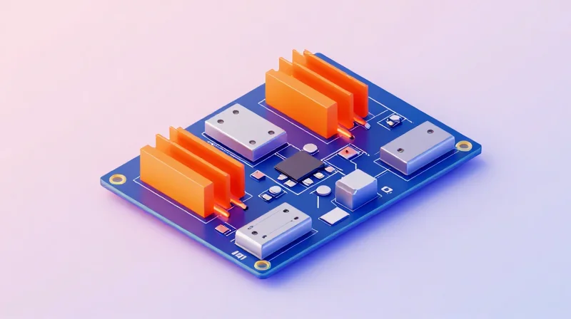
In high-power industrial welding, heat is the primary enemy of long-term system reliability. Because welding machines operate in high-current, high-temperature environments, selecting a PCB manufacturer that possesses advanced thermal management expertise is critical to preventing premature component failure and ensuring consistent arc stability.
Evaluating Substrate and Heat Dissipation Technologies
A capable manufacturer must offer more than standard FR-4 capabilities. For welding controllers, they should demonstrate proficiency in Metal Core PCB (MCPCB) integration and advanced thermal interface materials that facilitate rapid heat transfer away from high-power IGBTs and MOSFETs.
| Thermal Solution | Primary Application | Key Benefit |
|---|---|---|
| Aluminum-Backed Boards | High-Power Power Stages | Excellent heat dissipation with direct thermal contact |
| Thermal Vias (Filled/Capped) | PCB Interconnects | Vertical heat conduction to ground planes or heatsinks |
| High Tg FR-4 Materials | Logic & Control Circuits | Maintains structural integrity at elevated operating temps |
Frequently Asked Questions on Thermal Reliability
- Why are copper-filled thermal vias preferred over standard vias?
Copper-filled vias provide a solid thermal path, preventing the solder wicking issues common in standard plated-through holes and significantly increasing the thermal conductivity from the chip side to the bottom side of the board. - Does the manufacturer need special equipment for MCPCB production?
Yes, processing aluminum or copper-based substrates requires specialized CNC routing tools and bonding processes to ensure the dielectric layer remains intact and provides proper isolation without cracking. - How do I verify a manufacturer's thermal testing capabilities?
Request documentation on their DFM (Design for Manufacturing) review process regarding thermal layout, as well as evidence of their ability to perform cross-sectional analysis to verify internal via-fill quality.
Navigating Industry Standards and Certifications
The Critical Role of IPC-6012 Class 3 Compliance
For industrial welding machines, where equipment failure can result in significant downtime or safety hazards, meeting IPC-6012 Class 3 requirements is mandatory. Unlike standard consumer electronics, Class 3 signifies 'High Reliability Electronic Products,' ensuring the PCB can maintain continuous performance under harsh, fluctuating industrial environments. Manufacturers must demonstrate rigorous inspection criteria regarding plated-through-hole integrity, copper wrap, and dielectric spacing to prevent catastrophic delamination or electrical breakdown during high-current arcs.
Key Quality Certifications Compared
| Certification | Significance for Welding PCBs | Primary Benefit |
|---|---|---|
| ISO 9001 | Standard Quality Management Systems | Process consistency and accountability. |
| IPC-6012 Class 3 | Performance-based PCB construction | Reliability under thermal/physical stress. |
| IATF 16949 | Automotive-grade quality standards | Defect prevention and supply chain robustness. |
Why IATF 16949 Matters for Industrial Welding
While IATF 16949 is rooted in the automotive sector, its emphasis on defect prevention and continuous improvement is invaluable for high-power welding electronics. A manufacturer holding this certification is audited against stringent criteria that mimic the high-reliability demands of welding equipment, such as vibration resistance and long-term thermal endurance. Engaging a partner with this certification significantly reduces the risk of field failures due to poor solder joint fatigue or material instability.
Frequently Asked Questions
- Can a manufacturer use Class 2 standards for a welding machine?
While possible, it is highly discouraged. Class 2 allows for cosmetic imperfections and lesser structural integrity that often fail under the extreme heat cycling inherent to welding power supplies. - Is ISO 9001 sufficient on its own?
No. ISO 9001 manages general business processes; for welding applications, you must demand specific technical compliance to IPC-6012 Class 3 to ensure the physical PCB can handle high amperage. - Does a certification guarantee the board will work?
Certification is a baseline indicator of capability and quality culture, not a substitute for rigorous design-for-manufacturability (DFM) reviews and specific testing protocols.
Quality Assurance: From Raw Material to Finished Assembly

Establishing a Comprehensive Quality Assurance Framework
When manufacturing PCBs for high-power industrial welding machines, quality assurance (QA) must extend far beyond basic electrical testing. Because these systems operate under extreme voltage transients and intense thermal cycles, manufacturers must employ destructive and non-destructive testing methodologies that validate structural integrity and long-term reliability at every stage of the fabrication process.
Essential Verification Protocols
| Testing Protocol | Purpose for Welding Applications | Key Metric |
|---|---|---|
| Micro-section Analysis | Inspect internal layer registration and plating thickness. | Copper barrel thickness |
| Thermal Shock Testing | Simulates extreme temperature fluctuations in welding. | Interconnect integrity |
| Ionic Contamination | Detects residual residues causing dendrite growth. | Cleanliness levels |
| X-Ray Inspection | Validates internal solder joint and via alignment. | Defect detection rate |
Frequently Asked Questions regarding QA Protocols
- Why is micro-section analysis required for high-power boards?
Micro-sectioning allows the manufacturer to confirm that copper plating in the holes is thick and uniform enough to handle the massive current loads without cracking due to thermal expansion. - What frequency of thermal shock testing is standard?
For industrial welding equipment, boards should undergo standardized cycles (typically 100+ cycles) to ensure the coefficient of thermal expansion (CTE) mismatch between the copper, substrate, and components does not lead to premature field failure. - Does cleanliness testing really impact power performance?
Yes, residual conductive ionic contaminants can create leakage paths under high-voltage conditions, leading to catastrophic short-circuiting in high-amperage welding control circuits.
In conclusion, vetting a manufacturer's QA capability involves confirming they have an in-house laboratory equipped to perform these advanced analyses. A provider that relies solely on end-of-line electrical testing is insufficient for the rugged demands of industrial welding applications.
Supply Chain Stability and Scalability
Mitigating Supply Chain Volatility
Industrial welding equipment relies on specialized power components, such as high-current IGBTs and heavy-copper PCBs, which are susceptible to global supply fluctuations. A reliable manufacturing partner must possess a robust supply chain management system that proactively identifies potential bottlenecks, secures long-term agreements with material suppliers, and maintains strategic inventory buffers for critical long-lead-time components.
Scalability Requirements for Industrial Production
As production needs grow from prototyping to mass manufacturing, your PCB vendor must demonstrate the ability to scale output without compromising quality. This requires redundant production lines, advanced automation in component placement, and the capacity to shift workloads across multiple sites to ensure continuity during regional disruptions.
| Capacity Indicator | Low-Volume/Prototyping | High-Volume/Mass Production |
|---|---|---|
| Material Procurement | On-demand sourcing | Annual blanket contracts |
| Production Throughput | Manual or semi-auto | Fully automated SMT lines |
| Quality Oversight | Individual inspection | In-line AOI & flying probe |
Frequently Asked Questions: Supply Chain Readiness
- How do you verify a vendor's supply chain stability?
Request an audit report covering their sub-tier supplier vetting process and ask for their average lead-time variance metrics over the previous twelve months. - Why is 'Design for Manufacturing' (DFM) essential for scalability?
DFM ensures that component selection avoids obsolete parts and utilizes readily available footprints, which significantly lowers the risk of production stalls during volume ramps. - What is the importance of geographically diversified manufacturing?
Maintaining production capacity across different regions minimizes the risk of total supply chain failure caused by geopolitical tension, natural disasters, or logistics disruptions.
Case Study Analysis: Lessons from Field Failures
Case Study Analysis: Lessons from Field Failures
Field failures in high-power welding equipment are rarely the result of a single catastrophic event; rather, they are typically the culmination of incremental degradation due to poor material specification or inadequate design margins. By examining real-world failures, we can identify specific manufacturing pitfalls that lead to premature equipment retirement.
Common Failure Mechanisms
| Failure Mode | Primary Root Cause | Consequence |
|---|---|---|
| Dielectric Breakdown | Insufficient Creepage/Clearance | Arcing and Short Circuits |
| Pad Lifting/Delamination | Poor Tg (Glass Transition) Selection | Trace Separation under Vibration |
| CAF Formation | Low CTI Material Specification | Internal Shorts across Layers |
The most frequent issue involves Conductive Anodic Filament (CAF) growth. In high-power welding environments, moisture exposure combined with high bias voltages creates an ideal scenario for copper migration between through-holes. Manufacturers failing to use high-CTI (Comparative Tracking Index) base materials frequently witness boards failing within six months of deployment in humid industrial settings.
Strategic Takeaways for Procurement
- Why does thermal shock testing matter?
Welding cycles create massive localized heat fluctuations. Boards not tested for thermal fatigue will experience micro-cracking in plating, leading to intermittent signal failures. - How does trace spacing affect reliability?
Industrial machines suffer from dust accumulation. Tight spacing requires conformal coating; failure to account for this in design leads to surface tracking and inevitable catastrophic arcing. - Is laminate choice optional?
No. Standard FR-4 is insufficient for high-voltage power sections. Choosing high-Tg materials prevents structural instability during the extreme thermal cycling inherent in industrial welding.
Ultimately, the right manufacturer is one that proactively flags these design risks during the DFM (Design for Manufacturing) review process. If a supplier accepts a design without verifying its creepage requirements against your specific power levels, they are likely overlooking the very failures that disrupt your production line.
The Final Vetting Checklist for PCB Vendors
Essential Audit Criteria for High-Power PCB Partners
Selecting a manufacturer for high-power industrial welding applications requires moving beyond generic ISO certifications. You must verify their specific capability to handle high-copper-weight substrates, advanced thermal management, and strict IPC Class 3 assembly standards to prevent field failures.
| Vetting Category | Verification Requirement | Why It Matters |
|---|---|---|
| Material Competency | High-Tg/CTI laminates | Prevents delamination under extreme thermal cycling. |
| Copper Handling | 2oz+ copper processing | Critical for high-current paths and minimizing heat. |
| Quality Assurance | AOI and Flying Probe | Detects internal shorts and trace defects before deployment. |
| Trace Management | IPC-2221 compliance | Ensures proper creepage and clearance to prevent arcing. |
Final Onboarding Questions
- Can you provide documented experience with 2oz to 4oz inner layer copper weights?
Heavy copper is standard in welding gear; if a shop has limited experience here, the risk of etching inconsistencies and thermal stress failure increases. - What is your failure rate and containment process for complex high-power assemblies?
Look for a manufacturer that tracks DPMO (defects per million opportunities) and provides a clear CAPA (corrective and preventive action) report. - Does your thermal shock testing reflect the operational cycle of an industrial welder?
Ensure they can simulate the rapid heat-cool cycles inherent in welding, not just standard industry thermal testing. - Are you capable of maintaining supply chain transparency for critical components?
In high-power applications, counterfeit components can be catastrophic; demand verification of authorized distribution channels.
Ultimately, your manufacturer should function as an extension of your engineering team. If a prospective vendor is unwilling to engage in a technical audit or provide detailed process capability reports, they are likely not equipped to support the reliability requirements of industrial-grade welding equipment.
Selecting a PCB partner for industrial welding equipment is a strategic decision that impacts the longevity and safety of your products. By prioritizing partners with demonstrated expertise in high-current thermal management and rigorous certification standards, you minimize risk and optimize performance. Ready to secure your supply chain? Contact our engineering team today to discuss your next high-power PCB requirement.
