
With the transition to WiFi 6 and the explosion of WiFi 7, MIMO router designs face unprecedented signal integrity challenges. Choosing the wrong substrate can result in catastrophic insertion loss and thermal failure. This guide breaks down the mission-critical factors engineers must evaluate to guarantee high-frequency performance.
Understanding the High-Frequency Demands of WiFi 6 and 7

The 6GHz+ Paradigm Shift
WiFi 6E and WiFi 7 have extended the operational spectrum into the 6GHz band, introducing significantly tighter signal integrity margins and increased sensitivity to parasitic losses. At these higher frequencies, the dielectric constant (Dk) and dissipation factor (Df) of the substrate are no longer negligible constants; they become dominant factors in determining total system efficiency, thermal stability, and effective throughput.
The Failure of Legacy FR-4
Traditional FR-4, the industry standard for decades, is fundamentally ill-suited for modern high-performance routers. Its inconsistent dielectric properties and high dissipation factor lead to significant signal attenuation and phase distortion at frequencies exceeding 5GHz. Designers attempting to utilize FR-4 in WiFi 7 designs often face catastrophic signal-to-noise ratio degradation and unpredictable thermal expansion.
| Parameter | Standard FR-4 | High-Frequency Laminate | Impact on WiFi 7 |
|---|---|---|---|
| Dielectric Constant (Dk) | 4.4 - 4.8 | 3.0 - 3.7 | Reduced signal delay |
| Dissipation Factor (Df) | 0.015 - 0.020 | < 0.005 | Lower insertion loss |
| Thermal Expansion | High | Low | Improved reliability |
Key Engineering Considerations
- Why is a low Dissipation Factor (Df) critical?
A low Df minimizes signal energy conversion into heat, ensuring that more power reaches the antenna rather than being lost as dielectric heating at 6GHz frequencies. - How does Dielectric Constant (Dk) stability affect routing?
Stable Dk allows for precise impedance control across high-speed traces, preventing signal reflections that can cause jitter and throughput throttling in multi-gigabit Wi-Fi streams. - Does thermal performance matter for WiFi 7?
Yes; the increased processing load and higher frequency operation generate concentrated heat, requiring substrates with superior thermal conductivity to prevent delamination and impedance drift.
The Role of Dielectric Constant (Dk) Stability
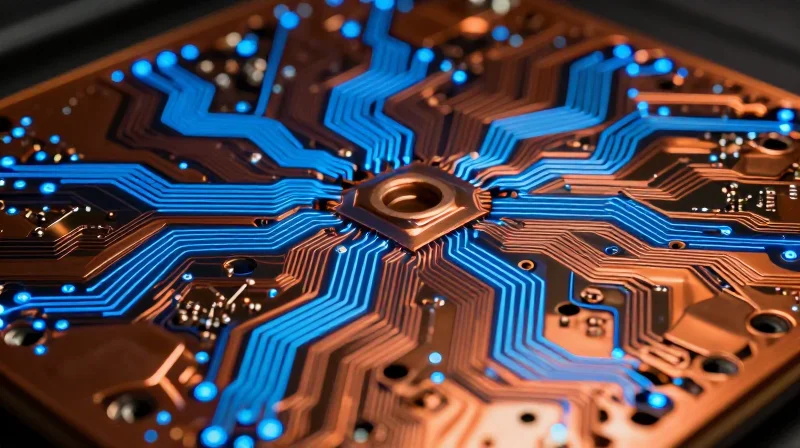
The Criticality of Dk Stability in MIMO Architectures
In WiFi 6 and 7 routers, the reliance on Multiple-Input Multiple-Output (MIMO) technology mandates precise phase synchronization across all antenna elements. The Dielectric Constant (Dk) of the PCB substrate directly influences signal propagation velocity. If the Dk fluctuates due to thermal changes or frequency variance, it induces unpredictable phase shifts across the array. Even minor deviations can lead to destructive interference, significantly reducing spatial multiplexing efficiency and overall throughput.
Thermal and Frequency-Dependent Variations
WiFi 7 devices often operate in thermally constrained environments, such as high-density home or enterprise routers. Traditional substrates like standard FR-4 exhibit a significant Thermal Coefficient of Dielectric Constant (TCDk), causing the Dk to drift as the router heats up. This drift is exacerbated at the higher 6GHz+ frequencies, where wavelength becomes extremely short and sensitivity to substrate composition increases.
| Material Property | Standard FR-4 | High-Speed PTFE/Ceramic |
|---|---|---|
| Dk Stability (Thermal) | Low (High TCDk) | High (Low TCDk) |
| Signal Loss (Df) | High (>0.015) | Very Low (<0.003) |
| MIMO Phase Accuracy | Poor | Excellent |
- Why does frequency affect Dk?
As frequency increases into the GHz range, the molecular polarization response of the resin system changes, often leading to a non-linear drop in Dk that can distort high-speed signal integrity. - How does TCDk impact user experience?
Poor TCDk results in signal beamforming errors in WiFi 6/7, leading to dropped packets, increased latency, and a reduced effective coverage range for the end user.
To ensure reliable performance in the 6GHz band, designers must prioritize low-loss laminates that offer a flat Dk profile. Selecting materials with a controlled Dk, often glass-reinforced PTFE or advanced hydrocarbon ceramic-filled laminates, provides the consistent impedance and phase velocity necessary for advanced modulation schemes like 4096-QAM.
Minimizing Loss Tangent (Df) for Signal Integrity
In the context of WiFi 6 and 7, where signals frequently operate at 6 GHz and beyond, the dissipation factor (Df), also known as the loss tangent, acts as the primary governor of signal attenuation. As electromagnetic waves propagate through the PCB substrate, a portion of the signal energy is absorbed by the dielectric material and dissipated as heat. For high-performance routing, selecting a substrate with ultra-low Df is not just a performance enhancement but a requirement to maintain the link budget and ensure the signal-to-noise ratio remains sufficient for complex modulation schemes like 4096-QAM.
Material Performance Comparison for High-Frequency Designs
| Material Category | Typical Df (@10GHz) | Suitability |
|---|---|---|
| Standard FR-4 | 0.020 | Unsuitable |
| High-Tg/Mid-Loss Laminate | 0.008 - 0.010 | Limited |
| Ultra-Low Loss PTFE/Ceramic | 0.001 - 0.003 | Ideal |
Minimizing Insertion Loss in Multi-Gigabit Routing
Insertion loss is a function of both dielectric loss (governed by Df) and conductor loss (governed by copper surface roughness). At frequencies used in WiFi 7, even a minor difference in Df can result in several decibels of loss over a standard trace length. To mitigate this, design engineers must prioritize materials where the resin systems have been engineered for molecular stability. Using substrates that minimize dielectric absorption ensures that the high-frequency harmonics of the digital signal remain intact, preventing the eye diagram closure that would otherwise lead to bit error rate (BER) degradation.
Frequently Asked Questions on Loss Tangent
- How does Df affect WiFi 7 data throughput?
A high Df causes significant signal attenuation, which forces the router to drop to lower MCS indices, reducing the overall data throughput and range of the device. - Is Df the only factor for signal loss?
No, conductor loss from skin effect and surface roughness of the copper foil also contributes significantly to total insertion loss alongside the substrate's Df. - Why does frequency matter when selecting Df?
Dissipation factors are not constant; they typically increase with frequency. It is critical to select a material with a stable, flat Df profile across the entire operating range of the WiFi bands.
Thermal Management and Glass Transition Temperature (Tg)
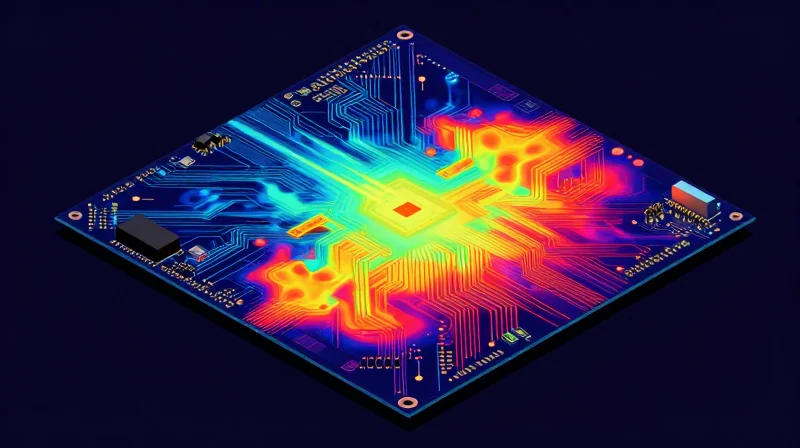
Understanding the Impact of Tg in High-Density Routers
As WiFi 6 and 7 routers integrate more high-power processing cores and multi-band radio front-ends, the board experiences localized 'hot spots.' The Glass Transition Temperature (Tg) represents the threshold at which a polymer matrix transitions from a rigid, glassy state to a softer, rubbery state. Operating near or above this temperature causes a significant increase in the Coefficient of Thermal Expansion (CTE), leading to mechanical stress on copper traces, via cracking, and potential delamination of the dielectric.
Thermal Performance Comparison
| Material Class | Typical Tg (°C) | Thermal Suitability | WiFi Application |
|---|---|---|---|
| Standard FR-4 | 130-140 | Poor | Legacy Low-Power |
| High-Tg FR-4 | 170-180 | Moderate | Entry-level WiFi 6 |
| High-Performance Laminate | 200+ | Excellent | WiFi 7 / High-Density |
Thermal Management Strategies
While a high Tg material provides structural stability, superior thermal conductivity is required to dissipate heat away from critical WiFi 7 chipsets. Substrates with inorganic fillers, such as ceramic-filled PTFE or specialized epoxy resins, significantly improve thermal dissipation. This reduces the operating temperature of the ICs, extending component lifespan and ensuring the dielectric properties remain stable during intensive data throughput.
- Why does a high Tg matter for WiFi 7?
WiFi 7 routers handle higher power densities; high-Tg materials prevent the substrate from softening, which protects internal copper structures from thermal expansion fatigue. - How does thermal conductivity affect signal integrity?
Excessive heat causes localized Dk drifting. Efficient thermal management keeps the substrate cool, ensuring the dielectric constant remains stable and signal impedance does not shift. - Is standard FR-4 sufficient for modern routers?
No. Standard FR-4 lacks the thermal reliability to handle the heat dissipation requirements of current high-frequency, high-data-rate WiFi platforms, risking long-term reliability issues.
Copper Surface Roughness and Skin Effect Considerations
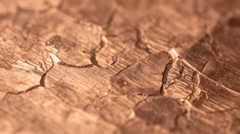
The Impact of Copper Profile on Skin Effect
At WiFi 6 and 7 frequencies, the skin effect causes high-speed signals to travel primarily along the outer surface of the copper trace. When the copper foil profile is rough—characterized by large nodules used for mechanical adhesion—the signal path is artificially lengthened, increasing effective resistance and insertion loss. For high-performance router designs, utilizing VLP (Very Low Profile) or HVLP (Hyper Very Low Profile) copper is mandatory to minimize these resistive losses.
| Copper Grade | RMS Roughness (Rq) | Suitability for WiFi 6/7 |
|---|---|---|
| Standard Electro-Deposited (STD) | 2.0 - 3.0 µm | Poor - High signal attenuation |
| Very Low Profile (VLP) | 0.8 - 1.2 µm | Good - Standard for high-speed |
| Hyper Very Low Profile (HVLP) | < 0.5 µm | Excellent - Optimal for 6GHz+ bands |
Copper Roughness FAQs
- Why does copper roughness affect insertion loss?
As frequency increases, the skin depth decreases, forcing more current density into the rough topology at the copper-dielectric interface, leading to increased ohmic losses. - Does ultra-low profile copper affect PCB reliability?
While smoother copper can present challenges for bond strength between the metal and the dielectric, modern resin systems are engineered to chemically bond with low-profile foils, maintaining high peel strength without needing mechanical anchoring. - Is HVLP copper necessary for the 2.4GHz band?
No, HVLP is primarily required for the 5GHz and 6GHz bands used in WiFi 6E and 7; standard low-profile copper is often sufficient for lower frequency bands.
Navigating Industry Standards and Certifications
Navigating Industry Standards and Certifications
Achieving commercial viability for WiFi 6 and 7 hardware requires strict adherence to industry standards that govern material safety, reliability, and signal integrity. Manufacturers must move beyond general-purpose laminates and select materials that possess verified certifications, ensuring the product can endure the demanding thermal and electrical profiles of multi-gigabit wireless systems.
Essential Compliance Standards for High-Frequency PCBs
- UL 94 Flammability Rating
A minimum rating of UL 94 V-0 is mandatory for almost all commercial routing equipment. It signifies that the PCB material effectively self-extinguishes upon ignition, providing the necessary safety profile for end-user consumer electronics. - IPC-4101 Specification
The primary industry standard for rigid and multilayer boards. Look for materials categorized under slash sheets that align with high-frequency requirements, ensuring predictable dielectric constant (Dk) and dissipation factor (Df) stability across different batch productions. - IPC-6012 Performance Class
For high-performance WiFi equipment, design teams should mandate IPC-6012 Class 2 or Class 3 qualification to ensure the board's structural integrity and thermal reliability under sustained operational loads.
Comparative Certification Requirements
| Certification | Purpose | Significance for WiFi 7 |
|---|---|---|
| UL 94 V-0 | Flammability | Critical for market safety and legal compliance. |
| RoHS/REACH | Environmental | Global trade requirement; ensures lead-free assembly processes. |
| IPC-4101/126 | Material Stability | Defines consistency in high-frequency dielectric performance. |
Strategic Sourcing Tips
To mitigate risk, ensure that your substrate provider provides comprehensive documentation including Certificate of Conformance (CoC) and batch-specific test reports. For high-speed WiFi 7 designs, prioritize vendors who offer 'Ultra-Low Loss' materials that are pre-certified for high-speed digital applications, as this reduces the burden of additional qualification cycles during the prototyping phase.
Cost-Performance Trade-offs in Laminate Selection
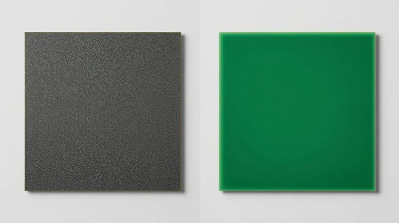
In the development of WiFi 6 and 7 consumer equipment, the selection of substrate materials is often a compromise between the theoretical electrical performance of PTFE-based materials and the economic realities of high-volume manufacturing. While high-frequency performance demands low dissipation factors (Df), these materials often introduce challenges in processing, drilling, and mechanical stability that inflate total cost of ownership.
Economic Implications of Substrate Tiers
| Material Class | Performance Level | Relative Cost | Application Suitability |
|---|---|---|---|
| Standard FR-4 | Low (High Df) | Baseline | Low-frequency legacy support only |
| High-Tg / Mid-Loss | Moderate | 1.5x - 2x | Mainstream WiFi 6 routers |
| Hydrocarbon Ceramic | High | 3x - 5x | WiFi 7 / High-performance beamforming |
| PTFE-based Laminates | Ultra-High | 8x+ | Enterprise / Infrastructure backhaul |
Balancing Performance and Budget
Engineers should prioritize material selection by quantifying the actual signal integrity budget. If target throughput can be maintained through clever PCB layout and shorter signal paths, transitioning from expensive PTFE to a high-performance hydrocarbon-filled thermoset laminate can reduce substrate costs by over 40% without sacrificing essential WiFi 7 performance.
- Can I use FR-4 for WiFi 7 designs?
Standard FR-4 is generally unsuitable for the 6GHz and 7GHz bands due to excessive dielectric loss; consider hybrid constructions where only critical RF layers use high-frequency laminates. - How does manufacturing complexity affect cost?
PTFE laminates require specialized plasma etching and chemical desmear processes which increase fabrication cycle times and reject rates compared to standard glass-reinforced materials. - Is board-level shielding a cost-effective alternative to expensive substrates?
Yes, investing in high-quality mechanical shielding and optimizing component placement can often allow for the use of mid-tier materials, potentially saving thousands in unit-cost at scale.
Best Practices for Prototyping and Validation
Bridging Simulation and Reality
For WiFi 6 and 7, where frequencies reach 6GHz and 7.125GHz respectively, theoretical material properties are often insufficient to predict final system performance. Engineers must utilize 3D electromagnetic (EM) field solvers to model the behavior of the dielectric constant (Dk) and dissipation factor (Df) under specific board geometries. By integrating these simulations into the early prototyping phase, you create a baseline for expected signal integrity, ensuring that chosen laminates like hydrocarbon-ceramics behave as intended before full-scale manufacturing begins.
Validation Strategies: Coupons and Prototyping
The implementation of test coupons is the most critical safeguard for verifying substrate integrity. By placing specialized structures on the panel edges—such as Time Domain Reflectometry (TDR) traces and Insertion Loss coupons—designers can directly measure impedance stability and signal loss without needing to probe complex routing layers. These coupons act as a bridge between the virtual model and the physical product.
| Validation Method | Key Metric | Primary Goal |
|---|---|---|
| EM Simulation | S-Parameters | Identify resonant modes and discontinuities. |
| TDR Coupons | Impedance (Ohms) | Verify consistent trace manufacturing. |
| Insertion Loss Coupons | dB/inch | Validate material loss targets. |
| Environmental Stress Test | Dk Stability | Evaluate performance under temperature swings. |
Key Considerations for WiFi 7 Validation
- Should I test for moisture absorption?
Yes. WiFi 7 routers are often used in varied environmental conditions; high moisture absorption in a substrate can significantly shift the Dk and degrade signal phase, leading to failures in high-order modulation schemes like 4096-QAM. - Why perform thermal cycling during prototyping?
Materials behave differently during thermal expansion. WiFi 7 components dissipate significant heat; validating your substrate's Coefficient of Thermal Expansion (CTE) prevents long-term reliability issues and signal drift caused by mechanical stress. - How does surface finish impact validation?
Surface finishes like ENIG or Immersion Silver alter skin effect losses. Your validation coupons must use the same surface finish as your final production boards, or your test data will not accurately reflect real-world insertion loss.
Ultimately, the transition from prototype to mass production should be marked by a 'Golden Coupon' baseline. Once you have confirmed that your simulation matches the physical measurement of your prototype coupons, lock these parameters into your manufacturing specification to ensure consistency across every batch of WiFi-ready router PCBs.
Selecting the right PCB substrate is a foundational decision that dictates the success of your MIMO router design. By prioritizing dielectric stability and thermal reliability, you ensure your device stands out in the competitive WiFi 7 market. Ready to optimize your high-speed hardware? Contact our engineering team today for a custom material consultation.
