
In the high-stakes world of industrial automation, your Variable Frequency Drive (VFD) is only as reliable as the printed circuit board at its heart. With rising power densities and harsh environmental stressors, selecting the wrong fabrication partner can lead to catastrophic failure. This guide empowers engineers and procurement leads to vet suppliers based on technical rigor, thermal resilience, and industry-standard compliance.
The Unique Demands of VFD Circuitry
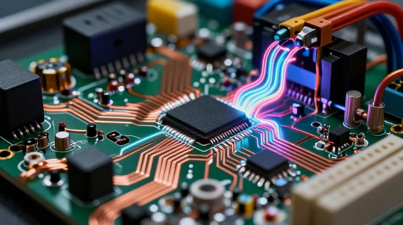
The Engineering Reality of VFD Circuitry
Variable Frequency Drives (VFDs) push PCB technology to its absolute limit by combining high-power switching with sensitive control signal integrity. Unlike standard consumer electronics, VFD circuitry must manage fast-rising edge signals (dv/dt) generated by Insulated Gate Bipolar Transistors (IGBTs), which create significant electromagnetic interference (EMI) and voltage spikes. Precision manufacturing is not merely a preference; it is a necessity to prevent parasitic capacitance, inductive noise, and thermal runaway that can lead to catastrophic motor system failure.
Key Design Challenges
| Challenge Factor | Impact on PCB Design | Manufacturing Requirement |
|---|---|---|
| High dv/dt Switching | Excessive EMI and voltage overshoot | Advanced layer stack-up and shielding |
| High Power Density | Localized heat concentration | Heavy copper weights and thermal vias |
| Voltage Clearance | Potential for arcing between traces | Precision routing and creepage compliance |
Common Technical Queries
- Why is copper weight critical for VFD boards?
VFDs often manage high current paths. Using heavier copper (2oz or more) reduces resistive losses and minimizes heat generation, ensuring the board can handle sustained power throughput without degradation. - How does PCB layout affect EMI in motor control?
Poor loop area management in gate driver circuits leads to massive EMI. Professional manufacturers prioritize trace impedance matching and short, optimized return paths to keep switching noise localized. - What role do insulation materials play?
Given the high voltage nature of VFDs, the PCB must utilize high-Tg (Glass Transition Temperature) and high-CTI (Comparative Tracking Index) laminates to prevent dielectric breakdown and ensure safety under fluctuating industrial temperatures.
Prioritizing Thermal Management Capabilities
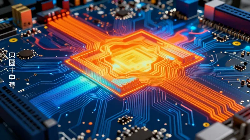
Core Thermal Management Requirements
In precision VFD systems, heat is the primary enemy of component longevity. A manufacturer must demonstrate proficiency in handling high-current loads through robust copper architectures. If a fabricator cannot guarantee consistent copper plating thickness or reliable thermal via array performance, the PCB will likely experience localized hotspots, leading to premature dielectric breakdown and catastrophic system failure.
Comparing Thermal Dissipation Techniques
| Technology | Best Use Case | Manufacturing Complexity |
|---|---|---|
| Heavy Copper (3oz+) | High-current power stages | Moderate |
| Thermal Vias | Heat transfer to planes | Low |
| Embedded Heatsinks | Extreme power density | High |
Evaluating Fabrication Capabilities
When auditing a potential PCB partner, focus on their process control regarding stack-up symmetry and thermal conductivity materials. A manufacturer should be able to provide documentation on their ability to maintain thermal pad alignment under high-temperature reflow cycles, which is critical for precision VFD operation.
- Can they handle 4oz copper weights reliably?
Ensure the manufacturer uses specialized etching processes to prevent undercut or excessive width reduction in heavy copper traces. - Do they offer filled and capped thermal vias?
Using via-in-pad technology that is both filled and capped is essential for preventing solder wicking and ensuring optimal thermal pathing. - How do they manage CTE mismatch?
A high-quality partner will select substrate materials with a Coefficient of Thermal Expansion (CTE) that minimizes stress on solder joints during rapid thermal cycling.
Material Selection for High-Voltage Switching
Material Selection for High-Voltage Switching
In high-voltage Variable Frequency Drive (VFD) systems, the PCB substrate serves as the primary barrier against dielectric breakdown and thermal fatigue. As switching frequencies increase, standard FR-4 materials often fail to manage the cumulative effects of heat generation and high-speed electrical stress, leading to delamination or trace lift. Selecting a manufacturing partner with expertise in specialized laminates is therefore essential to ensure long-term operational stability in demanding industrial environments.
Key Material Characteristics for Reliability
| Material Property | Significance for VFD | Impact on Performance |
|---|---|---|
| Glass Transition (Tg) | Thermal threshold resilience | Prevents warping and substrate cracking |
| Dissipation Factor (Df) | Dielectric energy loss | Reduces heating at high frequencies |
| Dielectric Strength | Insulation breakdown voltage | Prevents arcing between high-voltage nodes |
| Coefficient of Thermal Expansion (CTE) | Dimensional stability | Ensures reliable barrel plating in vias |
When evaluating potential manufacturers, verify their experience with high-Tg (170°C+) laminates and low-loss dielectrics. These materials provide the necessary structural integrity for boards subject to the intense temperature cycling inherent in motor control loops. A competent manufacturer will not only source these materials but also provide data on their performance during simulated harsh environment testing.
- Why is high-Tg laminate essential for VFDs?
VFDs operate under continuous switching loads that cause rapid temperature fluctuations; high-Tg materials retain their mechanical properties at these elevated temperatures, preventing structural failure. - How does dielectric loss affect system efficiency?
Lower dielectric loss (Df) minimizes signal attenuation and self-heating within the substrate, which is crucial for high-voltage switching efficiency and preventing localized 'hot spots'. - What should I look for in a manufacturer's material certification?
Look for compliance with UL 94V-0 flammability standards and documentation regarding CTI (Comparative Tracking Index) ratings, which determine how well the board resists conductive tracking under high voltages.
Ensuring Signal Integrity and EMI Control

Engineering Signal Integrity in High-Noise Environments
In industrial motor control, Variable Frequency Drives generate significant electromagnetic interference (EMI) due to high-speed PWM switching. A top-tier manufacturer must prioritize a multilayer stack-up that optimizes return paths and minimizes loop area. Manufacturers should employ simulation tools to verify impedance tolerances before fabrication, ensuring that sensitive gate-drive signals remain shielded from the high-power switching nodes that cause crosstalk.
Comparative Strategies for EMI Mitigation
| Design Technique | Purpose | Impact on Performance |
|---|---|---|
| Controlled Impedance | Matches trace impedance to component requirements | Reduces signal reflections and ringing |
| Solid Ground Planes | Provides a continuous low-inductance return path | Minimizes electromagnetic emission loop area |
| Staggered Via Placement | Prevents vertical noise coupling between layers | Ensures cleaner signal integrity in high-density areas |
Frequently Asked Questions on VFD EMI Control
- Why is layer stack-up symmetry critical for VFDs?
Symmetrical stack-up prevents mechanical board warpage during the thermal cycling characteristic of industrial drives, while also ensuring consistent dielectric spacing for uniform impedance across the board. - How does the manufacturer verify impedance compliance?
A qualified manufacturer uses Time Domain Reflectometry (TDR) testing on test coupons included on the production panel to guarantee that actual impedance matches the design intent. - What role do guard traces play in motor control?
Guard traces act as a Faraday shield for sensitive feedback signals, isolating them from high-dv/dt noise nodes and preventing false triggering of protection circuits.
Verifying IPC Compliance and Quality Standards
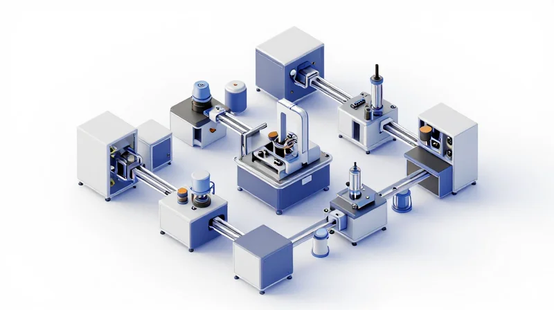
The Imperative of IPC-6012 Class 3 Standards
In the context of industrial motor control, where downtime translates into massive financial loss or safety hazards, meeting IPC-6012 Class 3 criteria is the baseline for performance. Unlike standard commercial boards, Class 3 manufacturing mandates more stringent inspections, tighter tolerances on hole wall plating, and superior solder mask adhesion. A manufacturer that operates without formal certification to these standards risks catastrophic board failure under the constant vibration and high-thermal-stress conditions typical of VFD applications.
Quality Benchmarks for VFD PCB Fabrication
| Quality Parameter | Class 2 Standard | Class 3 (Mission-Critical) |
|---|---|---|
| Minimum Plating Thickness | 20 micrometers | 25 micrometers |
| Inspection Frequency | Statistical Sampling | 100% Automated Optical/X-Ray |
| Thermal Shock Resilience | Standard Cycles | Extended Stress Testing |
Verifying Manufacturer Qualifications
Verification must go beyond a simple certificate on a website. You must audit the manufacturer’s internal quality control processes and ensure they maintain real-time data tracking for every batch produced.
- How do you verify IPC-6012 compliance?
Request the manufacturer's Certificate of Conformance (CoC) and evidence of their most recent third-party audit performed by an IPC-certified trainer or independent auditing body. - Why is Automated Optical Inspection (AOI) critical?
VFD boards involve dense power circuitry; AOI identifies micro-shorts and trace imperfections that human inspectors often miss, ensuring long-term reliability under electrical load. - Is ISO 9001 enough?
While ISO 9001 proves general management competence, it does not guarantee the technical execution required for complex power electronics. Always insist on specific IPC certification.
Analyzing Vendor Quality Certifications
The Hierarchical Importance of Certifications
Not all certifications carry the same weight for high-reliability motor control applications. While base-level compliance indicates a functional quality management system (QMS), advanced industry-specific certifications serve as proxies for a manufacturer’s commitment to process consistency, traceability, and risk management in extreme environments.
| Certification | Primary Focus | Relevance to VFD PCBs |
|---|---|---|
| ISO 9001 | General Quality Management | Essential baseline for process documentation. |
| IATF 16949 | Automotive Quality | Critical for high-volume reliability and defect prevention. |
| AS9100 | Aerospace Quality | Highest standard for rigorous risk management and traceability. |
Evaluating Manufacturer Quality Standards
- Why is IATF 16949 a differentiator for industrial VFDs?
Originally designed for the automotive sector, IATF 16949 emphasizes robust failure mode and effects analysis (FMEA) and statistical process control, which are vital for mitigating PCB failures in vibration-prone industrial settings. - Does AS9100 provide added value for non-aerospace hardware?
Yes. AS9100 builds upon ISO 9001 with strict requirements for supply chain transparency and counterfeit part prevention, ensuring that every raw material—from laminate to solder paste—is fully qualified. - How should I verify a vendor's claims?
Always request current, valid certificates directly from the registrar's portal. Ensure the scope of their certification explicitly covers the manufacturing facility producing your specific PCB technology.
By prioritizing manufacturers who hold these certifications, you shift the burden of quality control from post-production inspection to process-driven prevention, significantly lowering the risk of field failures in motor control systems.
DFM Review and Prototyping Support

The Strategic Value of DFM Review
Design for Manufacturing (DFM) is not merely a checklist; it is a proactive engineering audit that identifies potential fabrication bottlenecks before the first board is etched. For precision VFD PCBs, where high-current traces and sensitive gate-drive circuitry coexist, DFM analysis prevents common pitfalls such as inadequate annular rings, thermal relief issues, and problematic aspect ratios in via drilling. Engaging a manufacturer that provides comprehensive DFM feedback shifts the focus from 'will this build?' to 'will this last in a motor control environment?'
Prototyping as an Iterative Risk Mitigation Tool
Prototyping serves as the physical validation of the theoretical design. In the context of variable frequency drives, prototyping support goes beyond basic assembly; it involves evaluating how the layout handles high-frequency switching transients and heat dissipation under load. A manufacturer that offers agile prototyping services allows for the verification of thermal management strategies and EMI shielding effectiveness, which are often the primary failure points in industrial motor control systems.
| Feature | Reactive Production Approach | Integrated DFM & Prototyping Partner |
|---|---|---|
| Design Issues | Found during mass production (expensive scrap) | Identified and corrected in DFM stage |
| Lead Times | Extended by repeated engineering holds | Optimized via early design validation |
| Reliability | Risk of field failures in motor drives | Enhanced through design-for-reliability audits |
Key Considerations for DFM Integration
- Does the vendor provide automated DFM feedback?
Ensure the manufacturer uses advanced CAM software to automatically flag trace-to-hole spacing, copper balance, and impedance discontinuities. - What level of engineering support is available during prototyping?
Select a partner who assigns a dedicated DFM engineer to review your Gerbers and provide specific recommendations for panelization and substrate selection. - Is there a feedback loop between prototyping and mass production?
Verify that the manufacturer uses lessons learned from initial prototypes to update the manufacturing recipe, ensuring a seamless transition to high-volume production.
Supply Chain Stability and Long-Term Partnership
Assessing Financial and Operational Viability
A manufacturer’s longevity is often tied to its financial health and operational agility. For precision VFD (Variable Frequency Drive) PCB projects, you must ensure your partner possesses the capital depth to sustain high-mix, low-volume production or handle rapid scaling without compromising quality. Partners that have weathered multiple economic cycles demonstrate the fiscal responsibility required to maintain advanced equipment and retain skilled engineering staff.
Component Sourcing and Resilience Strategies
Supply chain transparency is the backbone of industrial reliability. When sourcing critical components for VFD systems—such as high-voltage capacitors, gate drivers, and isolation transformers—a capable manufacturer must have proactive strategies to combat obsolescence and supply volatility. Look for partners who maintain direct relationships with authorized distributors and have formal mechanisms for PCN (Product Change Notification) management.
| Risk Factor | Assessment Metric | Strategic Mitigation |
|---|---|---|
| Financial Instability | D&B Rating / Annual Revenue | Multi-year contract lock-ins |
| Component Obsolescence | End-of-Life (EOL) tracking system | Last-time-buy planning |
| Supply Chain Disruption | Multi-sourcing capability | Strategic inventory buffer |
Frequently Asked Questions on Partnership Stability
- How do I verify if a manufacturer is financially secure?
Request an overview of their annual capital investment in manufacturing equipment and perform a standard credit check to assess their ability to support long-term production requirements. - What role does local vs. global sourcing play in my PCB supply chain?
Global sourcing offers cost advantages but increases logistical risk; high-reliability VFDs often benefit from a hybrid model where critical components are sourced from geographically diverse, authorized distributors to minimize lead-time shocks. - How does a manufacturer handle sudden component shortages?
A robust partner will provide a dedicated supply chain manager who monitors risk reports, suggests verified cross-references for immediate approval, and maintains a buffer of long-lead-time items.
Ultimately, selecting a manufacturer for precision VFD PCBs is about transitioning from a transactional mindset to a strategic partnership. By prioritizing vendors that emphasize supply chain transparency and financial health, you ensure the long-term continuity of your industrial motor control systems.
Selecting a VFD PCB manufacturer is a strategic decision that directly impacts the longevity and safety of your industrial motor control systems. By prioritizing technical expertise, material quality, and stringent quality certifications, you can mitigate operational risks and ensure peak performance. Contact our engineering team today to discuss how we can support your next high-power VFD design project with precision fabrication solutions.
