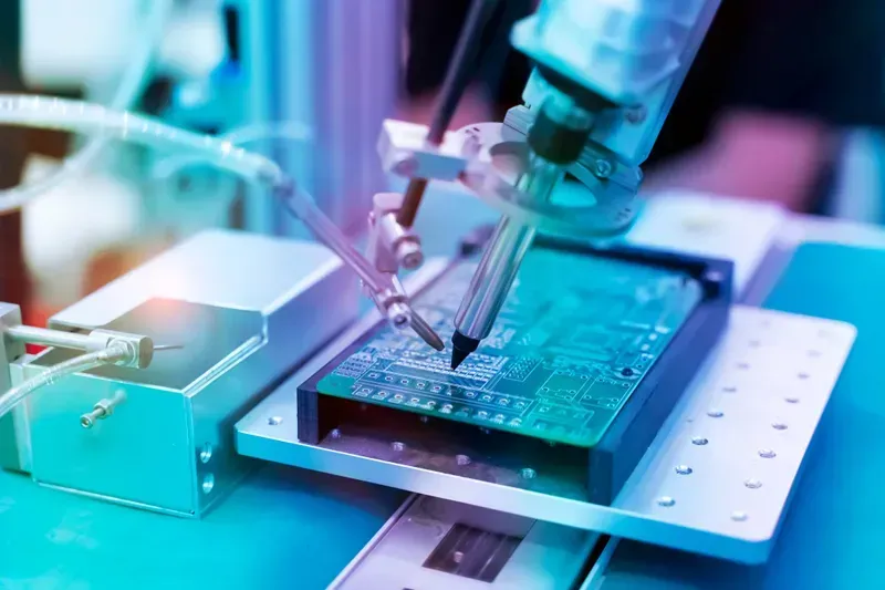
In the relentless pursuit of automation and precision, industrial welding robots stand as pillars of modern manufacturing. These sophisticated machines demand equally sophisticated control systems, and at the heart of these systems lies the Printed Circuit Board (PCB). A welding robot's PCB isn't just a component; it's the brain orchestrating precise movements, managing power distribution, and ensuring seamless communication between various modules. The reliability and efficiency of these PCBs directly impact the welding robot's performance, uptime, and ultimately, the quality of the weld itself. At Zero One Solution, we understand the critical role of high-quality PCBs in industrial welding robots. Our comprehensive PCB solutions are engineered to meet the demanding requirements of this sector, ensuring precision, reliability, and longevity. This article delves into the intricacies of PCB solutions for industrial welding robots, exploring design considerations, manufacturing processes, and the critical importance of robust performance.
Introduction: The Vital Role of PCBs in Industrial Welding Robots
Printed Circuit Boards (PCBs) are the unseen backbone of industrial welding robots, serving as the central nervous system that orchestrates every precise movement and critical function. Their quality directly dictates the robot's performance, reliability, and ultimately, the efficiency and safety of the entire welding operation. Without robust and intelligently designed PCBs, the advanced capabilities of modern welding robots—from intricate arc control to sophisticated motion sequences—would simply not be possible.
Why are PCBs so critical for welding robots? PCBs are the foundational platform for all electronic components within a welding robot, enabling complex computations, precise motor control, sensor data interpretation, and communication between various subsystems. They translate high-level programming into actionable commands for welding torches, manipulators, and safety mechanisms.
How does PCB quality impact robot performance? High-quality PCBs ensure signal integrity, minimizing data loss or interference that can lead to imprecise welds, operational errors, or even system failures. Superior thermal management on the PCB prevents overheating of critical components, prolonging the robot's lifespan and maintaining consistent performance during demanding industrial cycles. A well-designed PCB also offers enhanced resistance to the harsh environmental conditions prevalent in welding environments, such as high temperatures, vibrations, and electromagnetic interference (EMI).
PCB Aspect
Impact on Welding Robot Performance
Risk of Poor Quality
Signal Integrity
Precise control of welding parameters (current, voltage, speed)
Designing Printed Circuit Boards (PCBs) for industrial welding robots demands a meticulous approach, as these components are the neural centers orchestrating complex robotic movements and welding processes. The inherent harshness of industrial welding environments
—characterized by extreme temperatures, intense vibrations, and electromagnetic interference
—necessitates a robust design paradigm. Beyond mere functionality, the longevity and reliability of the entire robotic system hinge on how effectively these PCBs are engineered to withstand such demanding conditions. Critical design considerations encompass thermal management to dissipate heat generated by high-power components, robust mechanical design to resist shock and vibration, meticulous signal integrity planning to prevent data corruption, and optimized spatial layout within confined robot structures. Addressing these factors proactively during the design phase is paramount to ensuring the unwavering performance and extended operational lifespan of industrial welding robots, directly impacting productivity and maintenance costs in manufacturing environments.
Design Factor
Key Challenge
Design Solution
Thermal Management
High power dissipation from components leading to overheating and component failure.
Implement heat sinks, thermal vias, and strategic component placement. Utilize thermal simulation software (e.g., ANSYS Icepak) to predict and optimize thermal pathways. Employ metal core PCBs or high-Tg laminates for superior heat transfer, aligning with IPC-2221/2222 standards for thermal performance.
Vibration Resistance
Constant mechanical stress from robot movements and welding operations causing solder joint fatigue and component detachment.
Incorporate robust mounting techniques, utilize thicker copper traces and wider pads. Employ vibration-resistant connectors and components with high mechanical strength. Implement reinforcement strategies like epoxy potting or conformal coating, adhering to MIL-STD-810G for vibration testing.
Signal Integrity
Electromagnetic interference (EMI) and high-frequency noise disrupting data transmission and control signals.
Employ proper impedance matching, ground planes, and differential pair routing. Utilize shielding, filter components, and strict adherence to signal isolation principles. Conduct pre-layout and post-layout signal integrity analysis (e.g., using Cadence Sigrity) to ensure data fidelity.
Space Constraints
Limited physical space within the robot arm or chassis requiring compact and efficient PCB layouts.
Utilize high-density interconnect (HDI) technologies, miniaturized components (e.g., 0201 or 01005 packages), and multi-layer board designs. Optimize component placement for minimal footprint while maintaining thermal and signal integrity requirements, often leveraging DFM principles for manufacturability.
Environmental Protection
Exposure to dust, moisture, chemicals, and welding spatter leading to corrosion and short circuits.
Apply conformal coatings (e.g., acrylic, silicone, polyurethane) to protect circuitry. Design enclosures with appropriate IP ratings. Select materials with high chemical resistance and wide operating temperature ranges, ensuring compliance with IEC 60529 for ingress protection.
Why is thermal management critical for welding robot PCBs? Welding robots contain high-power components that generate significant heat. Effective thermal management, through techniques like heat sinks, thermal vias, and careful component placement, prevents overheating, which can lead to component degradation, premature failure, and reduced operational lifespan. Without proper thermal design, the PCB's reliability and the robot's performance would be severely compromised, directly impacting productivity and increasing maintenance costs. This is in line with the stringent thermal requirements outlined in industrial electronics standards.
How do PCBs in welding robots withstand harsh vibrations? PCBs for welding robots are designed with enhanced mechanical robustness. This involves using thicker copper traces, wider solder pads, and secure component mounting methods. Vibration-resistant connectors and specialized materials like high-Tg laminates help absorb mechanical stress. Additionally, conformal coatings or epoxy potting can provide further structural integrity and dampening effects, ensuring the PCB remains functional despite constant mechanical agitation from robot movements and welding operations, adhering to MIL-STD-810G for vibration resilience.
What measures are taken to ensure signal integrity in welding robot PCBs? Maintaining signal integrity is crucial to prevent data corruption and ensure reliable robot control. This is achieved through careful impedance matching, dedicated ground planes, and differential pair routing to minimize noise. Shielding, filtering components, and isolation techniques are also employed to mitigate electromagnetic interference (EMI) from welding arcs and other industrial equipment. Advanced design tools are utilized to simulate and verify signal performance, ensuring the accurate and timely transmission of control signals, a cornerstone of precision robotics.
Are there special considerations for space-constrained welding robot designs? Yes, many welding robots, particularly those with compact arms, require highly miniaturized PCBs. This necessitates the use of high-density interconnect (HDI) technologies, which allow for finer lines, smaller vias, and increased component density on a smaller footprint. Designers also opt for miniaturized components (e.g., 0201 or 01005 package sizes) and employ multi-layer board designs to maximize routing space. Careful component placement and routing optimization are crucial to fit all necessary functionalities within the limited available space without compromising performance or thermal management.
How does Zero One Solution Limited ensure robust PCB designs for welding robots? Zero One Solution Limited employs a comprehensive design methodology for welding robot PCBs, integrating advanced simulation tools for thermal, vibration, and signal integrity analysis from the outset. We leverage our deep expertise in material science to select high-performance substrates and components capable of withstanding extreme industrial conditions. Our designs strictly adhere to international standards like IPC for manufacturability and reliability, and we implement rigorous DFM (Design for Manufacturability) and DFT (Design for Testability) principles to ensure the highest quality and longevity, providing solutions tailored to the unique demands of industrial automation.
Material Selection: Choosing the Right Substrates and Components
Welding Robot PCB Materials
The foundation of a reliable Industrial Welding Robot PCB lies in the meticulous selection of its constituent materials, particularly the substrate and critical components. These choices directly influence the PCB's ability to withstand the harsh operational environments of welding robots, including extreme temperatures, mechanical stress, and electrical interference. Optimal material selection ensures long-term performance, minimizes downtime, and extends the lifespan of the robotic system, which is paramount for industrial efficiency and safety. This section delves into the diverse material options, evaluating their thermal, mechanical, and electrical properties to guide informed decision-making.
Material Type
Description
Advantages
Disadvantages
Typical Applications in Welding Robot PCBs
FR-4 (Flame Retardant 4)
Standard glass-reinforced epoxy laminate.
Cost-effective, widely available, good electrical insulation.
Limited thermal conductivity, susceptible to delamination at high temperatures.
Control boards, less heat-intensive circuits, general signal processing.
Material Type
Description
Advantages
Disadvantages
Typical Applications in Welding Robot PCBs
Metal Core PCBs (MCPCB)
Features a metal base (e.g., aluminum or copper) for enhanced thermal dissipation.
Superior thermal management, excellent heat dissipation, improved component longevity.
Specialized laminates designed for extreme thermal conditions.
Excellent thermal stability, low thermal expansion, superior chemical resistance.
Significantly higher cost, more complex processing, potentially lower mechanical strength compared to FR-4.
Sensors located near the welding arc, high-frequency communication modules, areas with significant localized heating.
Beyond the substrate, the selection of components such as capacitors, resistors, and integrated circuits must also align with the demanding environmental parameters. Components with higher temperature ratings, robust packaging, and extended operational lifespans are critical to prevent premature failure. Surface Mount Technology (SMT) components are preferred for their smaller footprint and better vibration resistance, while through-hole components may be used for high-power applications requiring greater mechanical stability. The synergy between the chosen substrate and the selected components is vital for achieving a resilient and high-performance PCB solution for industrial welding robots.
Manufacturing Processes: Ensuring Quality and Reliability for Industrial Welding Robot PCBs
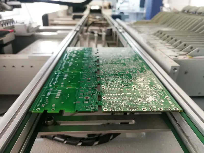
PCB Welding Production Line
The manufacturing processes for Industrial Welding Robot PCBs are critical to ensuring their performance and longevity in demanding industrial environments. These processes, from bare board fabrication to final assembly and inspection, must adhere to stringent quality control measures and industry standards to withstand the harsh conditions, including high temperatures, vibrations, and electromagnetic interference, inherent in welding operations. A robust manufacturing approach guarantees the reliability and precision essential for advanced robotic systems.
Process Stage
Key Activities
Critical Considerations
PCB Fabrication
Material cutting, drilling, etching, plating, solder mask application, surface finish
Defect detection, adherence to IPC standards (e.g., IPC-A-610 Class 2/3), reliability testing
Adherence to IPC standards, particularly IPC-A-610 Class 2 or 3 for high-reliability electronics, is paramount throughout these manufacturing stages. These standards provide comprehensive guidelines for acceptable quality, ensuring that the assembled PCBs meet the rigorous demands of industrial welding applications. Certification to these standards demonstrates a commitment to excellence and significantly reduces the risk of field failures.
IPC Standards Relevance IPC (Association Connecting Electronics Industries) standards are globally recognized benchmarks for electronic manufacturing. For welding robot PCBs, IPC-A-610 (Acceptability of Electronic Assemblies) Class 2 (dedicated service electronic products) or Class 3 (high-performance/harsh environment electronic products) are typically required. These classifications dictate the criteria for solder joint quality, component placement, cleanliness, and other critical aspects, directly impacting the PCB's reliability in extreme conditions. Compliance ensures uniformity and reduces defects, vital for systems where downtime is costly.
Testing and Validation: Guaranteeing Performance and Longevity
The rigorous testing and validation of Printed Circuit Boards (PCBs) for industrial welding robots are paramount to ensuring their unwavering performance, reliability, and extended longevity in demanding operational environments. Far beyond basic quality checks, a comprehensive testing regimen is crucial for identifying potential failure modes early, validating design integrity, and guaranteeing that the PCBs can withstand the extreme thermal, mechanical, and electrical stresses inherent in industrial welding applications. This meticulous validation process is what transforms a theoretically sound design into a robust, real-world solution capable of powering the precision and endurance required by modern robotic welding systems.
Why is functional testing critical for welding robot PCBs? Functional testing is essential for verifying that the PCB's circuitry operates as intended under simulated real-world conditions. For welding robot PCBs, this involves testing critical functions like motor control, sensor feedback, communication interfaces (e.g., EtherCAT, PROFINET), and power management. It ensures that every component and subsystem on the PCB performs its designed task accurately, contributing to the robot's overall precision and operational safety during welding tasks.
What environmental tests are crucial for industrial welding robot PCBs? Industrial welding environments are harsh, necessitating stringent environmental testing. Key tests include thermal cycling (simulating rapid temperature changes), humidity testing (to assess resistance to moisture), vibration testing (replicating operational vibrations), and shock testing (mimicking sudden impacts). These tests ensure the PCB's integrity and functionality are maintained even under extreme conditions, preventing failures due to environmental stressors common in welding applications.
How does accelerated life testing (ALT) contribute to PCB longevity for welding robots? Accelerated Life Testing (ALT) is vital for predicting the long-term reliability and lifespan of welding robot PCBs by subjecting them to intensified stress conditions (e.g., elevated temperatures, voltages, or cycles) over a shorter period. This methodology allows engineers to quickly identify potential wear-out mechanisms or latent defects that might only surface after extensive operation, enabling design improvements and material selections that significantly enhance the PCB's durability and reduce field failures over its intended service life.
What are common failure modes in welding robot PCBs that testing aims to identify? Testing aims to identify failure modes such as solder joint fatigue due to thermal cycling or vibration, delamination of PCB layers, component failures (e.g., capacitors, ICs), signal integrity issues from electromagnetic interference (EMI), and power delivery network inconsistencies. Early detection through comprehensive testing allows for design modifications, material changes, or process adjustments to mitigate these risks, ensuring the PCB's robustness in harsh industrial welding environments.
What is the role of IPC standards in the testing and validation of industrial welding robot PCBs? IPC standards, particularly IPC-A-610 for electronic assemblies and IPC-TM-650 for test methods, provide a universally recognized framework for quality and reliability. Adhering to these standards during testing and validation for welding robot PCBs ensures consistent quality, performance, and manufacturability. It establishes clear criteria for acceptable workmanship, test procedures, and performance benchmarks, which are critical for the high-reliability demands of industrial robotics.
Advanced PCB Technologies for Welding Robots
Advanced PCB Technology
To truly optimize the performance and capabilities of industrial welding robots, integrating advanced PCB technologies is essential. These innovations move beyond conventional designs, enabling greater functionality, reliability, and miniaturization, which are critical for the demanding and precise operations of modern robotic welding systems. Leveraging these cutting-edge PCB solutions allows for enhanced signal processing, power delivery, and sensor integration, directly contributing to superior weld quality, increased operational efficiency, and reduced maintenance.
High-Density Interconnect (HDI) PCBs HDI PCBs are crucial for complex welding robot control systems, allowing for a higher component density and more compact design. By utilizing microvias, blind vias, and buried vias, HDI technology facilitates more intricate routing and reduces signal path lengths, minimizing electromagnetic interference (EMI) and improving signal integrity. This enables the integration of advanced processors, memory, and high-speed communication interfaces within a smaller footprint, vital for sophisticated real-time control and data processing in welding applications. The enhanced routing capabilities also support a greater number of I/O pins for sensors and actuators, providing more granular control over the welding process. Zero One Solution Limited specializes in multi-layer HDI PCB manufacturing, ensuring the precision required for these advanced applications.
Flexible and Rigid-Flex PCBs Flexible and Rigid-Flex PCBs offer unparalleled advantages in welding robots where space is constrained and dynamic movement is inherent. Flexible PCBs can bend and conform to various shapes, eliminating the need for bulky cables and connectors, which reduces weight and improves reliability in articulated robot arms. Rigid-Flex PCBs combine the rigidity of standard PCBs with the flexibility of flex circuits, providing robust areas for component mounting while allowing for flexible interconnections. This hybrid approach is ideal for complex robotic joints and end-effectors, where components need stable support but also require dynamic connectivity. This technology significantly enhances durability by reducing stress on solder joints from constant motion, a common failure point in traditional rigid board setups.
Zero One Solution Limited: Your Partner for Welding Robot PCB Solutions
Welding Robot PCB Solution
In the demanding realm of industrial welding, where precision, durability, and uninterrupted operation are paramount, the underlying Printed Circuit Boards (PCBs) are the unsung heroes. Zero One Solution Limited stands at the forefront as a leading PCB solution provider, specializing in robust and high-performance PCBs specifically engineered for industrial welding robots. Our comprehensive expertise, spanning rapid prototyping to manufacturing and assembly, ensures that your welding robots achieve optimal performance, superior reliability, and extended operational longevity.
Rapid Prototyping Excellence We accelerate your product development cycle with our rapid-response R&D prototype manufacturing, enabling quick iteration and validation of designs for welding robot PCBs. Our streamlined processes ensure that innovative solutions are brought to market with exceptional efficiency, reducing time-to-market and fostering technological advancements in your welding operations. This agile approach is critical for staying competitive in a fast-evolving industrial landscape, allowing for rapid deployment of new welding robot capabilities and improvements.
The Future of PCBs in Industrial Welding Robots
Future Welding Robot PCBs
The relentless march of industrial automation, spearheaded by sophisticated welding robots, is inextricably linked to advancements in Printed Circuit Board (PCB) technology. As welding robots become more intelligent, compact, and interconnected, the PCBs at their core must evolve to meet these demands. This evolution is driven by several key trends that promise to redefine the capabilities and operational paradigms of future industrial welding systems.
Miniaturization and High-Density Integration Future welding robots will demand even smaller, lighter, and more powerful PCBs. This trend is fueled by the need for increased agility, reduced footprint, and improved energy efficiency. High-Density Interconnect (HDI) technology, already crucial, will further evolve with microvias and finer lines, enabling more components to be packed into smaller areas. This not only saves space but also reduces signal path lengths, leading to faster processing and lower power consumption. Expect to see widespread adoption of System-in-Package (SiP) and Package-on-Package (PoP) solutions, integrating multiple chips and passive components directly onto or within the PCB substrate, further reducing overall size and weight while boosting functionality.
Wireless Communication for Enhanced Flexibility The integration of advanced wireless communication capabilities directly onto PCBs will revolutionize how welding robots are controlled, monitored, and maintained. Technologies such as 5G, Wi-Fi 6E, and even emerging ultra-wideband (UWB) will enable seamless data exchange between robots, central control systems, and other factory equipment. This will facilitate real-time performance monitoring, remote diagnostics, and over-the-air software updates, significantly reducing downtime and increasing operational flexibility. The move towards wireless will also simplify wiring harnesses, further contributing to robot agility and reliability by reducing potential points of failure.
Artificial Intelligence (AI) Integration at the Edge The future of industrial welding robots will see AI capabilities moving from centralized servers to the edge – directly onto the robot's PCB. This involves embedding specialized AI accelerators and neural processing units (NPUs) on the board itself. Edge AI will enable robots to perform real-time data analysis, make autonomous decisions, and adapt to changing welding conditions with unprecedented speed and accuracy. Applications include real-time defect detection, predictive maintenance based on sensor data, and dynamic path planning. This localized processing reduces latency and bandwidth requirements, making robots more responsive and intelligent even in offline or intermittently connected environments. Such integration paves the way for truly self-optimizing welding processes.
FAQs about Industrial Welding Robot PCBs
Understanding the intricacies of Printed Circuit Boards (PCBs) in industrial welding robots is crucial for optimizing performance, reliability, and longevity in demanding manufacturing environments. This section addresses common inquiries, providing essential insights into the design, manufacturing, testing, and maintenance of these critical components.
Why are specialized PCBs essential for industrial welding robots? Specialized PCBs are essential for industrial welding robots due to the extreme operating conditions they encounter, including high temperatures, significant vibrations, electromagnetic interference, and corrosive atmospheres. Unlike general-purpose PCBs, those designed for welding robots incorporate robust materials, advanced thermal management solutions, enhanced signal integrity features, and durable coatings to ensure stable and reliable operation, prevent premature failure, and maintain precise control over complex welding processes.
What are the most critical design considerations for Industrial Welding Robot PCBs? The most critical design considerations for industrial welding robot PCBs include robust thermal management to dissipate heat generated by power components, high vibration resistance through secure component mounting and optimized board layout, stringent signal integrity for precise data transmission, and a compact form factor to fit within confined robot structures. Material selection (e.g., high-Tg laminates, metal core PCBs) is also paramount to withstand harsh environments and ensure long-term reliability.
How do manufacturers ensure the reliability of PCBs used in welding robots? Manufacturers ensure the reliability of PCBs for welding robots through rigorous processes. This includes utilizing high-quality, industrial-grade materials, employing advanced manufacturing techniques (e.g., precise etching, optimized soldering profiles), implementing comprehensive quality control measures at every stage, and performing extensive testing. Such testing includes functional validation, environmental stress screening (thermal cycling, humidity), vibration testing, and accelerated life testing to simulate operational wear and identify potential failure points before deployment.
What advanced PCB technologies are enhancing welding robot capabilities? Advanced PCB technologies enhancing welding robot capabilities include High-Density Interconnect (HDI) PCBs for miniaturization and improved signal routing, flexible and rigid-flex PCBs for compact, dynamic applications, and embedded components (e.g., resistors, capacitors) for reduced board size and improved performance. These innovations contribute to more compact, agile, and intelligent welding robots with enhanced precision and expanded functionality.
What are the best practices for maintaining and extending the lifespan of Industrial Welding Robot PCBs? Best practices for maintaining and extending the lifespan of industrial welding robot PCBs include regular environmental control to manage temperature and humidity, routine visual inspections for signs of wear or damage, proper cleaning procedures to remove dust and contaminants, and ensuring stable power supply to prevent electrical stress. Furthermore, preventative maintenance, such as checking component connections and updating firmware, can significantly enhance operational longevity and prevent unexpected downtime.
In conclusion, the PCB is a critical component of industrial welding robots, impacting their precision, reliability, and overall performance. Zero One Solution Limited provides comprehensive PCB solutions tailored to the specific needs of the welding robot industry. By focusing on innovative design, rigorous testing, and high-quality manufacturing, we ensure that our PCBs meet the demanding requirements of this sector.
We invite you to explore how our PCB solutions can enhance the performance and reliability of your industrial welding robots. Contact us today to discuss your project requirements and discover how Zero One Solution Limited can help you achieve your automation goals. Let Zero One Solution Limited be your trusted partner in PCB solutions, driving innovation and excellence in industrial automation.