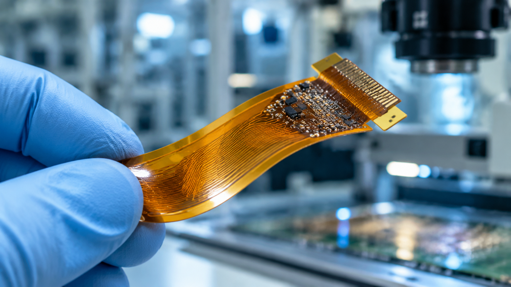
Introduction: FPC (Flexible Printed Circuit) boards enable 3D routing, weight reduction, and space savings in devices like smartphones, wearables, and medical equipment. This guide covers FPC materials (PI, copper foil, coverlay, stiffeners), common structures (single-sided, double-sided, multilayer, rigid-flex), advantages and limitations, and the critical bend radius calculation that prevents copper fatigue and delamination.
Description: Based on AnyPCBA's small-to-medium volume FPC and PCB manufacturing experience, this guide explains FPC structure, materials, types, advantages, and bend radius calculation—and how DFM review catches bend radius, stiffener, and stack-up issues before production.
As modern electronics—such as smartphones and wearables—become thinner and smaller, traditional rigid PCBs can no longer meet the demands of 3D assembly.
This is where FPC (Flexible Printed Circuit) comes in. By forming conductive patterns on a flexible substrate through photo-imaging and etching, FPCs enable circuits to bend, fold, and flex, freeing electronics from the constraints of flat boards.
This article explains FPC materials, structures, advantages, limitations, and the critical formula for calculating bend radius.
An FPC looks like a thin plastic film, but it contains high-precision manufacturing. A typical FPC consists of four core materials:
The base material is the FPC skeleton, typically made of copper foil and polyimide (PI). Based on whether an adhesive layer is present, there are two types:
Adhesive-based (3-layer): copper foil, adhesive, and PI. Lower cost but thicker and less flexible.
Adhesive-free (2-layer): only copper foil and PI. Now widely used due to its thinner profile, better dimensional stability, and superior heat and flex resistance.
The cover film is the equivalent of a rigid board's solder mask. It consists of release paper, adhesive, and PI. During lamination, the release paper is removed, leaving only the adhesive and PI to insulate and protect the traces.
FPCs are too flexible to withstand component placement and connector insertion stress. A stiffener is bonded to specific areas (e.g., behind connectors or under SMD components) to add mechanical strength. Common stiffener materials include:
FR4: Same as rigid board material; cost-effective.
Stainless steel: Extreme hardness, suitable for high-frequency insertion or high-strength support.
PI: Same as coverlay, used for ultra-thin or high-temperature support (2–9 mil thickness).
Includes pure adhesive (for multilayer FPC or rigid-flex bonding), EMI shielding film, and pure copper foil (for open-window boards).
Based on layer count and structure, FPCs fall into these common types:
Single-sided (Type 1): one conductive layer, coverlay on one side.
Double-sided (Type 2): two conductive layers connected through plated through-holes (PTH).
Multilayer (Type 3): three or more conductive layers interconnected through vias. (Note: AnyPCBA currently supports multilayer FPC fabrication up to 12 layers.)
Special structures: open-window boards, split-layer boards, and rigid-flex boards combining the advantages of rigid and flexible circuits.
Shorter assembly time: eliminates extra cable connections, improving integration.
Smaller size and weight: much thinner and lighter than rigid boards—ideal for portable devices.
True 3D assembly: can bend, fold, and flex freely, maximizing space utilization.
Lower overall cost: despite higher initial cost, high-volume production saves connector and wiring costs.
High one-time initial cost: artwork, photoplotting, and special processes are expensive—unsuitable for very small prototype runs.
Difficult to modify and repair: changes require reworking from artwork, and repairing coverlay is extremely difficult.
Size limitations: production equipment size constrains maximum board dimensions.
If the bend radius is poorly designed, the FPC can suffer copper cracking and delamination—fatal failure modes.
During bending, the inner curve is under compression and the outer curve under tension. Stress magnitude depends directly on FPC thickness and bend radius. Designers must calculate the minimum bend radius.
R = (c / 2) × [ (100 - Eb) / Eb ] - D
R = minimum bend radius (μm)
c = copper thickness (μm)
D = coverlay thickness (μm)
Eb = allowable copper elongation (%)
Rolled annealed copper: maximum ≤ 16%
Electro-deposited copper: maximum ≤ 11%
Flex-to-install (one-time bend): use the extreme limit (e.g., 16% for rolled copper).
Static bend after installation: per IPC-MF-150 minimum elongation (e.g., 10% for rolled copper).
Dynamic flex: elongation must be ≤ 0.3% (e.g., foldable phone hinges).
Magnetic head applications: elongation ≤ 0.1% (extremely demanding).
Rules of thumb: minimum bend radius is typically 3–6× conductor thickness for single-sided, 6–10× for double-sided, 10–15× for multilayer, and 20–40× for dynamic single-sided FPCs.
FPC fabrication is more precise than rigid PCB manufacturing. Typical single- and double-sided flows are:
Single-sided: material cutting → baking → dry film lamination → exposure → development → etching → stripping → coverlay lamination → curing → surface finish → electrical test → assembly → profile punching → final inspection → packaging.
Double-sided: adds drilling, black hole (or electroless copper), and VCP plating steps for interlayer connection.
As a small-to-medium volume manufacturer, AnyPCBA understands that FPC manufacturing hinges on extreme dimensional stability and flex endurance control.
Our manufacturing capabilities cover single-sided, double-sided, and up to 12-layer multilayer FPCs, plus rigid-flex boards. During DFM review, our engineers focus on:
Bend radius validation: confirming copper type (rolled vs. electro-deposited) and thickness meet dynamic/static flex requirements.
Stiffener design review: confirming stiffener material (FR4, steel, or PI) and placement protect the flexible substrate during SMT and connector insertion.
Stack-up evaluation: optimizing PI and adhesive symmetry in multilayer FPCs to prevent severe warpage during high-temperature lamination.
If you're developing ultra-thin consumer electronics, medical probes, or wearables requiring high-reliability FPC or rigid-flex prototyping and production, contact us through the AnyPCBA website.