Mastering Breadboard Circuits: A Comprehensive Guide for Beginners to Experts
2025.01.23
Imagine the intricate circuits within your smartphone, now picture building a similar system without soldering! That's the magic of a breadboard circuit – a tool that allows you to experiment and prototype electronics without the need for permanent connections. This article will be your guide, taking you from understanding the basics to creating more complex circuits with ease, bridging the gap between theory and hands-on experimentation using the versatile breadboard.
Understanding the Breadboard Structure
Breadboard Structure
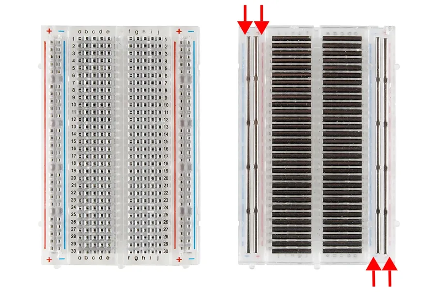
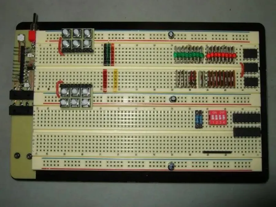
A breadboard, also known as a protoboard, is a solderless device used for prototyping and experimenting with electronic circuits. Its internal structure allows for temporary connections between components without the need for soldering, making it an indispensable tool for both beginners and experienced electronics enthusiasts. This section delves into the intricate details of a breadboard's layout, ensuring a thorough understanding of its functionality.
The typical breadboard features a grid of interconnected holes. These holes are arranged into distinct sections:
Power Rails These are typically located on the sides of the breadboard and are used to provide power to the circuit. They often run the entire length of the board and are usually marked with '+' and '-' symbols to indicate the positive and negative voltage rails. Note that the power rails may be split in the middle, especially on larger breadboards, so they must be jumpered together to ensure a continuous rail if necessary.
Terminal Strips These form the main working area of the breadboard, consisting of rows of connected holes. Each row of 5 holes is electrically connected. However, there is a vertical separation between the left and right sides. This gap is typically used to place integrated circuits (ICs) so that the pins on either side of the IC are on separate connection strips.
Distribution Strips Some breadboards may have additional distribution strips, which are typically used for distributing power or ground. These strips are horizontally connected and may be on the top or middle of the breadboard.
Key points to remember when using a breadboard:
Component Placement Components are placed into the holes, and connections are made by inserting wires into the same rows as component legs. Ensure that component leads are fully inserted for a reliable connection.
Avoiding Short Circuits Ensure that connecting wires are insulated and that bare wires do not come into contact with other conducting elements on the board. Avoid placing components or wires so that they could touch and cause a short circuit.
Wire Management Employ well-insulated, solid-core wires for reliable connections. Use wire strippers and appropriate wire lengths to keep the wiring neat and avoid tangling, this will also help with troubleshooting.
Breadboard Section
Description
Function
Power Rails
Longitudinal rows on the sides (or sometimes top/bottom) of the board. Typically marked with '+' and '-' symbols.
Provide power and ground connections to the circuit.
Terminal Strips
Groups of 5 holes interconnected horizontally, separated by a central dividing channel.
Used to connect electronic components; the central dividing channel accommodates ICs.
Distribution Strips
Horizontally connected rows; may be for distributing power or ground.
Distribute power or ground efficiently; optional feature on some boards.
Essential Components for Breadboard Circuits
Breadboard Components
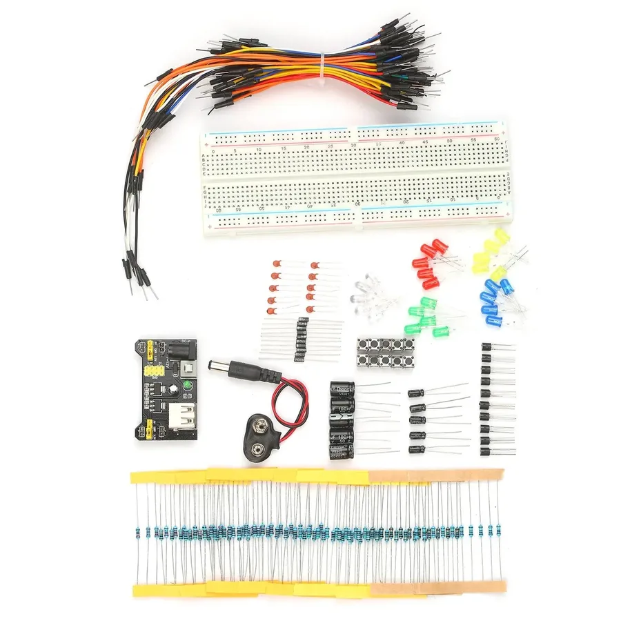
Building circuits on a breadboard requires a variety of electronic components, each serving a specific function. This section introduces the fundamental components such as resistors, capacitors, LEDs, transistors, and integrated circuits (ICs), and discusses their roles and proper placement on the breadboard, which is vital for successful circuit prototyping.
Component
Function
Breadboard Placement Considerations
Resistors
Limit current flow, provide voltage division.
Can be placed horizontally or vertically, but avoid shorting rows. Color code indicates resistance value.
Capacitors
Store electrical energy, filter signals.
Electrolytic capacitors are polarized and must be placed correctly according to polarity markings. Ceramic capacitors are non-polarized.
LEDs (Light Emitting Diodes)
Emit light when current flows.
Polarized; longer lead (anode) connects to positive side, shorter lead (cathode) to negative. Always use a current-limiting resistor in series.
Transistors (BJTs, MOSFETs)
Amplify or switch electronic signals and power.
Typically have three leads (base/gate, collector/drain, emitter/source). Connect to appropriate rows based on their pin configurations and circuit requirements.
Integrated Circuits (ICs)
Perform complex functions.
Carefully align pins with breadboard rows. Often have specific pinouts that must be followed. Use IC holders for multiple reuse.
Setting Up Your First Simple Breadboard Circuit
Simple Breadboard LED Circuit
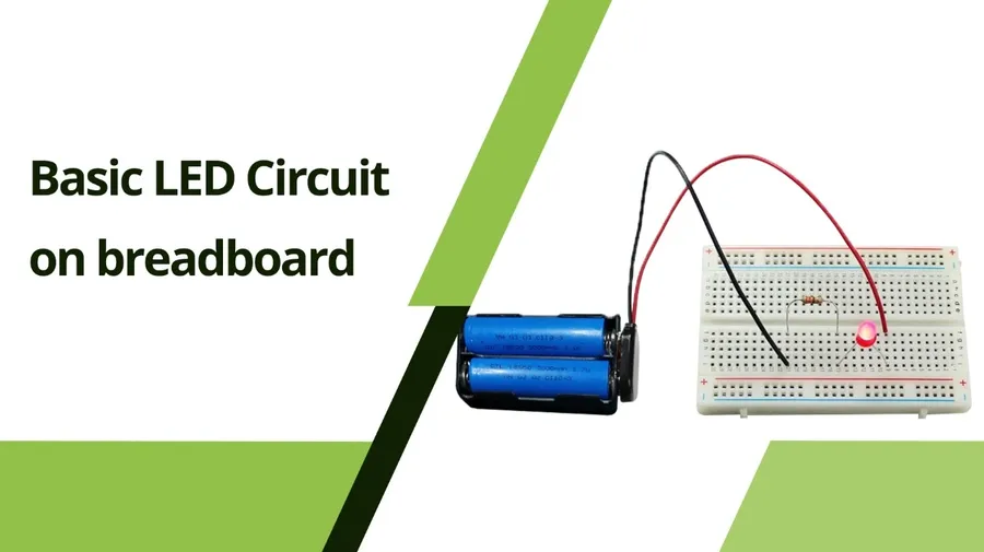
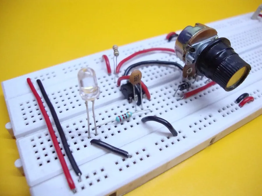
Creating a basic circuit on a breadboard is a fundamental skill for electronics enthusiasts. This section provides a step-by-step guide to building a simple LED circuit, covering necessary components, connections, and power considerations to get you started with hands-on electronics prototyping.
Required Components To build a simple LED circuit, you'll need a breadboard, an LED (Light Emitting Diode), a resistor (typically between 220Ω and 1kΩ, adjust based on your LED's specification), some jumper wires and a power source (e.g., a 9V battery with a battery clip, or a 5V USB power supply).
Component Placement Place the LED on the breadboard, ensuring that its longer lead (anode, positive terminal) and the shorter lead (cathode, negative terminal) are inserted into different terminal strips. Insert the resistor in series with the LED, connecting it to either the anode or cathode leg of the LED. Ensure the resistor connects to a separate row on the breadboard.
Making Connections Connect the positive terminal of your power source to a row that is connected to the resistor's leg that is not connected to the LED. Connect the negative terminal of your power source to the same row as the LED's cathode (the shorter lead). This completes the circuit.
Power Source Selection The appropriate voltage and current required depends on the specific components. For an LED, it's crucial to limit current with a resistor to prevent damage. Typically, LEDs have a forward voltage drop, and a resistor is used to drop the excess voltage. For example, if your LED has a forward voltage of 2V, and you have a 5V supply, then a resistor of (5 - 2)/0.020 = 150 Ohms (assuming 20 mA current) will give you the right current. A 220 Ohm to 1k Ohm resistor is a reasonable starting point for a typical LED with a 5V supply. If using a 9V battery, you need to increase the resistance of the resistor appropriately.
Testing the circuit Carefully apply the power and check if the LED illuminates. If it does not, double-check all connections, resistor value, LED polarity and power supply.
Component
Function
Considerations
Breadboard
Provides a solderless platform for prototyping
Ensure it's clean and in good condition
LED
Emits light when current flows through it
Observe correct polarity (anode and cathode), current limits, forward voltage
Resistor
Limits current flowing through the LED to prevent damage
Select a resistor value that is suitable for your power source and LED, typically in the 220 Ohm to 1k Ohm Range for a 5V Supply.
Jumper Wires
Connect components on the breadboard
Use solid core wires. Ensure secure connections.
Power Source
Supplies the energy for the circuit
Choose appropriate voltage and current based on component ratings, ensure consistent stable supply
Advanced Breadboard Techniques: Troubleshooting and Optimization
Troubleshooting a Breadboard Circuit
Efficient and reliable breadboard circuits require not only a solid understanding of the fundamentals, but also the ability to troubleshoot effectively and optimize the layout. This section delves into common issues, diagnostic techniques, and best practices for organization and wire management, enabling the construction of more robust prototypes.
Common Breadboard Circuit Issues Frequent problems include loose connections, incorrect component placement, shorts due to stray wires, and faulty components. Understanding these issues is crucial for efficient troubleshooting.
Diagnosing Connectivity Problems Use a multimeter to check continuity between connection points, especially when dealing with complex circuits. This method helps pinpoint breaks or shorts in the circuit pathways. Always double-check the voltage between the power rails and ensure correct polarity when using polarized components.
Component Malfunctions Test individual components like resistors and LEDs before inserting them into the circuit. Replacing faulty components early can save significant time and effort during prototyping.
Power Supply Issues Verify the stability of the power supply to ensure it delivers the required voltage and current. Fluctuations or inadequate power can cause erratic behavior in the circuit. Always double-check the polarity.
Effective organization and wire management are essential for building reliable and easy to debug breadboard circuits. A well-organized setup is easier to troubleshoot and modify.
Optimizing Layout Plan the component placement logically to minimize long wire runs and overlaps. Using a logical layout mirroring the circuit diagram helps to avoid wiring errors and simplifies debugging.
Wire Management Use solid-core wires of different colors to avoid confusion, and trim wires to the appropriate length to keep the breadboard neat and prevent shorts. Group wires logically and avoid excessive crossing.
Use Jumpers with Connectors Using breadboard jumper cables with connectors to keep wiring organized and reliable and minimize loose connections that could cause intermittent problems.
Labeling Label the critical components and connections for easy identification, especially when building complex circuits. Labels can reduce troubleshooting time significantly.
Issue
Diagnosis Method
Solution
Loose Connections
Check continuity with a multimeter
Firmly press components and wires into the breadboard
Component Shorts
Visual inspection and continuity test
Adjust component placement and rewire if necessary
Faulty Components
Test each component individually
Replace with a known working component
Inconsistent Power
Check the power source with a multimeter
Ensure the power source can deliver adequate current and voltage
Powering Your Breadboard: Different Options and Considerations
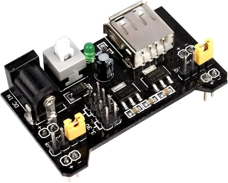
Breadboard Power Supply
Providing the correct power to a breadboard circuit is paramount for its proper operation and the safety of its components. The choice of power supply depends on the circuit's voltage and current requirements, as well as the user's accessibility to different power sources.
Here are some common power supply options, each with its own characteristics:
Batteries Batteries are portable, providing an isolated power source. Common options include 9V batteries, AA or AAA batteries (often used in battery packs), and coin cells. It is essential to verify the voltage and current capabilities of the battery, and to calculate if it is appropriate for your circuit. Multiple batteries can be used in series to achieve higher voltages, or in parallel for higher current capacity.
USB Adapters USB power adapters are ubiquitous, readily available, and typically provide a 5V DC output with varying current capabilities. These are a great choice for lower voltage circuits that are not too power demanding. USB ports on computers can also be used, but the current output might be lower, so it's best to use the adapter when possible. Remember that many USB ports are current limited.
Dedicated Benchtop Power Supplies Benchtop power supplies are laboratory grade power sources that often offer variable voltage and current settings, allowing for precise control over the supply parameters and often have current limiting capabilities, which are useful to prevent damage to components during troubleshooting. They also tend to be larger and more expensive than other options, which makes them more suited for permanent installations, labs and more advanced work.
Key considerations when selecting a power supply include:
Voltage Requirements The voltage provided should match the requirements of your circuit. Mismatched voltages can damage components. Check datasheets of components to make sure the voltage is adequate.
Current Requirements The power supply must provide sufficient current for your circuit. Too little current can cause circuit to malfunction. Check datasheets of components to make sure the power source is able to supply adequate current.
Polarity Ensure the polarity is correct when connecting the power source. Reversed polarity can cause damage to components. Double-check the positive and negative leads before connecting the circuit.
Stability A stable power supply without excessive voltage or current fluctuations will ensure consistent performance and may be required for certain circuits.
Power Supply Type
Typical Voltage
Typical Current
Pros
Cons
9V Battery
9V DC
Up to 500mA (depending on battery type)
Portable, readily available
Limited capacity, may require a clip, relatively high internal resistance, voltage drops as battery discharges
AA/AAA Batteries (in packs)
1.5V DC per cell
Up to 1A (depending on battery type and number of cells)
Portable, convenient for low-power applications
Lower voltage per cell, requires a battery holder or pack
Coin Cell Battery
3V DC
1-20 mA
Very small and compact
Very low current, limited use for high-power circuit
USB Adapter
5V DC
0.5A to 3A (depending on adapter)
Widely available, convenient, low cost
Fixed voltage, current limited by the adapter
Benchtop Power Supply
Variable, typically 0-30V DC
Variable, typically 0-5A
Precise control, voltage, and current limiting
Expensive, less portable
Frequently Asked Questions about Breadboard Circuits
This section addresses common questions about breadboard circuits, offering concise and insightful answers to help users understand and effectively use this prototyping tool.
What exactly is a breadboard circuit? A breadboard circuit is a solderless prototyping tool used to build and test electronic circuits. It features interconnected rows and columns of holes that allow components to be easily connected without soldering. This enables quick and flexible circuit design and modifications.
Are breadboards suitable for beginners in electronics? Yes, breadboards are excellent for beginners. Their solderless nature makes them safe and easy to use, allowing novices to quickly experiment with different electronic components and circuit configurations. The visual and tangible connection system facilitates hands-on learning of basic circuit concepts.
How do I effectively use a breadboard for a beginner project? Start by understanding the internal connections: power rails run along the sides and terminal strips run horizontally. Place components across the central gap to avoid shorts. Use jumper wires to connect components and power sources. Begin with simple circuits, like an LED with a resistor. Verify connections before applying power and ensure the correct polarity for polarized components.
What is the key difference between a breadboard and a printed circuit board (PCB)? A breadboard is a temporary, solderless prototyping platform, allowing for rapid changes and experimentation. A PCB is a permanent board with conductive tracks to connect components via soldering. Breadboards are ideal for early-stage testing and design iteration, while PCBs are used for mass production and permanent applications.
Can I use breadboards for high frequency circuits? Breadboards are generally unsuitable for high frequency circuits, due to their inherent parasitic capacitance and inductance. The long wire lengths and non-ideal connections cause signal degradation. It’s better to use a PCB or other prototyping methods optimized for high frequency applications.
Are there any limitations to using a breadboard for more complex circuits? Yes, breadboards can become cumbersome for complex circuits. The wire clutter, potential for loose connections, and physical space limitations may make it difficult to manage larger and more complex systems. In such instances, PCBs may be more appropriate.
How long can I expect a circuit to last when using a breadboard? Breadboard circuits are temporary and not designed for long term or high stress applications. Components can loosen over time, and the connections are not as robust as soldered joints. For permanent solutions, transfer the circuit to a PCB. However, circuits on breadboards can be used for a considerable period with careful use and storage.
Breadboard Circuit vs. PCB: Understanding the Differences
Breadboard vs PCB
Breadboards and Printed Circuit Boards (PCBs) are both fundamental tools in electronics, but they serve distinct purposes with different advantages and limitations. Breadboards are primarily used for prototyping and experimenting with circuits, while PCBs are designed for creating permanent, robust electronic devices.
Feature
Breadboard Circuit
Printed Circuit Board (PCB)
Purpose
Prototyping, experimentation, temporary circuits
Final product, permanent circuits, mass production
Construction
Solderless, reusable, uses interconnected strips
Soldered components on conductive traces, single use
Flexibility
Highly flexible, easy to change components and connections
Less flexible, difficult to modify after fabrication
Durability
Fragile, not suitable for harsh environments
Robust, suitable for various operating conditions
Complexity
Suitable for simple to moderately complex circuits
Can handle very complex and dense circuitry
Cost
Low cost, reusable components
High initial cost, economical for mass production
Size and Space
Bulky, more space required, limited space for components
Compact, allows high density integration
Assembly Time
Fast to assemble, plug and play
Long assembly time, requires soldering and fabrication
Signal Integrity
Prone to noise and signal loss, not good for high speed
Excellent signal integrity, suitable for high-speed applications
Consumer electronics, industrial equipment, embedded systems
Project Ideas for Breadboard Circuit Enthusiasts
Breadboard Project
Breadboards are excellent platforms for prototyping various electronic circuits, from simple LED circuits to more complex microcontroller-based systems. This section presents several project ideas to inspire your experimentation, providing a range of complexity to suit different skill levels.
Simple LED Circuit A fundamental project involving an LED, a resistor, and a power source. This teaches basic circuit assembly and current limiting using resistors. Required components include: LED, 220-ohm resistor, breadboard, hook-up wires, and a power supply (e.g., 3V battery).
Basic Transistor Switch Use a transistor to control an LED, demonstrating how a small current can control a larger one. This introduces transistor functionality. Required components include: NPN transistor (e.g., 2N2222), 1k-ohm resistor, LED, 220-ohm resistor, breadboard, hook-up wires, and a power supply.
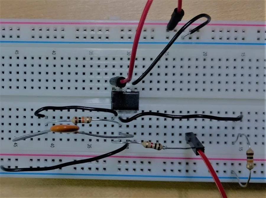
555 Timer Astable Multivibrator A project that utilizes the versatile 555 timer IC to create a blinking LED or generate a square wave. It allows experimenting with timing circuits. Required components include: 555 timer IC, resistors, capacitors, LED, breadboard, hook-up wires, and a power supply.
Light-Activated LED Build a circuit where an LED turns on when a light-dependent resistor (LDR) detects darkness, demonstrating sensor integration. Required components include: LDR, potentiometer, transistor, LED, resistors, breadboard, hook-up wires, and a power supply.
Basic Op-Amp Comparator Implement a basic op-amp comparator circuit, which compares two voltages and produces a digital output, an introduction to analog circuits. Required components include: op-amp (e.g., LM741), resistors, breadboard, hook-up wires, and a power supply.
Arduino-Based Blinking LED Combine an Arduino microcontroller with a breadboard to create a blinking LED using programmable control. This introduces microcontroller-based prototyping. Required components include: Arduino board, LED, 220-ohm resistor, breadboard, hook-up wires, and a USB cable.
Temperature Sensor with Arduino Use a temperature sensor (e.g., TMP36) with an Arduino to measure and display temperature readings, showcasing data acquisition. Required components include: Arduino board, TMP36 temperature sensor, breadboard, hook-up wires, and a USB cable.
Breadboard Circuit Safety Tips and Best Practices
Ensuring safety when working with breadboard circuits is paramount to prevent injury and damage to components. Proper handling of electronics, power supplies, and organized setups are crucial for a safe and efficient prototyping environment. Adhering to safety guidelines and best practices protects both the user and the equipment.
Component Handling Always handle electronic components with care. Avoid bending leads excessively or forcing components into the breadboard. Use antistatic mats and wrist straps when working with sensitive components like ICs to prevent damage from electrostatic discharge (ESD).
Power Supply Precautions Double-check the voltage and current ratings of your power supply and components before powering up. Ensure the correct polarity is used (positive and negative terminals correctly connected). Never connect a power supply to a circuit without a current-limiting resistor, especially when dealing with LEDs, to avoid damage.
Wire Management Use solid-core hookup wire of the correct gauge (typically 22 or 24 AWG). Keep wires short and neatly organized to avoid accidental shorts and to make the circuit easier to troubleshoot. Use color-coded wires to differentiate between power, ground, and signal paths.
Short Circuit Awareness Be extremely cautious to avoid short circuits. Ensure that no exposed metal parts are touching each other. Short circuits can cause components to overheat, potentially leading to damage or fire. When powering up a new circuit, start with a low voltage and slowly increase it, testing each step.
Working Environment Ensure your workspace is well-lit and free from clutter. Avoid working near liquids or in damp environments. Use proper tools such as wire strippers and cutters, and use them correctly. Always unplug the power supply before making changes to the circuit.
Storage of Components Store components in ESD-safe containers or bags. Organize components in a way that makes them easy to find and use. Avoid storing components in direct sunlight or in humid environments, which can degrade their performance or cause corrosion.
Component Datasheets Always refer to the datasheet of each component for its specifications and limitations. Understand the pinout of each IC before connecting it to avoid damaging the component. These documents provide important guidance regarding the component's functionality and limitations.
From the humble beginnings of using a breadboard circuit for simple LEDs to sophisticated sensor systems, your journey into electronics is wide open. With a solid understanding of breadboard layouts, components, and best practices, you can prototype nearly any electronic circuit. Remember that the breadboard is your tool for experimentation. As you continue to learn, you'll not only understand circuit operation but also the elegance of electronic design, all thanks to the versatile breadboard.