In our increasingly interconnected world, electromagnetic interference (EMI) can disrupt everything from our smartphones to critical industrial equipment. Common mode chokes, though often unseen, play a vital role in maintaining signal integrity by filtering out unwanted noise. This article will demystify the common mode choke, explaining its working principle, practical applications, and key parameters, to provide you with a comprehensive understanding of how they keep our tech humming along smoothly.
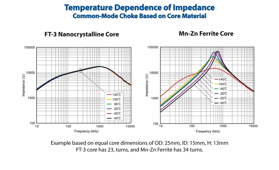
Common mode chokes are passive electronic components, functioning as electrical filters, specifically designed to suppress high-frequency common-mode noise in electronic circuits. They achieve this by presenting a high impedance to common-mode currents while allowing differential-mode signals to pass with minimal attenuation.
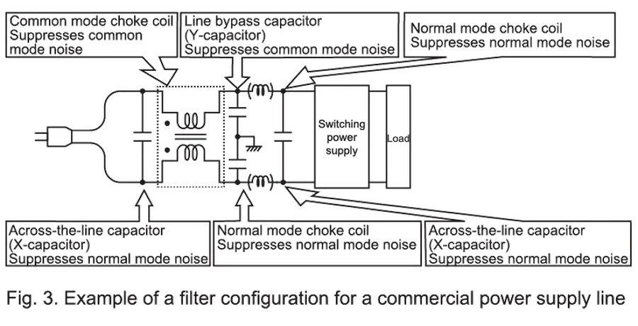
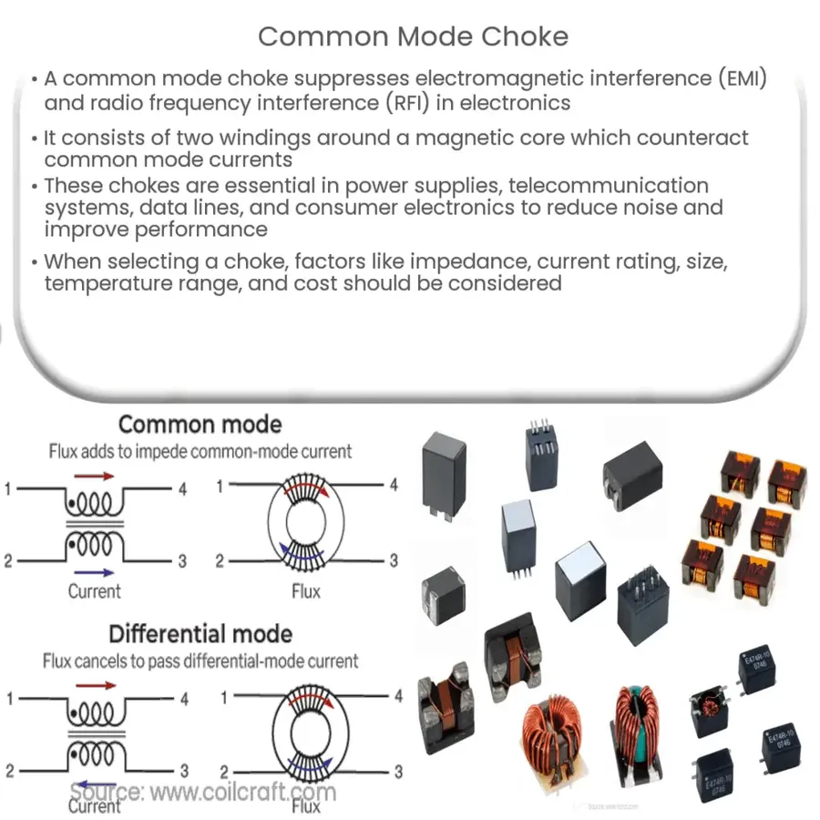
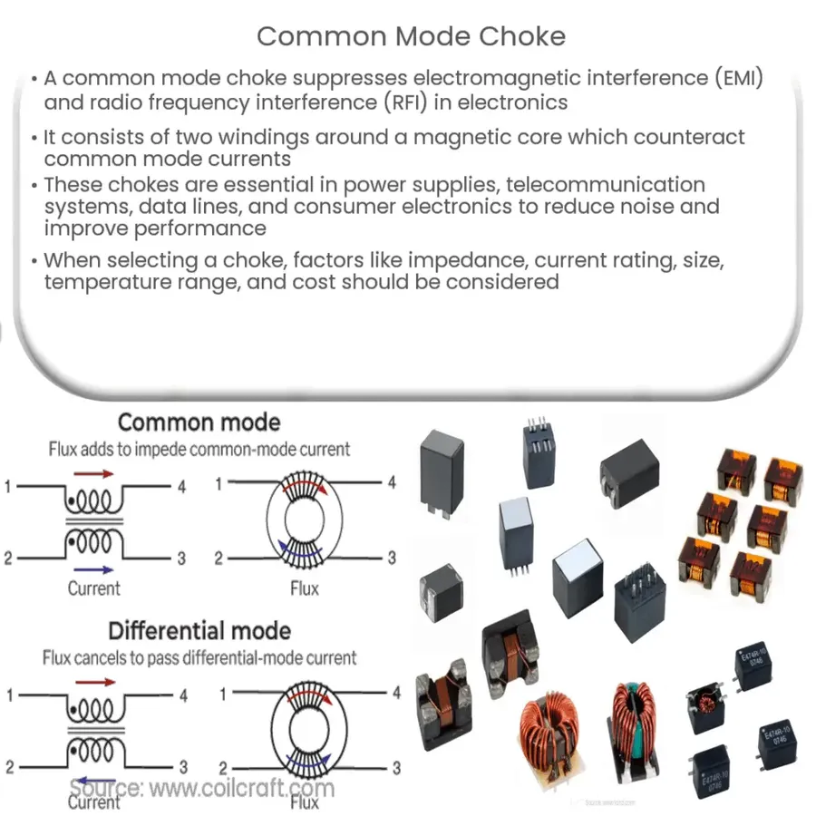
Common mode chokes operate on the principle of magnetic flux cancellation to suppress common mode noise while allowing differential signals to pass unimpeded. This is achieved through their unique winding configuration, which induces opposing magnetic fields for common mode currents, leading to high impedance, effectively blocking them. Conversely, differential currents create aiding magnetic fields, resulting in low impedance, and allowing them to pass through with minimal attenuation.
The core component of a common mode choke is a magnetic core, typically made of ferrite material, around which two or more wires are wound. These windings are key to understanding the mechanism.
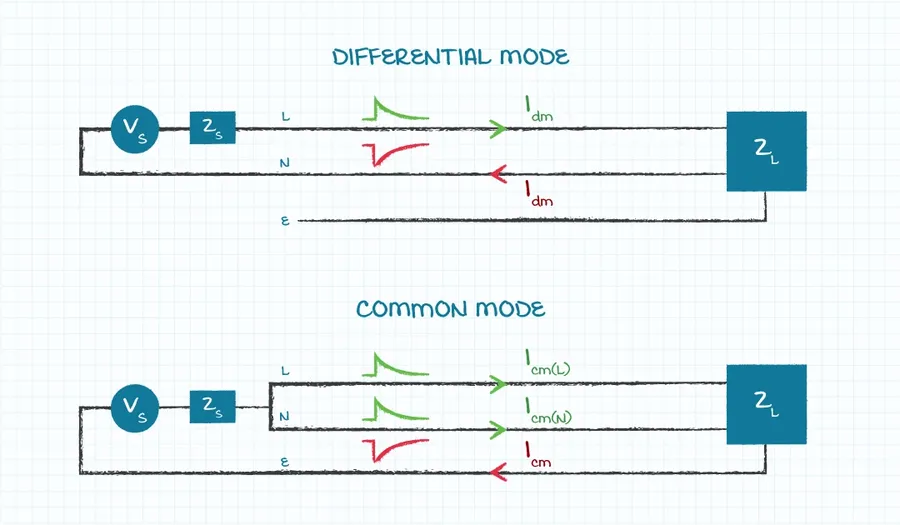
Understanding the distinction between common mode and differential mode noise is crucial for effective noise mitigation, particularly when employing common mode chokes. These two types of noise manifest differently in electrical circuits and require different filtering approaches. Common mode noise, often the more challenging to suppress, appears on both signal lines simultaneously, while differential mode noise appears as a signal difference between two lines. Common mode chokes are specifically designed to target and attenuate common mode noise, leaving the desired differential signal relatively unaffected.
| Characteristic | Common Mode Noise | Differential Mode Noise |
|---|---|---|
| Signal Appearance | Appears identically on both lines relative to ground. | Appears as a difference in signal between two lines. |
| Current Direction | Current flows in the same direction on both lines. | Current flows in opposite directions on the two lines. |
| Source | Often due to ground loops, capacitive coupling, and external electromagnetic interference. | Generally originates from the signal source itself or load impedance imbalance. |
| Filtering | Effectively attenuated by common mode chokes. | Effectively attenuated by differential mode filters (e.g., capacitors). |
| Impact | Can disrupt system operation and cause electromagnetic compatibility (EMC) issues. | Can degrade signal quality and system performance. |
The fundamental reason common mode chokes are effective against common mode noise lies in their construction. When common mode noise current flows through the choke, the magnetic fluxes generated in the core add together. This additive flux creates a significant impedance to the flow of common mode current, thus attenuating it. Conversely, the magnetic flux generated by differential mode current cancels out within the core. Therefore the choke offers minimal impedance to differential mode signals. This behavior enables the choke to selectively filter out unwanted common mode noise while allowing the desired differential signal to pass relatively unaffected. This differentiation makes them an invaluable component in signal and power integrity applications.
Understanding the key parameters of common mode chokes is crucial for effective noise filtering. These parameters dictate how well a choke performs in attenuating common-mode noise and include impedance, inductance, current rating, and DC resistance. Proper selection based on these parameters ensures optimal system performance and avoids potential issues.
| Parameter | Description | Implications for System Performance |
|---|---|---|
| Impedance | The total opposition to current flow at a specific frequency, measured in ohms. It is a combination of resistance and reactance. | Higher impedance at the noise frequency results in greater attenuation of common-mode noise. The impedance must be appropriate for the frequency range to be filtered. |
| Inductance | The measure of a coil's ability to store energy in a magnetic field, measured in henries (H). Common mode inductance refers to the inductance seen by common mode currents. | Higher inductance results in higher impedance at higher frequencies, which can be crucial for effective noise filtering. However, this can also affect signal integrity at certain frequencies. |
| Current Rating | The maximum amount of current the choke can safely carry without saturation or damage, measured in amperes (A). | Exceeding this rating leads to core saturation, severely degrading noise filtering performance and potentially causing damage to the choke. Choosing a component with an adequate current rating is essential for reliable and safe operation. |
| DC Resistance (DCR) | The resistance of the choke’s windings to direct current, measured in ohms (Ω). | Low DC resistance minimizes power loss and voltage drop across the choke. Higher DCR can lead to increased heat generation, which can also impact the performance and lifespan of the choke. |
Common mode chokes are indispensable components in a wide array of electronic systems, effectively mitigating unwanted noise across various applications. Their ability to suppress common mode noise while allowing differential signals to pass unattenuated makes them crucial for ensuring signal integrity and system reliability. Below are several key application areas.
Effective design and selection of common mode chokes are crucial for mitigating electromagnetic interference (EMI) and ensuring signal integrity. This process involves understanding the application's specific requirements, including the noise frequency range, impedance characteristics, and current handling capabilities.
When designing with common mode chokes, consider these practical tips:
| Choke Type | Typical Applications | Performance Characteristics | Considerations |
|---|---|---|---|
| Wire-Wound | Power Supplies, Industrial Equipment | High Current, Good Inductance | Larger Size, Higher Cost |
| Multilayer | Portable Devices, Consumer Electronics | Compact Size, Good High-Frequency Performance | Limited Current Handling |
| Thin-Film | High-Speed Data, Communication Systems | Very Compact Size, Excellent High-Frequency Performance | Limited Current Handling, Higher Cost |
| Ferrite Core | General Purpose Noise Suppression | Versatile, Cost-Effective | Performance dependent on Ferrite Material |
While common mode chokes are highly effective at mitigating common mode noise, they are not the only solution for electromagnetic interference (EMI) reduction. This section provides a comparative analysis of common mode chokes alongside other noise reduction techniques like ferrite beads and capacitive filters, highlighting the strengths and weaknesses of each approach.
| Feature | Common Mode Choke | Ferrite Bead | Capacitive Filter |
|---|---|---|---|
| Primary Function | Attenuates common mode noise | Attenuates high-frequency noise (both common and differential mode) | Blocks low-frequency noise and passes high-frequency signals |
| Mechanism | Differential signals pass through with little to no impedance while common mode signals face high impedance. | Energy is dissipated as heat when high-frequency currents pass through the material. | Blocks low-frequency signals by creating a high impedance at low frequencies. |
| Frequency Range | Effective over a broad range of frequencies, optimized for common mode noise. | Effective at high frequencies. | Effective at blocking low frequencies |
| Differential Signal Impact | Minimal impact on differential signals, typically no loss or distortion. | May cause a slight reduction in signal amplitude and affect signal integrity due to its impedance | Does not affect differential signals. |
| Best Use Cases | Power lines, signal lines, I/O ports to suppress common mode noise effectively. | High-frequency signal lines where the attenuation of high-frequency noise is desired. | Filtering for high-frequency signals in power circuits, signal processing, communication circuits. |
| Advantages | Specifically targets common mode noise, minimal impact on desired signals, wide frequency band. | Simple, compact, low cost. | Simple to implement, cost-effective for targeted applications. |
| Disadvantages | More complex and expensive than ferrite beads, bulkier. | Can introduce signal loss, affects signal integrity | Less effective at higher frequencies, may not address common mode noise. |
This section addresses common inquiries about common mode chokes, providing clear and concise answers to enhance understanding of their practical applications and functionality.
Common mode chokes are essential components for mitigating electromagnetic interference in electronic systems. Understanding their operating principles, key parameters, and applications is crucial for effective circuit design and ensuring signal integrity. From power supplies to data lines, common mode chokes contribute significantly to the reliable operation of countless technologies. As technology advances, their role in noise filtering will continue to be ever more critical in our increasingly interconnected world.

