
Designing electronics for the modern automotive cabin is a balancing act of extreme reliability and manufacturing efficiency. As vehicle architectures shift toward centralized HVAC control systems, the challenge of surviving intense vibrations and thermal fluctuations has never been greater. This guide breaks down the essential Design for Manufacturing (DFM) strategies to ensure your control boards meet automotive-grade standards without compromising on production scalability.
The Unique Challenges of Automotive HVAC Environments
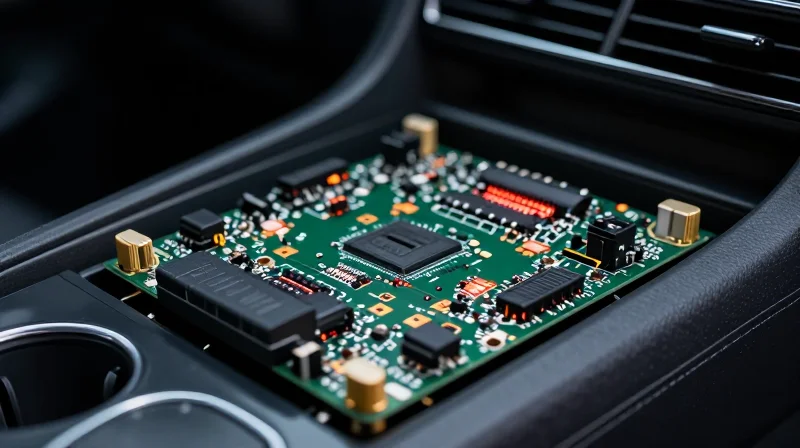
Synergistic Stress Factors in HVAC Environments
Designing control boards for automotive HVAC systems involves navigating the volatile intersection of environmental thermal extremes and continuous structural vibration. Unlike consumer electronics, these units must maintain precise control logic while enduring cold starts at sub-zero temperatures and high-heat operation during summer peak load, often within the same duty cycle. This constant expansion and contraction of materials, exacerbated by road-induced mechanical stress, presents a significant risk for solder joint fatigue and component interconnect failure.
| Environmental Factor | Primary Physical Effect | DFM Mitigation Strategy |
|---|---|---|
| Thermal Cycling | CTE Mismatch Stress | Use of compliant pins and balanced copper pours |
| Mechanical Vibration | Dynamic Solder Fatigue | Underfill application and optimized component mass distribution |
| Humidity Exposure | Electrochemical Migration | Conformal coating and optimized trace spacing |
Addressing Reliability Through Design
To master DFM in this domain, engineers must prioritize robust physical design standards. The interaction between coefficient of thermal expansion (CTE) mismatches—where different materials expand at different rates during temperature swings—is the primary cause of field failure. Ensuring that PCB materials and component packages are matched as closely as possible is critical for long-term reliability.
- How does vibration affect solder joint longevity?
Vibration creates cyclic shear forces on solder joints; if the component is too heavy or the land pattern is undersized, the internal crystal structure of the solder degrades over time, leading to brittle fracture. - Why is thermal cycling more severe in HVAC control units?
HVAC controllers often sit behind the dashboard, where they are subjected to rapid ambient temperature shifts when the cabin heating or cooling systems activate, creating immediate thermal gradients across the PCB. - Can conformal coating mitigate environmental risks?
Yes, high-quality conformal coating provides a barrier against condensation and ionic contamination, which are common when HVAC systems cycle from cold to warm, preventing short circuits and corrosion.
Critical Component Selection for Harsh Environments
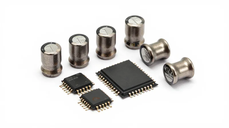
Prioritizing AEC-Q Qualification
The foundation of automotive DFM is the unwavering selection of AEC-Q qualified components. These parts undergo rigorous stress-test qualification regimes defined by the Automotive Electronics Council, specifically targeting failure mechanisms accelerated by the harsh HVAC environment. Designers must treat AEC-Q100 (for ICs) and AEC-Q200 (for passives) as mandatory baselines, not optional suggestions, to avoid premature field failures.
Comparison of Qualification Standards
| Standard | Target Components | Primary Stress Focus |
|---|---|---|
| AEC-Q100 | Integrated Circuits | Thermal cycle, HAST, ESD, Electromigration |
| AEC-Q200 | Passive Components | Flex cracking, thermal shock, vibration |
| AEC-Q101 | Discrete Semiconductors | Power cycling, high-temp reverse bias |
Mitigating Mechanical Failure Risks
Beyond silicon qualification, board-level mechanical integrity is paramount. HVAC controllers are frequently mounted near high-vibration sources such as blower motors and dampers. Utilizing components with robust lead frames or specialized termination designs helps absorb mechanical stress that would otherwise propagate through brittle solder joints.
Common Implementation FAQs
- Can I use Industrial-grade parts if AEC-Q isn't available?
Generally, no. Industrial parts lack the mission-profile validation required for automotive HVAC systems. If a substitute is unavoidable, extensive bespoke validation testing (like ALT/HALT) is required, which rarely offers a lower total cost of ownership than selecting qualified parts initially. - How do I mitigate flex-cracking in ceramic capacitors?
Specify MLCCs with soft-termination (flexible termination) technology. These are designed to deform slightly under mechanical stress, protecting the ceramic body from cracking when the PCB flexes during thermal expansion. - Does component package size affect vibration performance?
Yes; larger components with higher mass possess higher inertia, placing more strain on solder joints during vibration. Whenever possible, standardize on smaller packages (e.g., 0402 or 0603) for passives to improve mechanical resiliency.
PCB Layout Best Practices for High Vibration
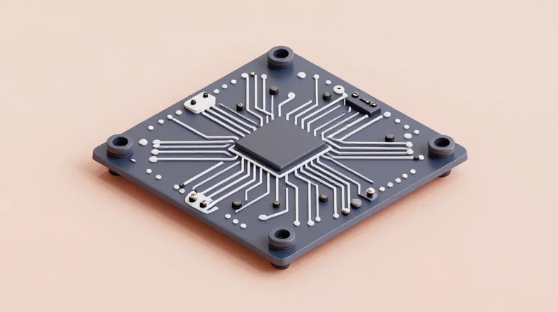
Designing for high-vibration automotive environments requires shifting focus from purely electrical performance to mechanical integrity. When a PCB is subjected to automotive chassis resonance, excessive board deflection can lead to solder joint fatigue, via cracking, and component package fracturing. To survive these conditions, designers must minimize board flexure through strategic component placement, reinforced mounting schemes, and controlled solder fillet geometry.
Component Placement for Mechanical Stability
The mass of a component dictates its acceleration-induced stress on solder joints. Heavy components such as large electrolytic capacitors, power inductors, and connectors act as cantilevers during vibration, amplifying forces at the solder interface. To mitigate this, prioritize placing heavy components close to board mounting points or board supports to minimize the local radius of curvature during board deflection.
| Component Type | Risk Factor | Mitigation Strategy |
|---|---|---|
| Connectors | High | Add through-hole mounting pegs and underfill or adhesive staking. |
| Electrolytic Caps | High | Use radial-leaded types with support clips or low-profile SMT variants. |
| Large ICs (BGA/QFP) | Medium | Increase local copper pour and utilize thermal underfill if required. |
Anchoring and Board Rigidity
The goal is to raise the natural frequency of the PCB assembly above the primary vibration frequencies of the vehicle chassis. This is achieved by maximizing board stiffness and optimizing the mounting pattern.
- Mounting Hole Proximity
Place mounting holes near the corners and along the perimeter at intervals no greater than 50-75mm to prevent localized oil-canning of the board. - Trace Routing near Anchors
Avoid routing high-speed or sensitive signal traces directly adjacent to mounting holes, as strain during fastener tightening or vibration can lead to trace cracking. - Stiffening Ribs
Use double-sided copper planes (even if not electrically necessary) to increase the effective Young's modulus of the PCB laminate.
Solder Joint Reliability FAQ
- Why is BGA underfill critical for vibration?
Underfill redistributes the mechanical stress from the fragile solder balls across the entire component package body, significantly preventing solder joint fatigue during cyclic thermal and mechanical loading. - What is the role of solder fillet geometry?
Concave fillets in SMT components are prone to crack propagation; ensure sufficient solder volume to create a slightly convex fillet, which provides superior resistance to mechanical shock. - How do PTH components differ from SMT?
Plated Through-Hole (PTH) components provide inherent mechanical anchoring, but they are susceptible to barrel cracking if the board flexes; minimize lead-to-hole clearance to prevent excessive pivoting.
Advanced Thermal Management Techniques

Advanced Thermal Management Techniques
Automotive HVAC control units operate under intense thermal constraints, often exacerbated by high-power density requirements and limited airflow. Effective thermal management hinges on creating low-impedance heat paths from power-switching components directly to the PCB's internal ground planes or chassis-coupled heatsinks.
Strategic Stack-Up Design for Heat Dissipation
For HVAC control boards, standard four-layer stacks are often insufficient. Incorporating heavier copper weights (2 oz or higher) on internal ground layers acts as a thermal spreader. Designers should position high-dissipation components such as FETs or motor drivers over these solid copper planes to capitalize on the lateral heat distribution capability of the board.
| Thermal Technique | Primary Benefit | Design Consideration |
|---|---|---|
| Thermal Vias | Lowers Z-axis resistance | Use 0.3mm diameter with 0.8mm pitch |
| Heavy Copper Planes | Increases lateral dissipation | Requires 2oz+ copper thickness |
| TIM Application | Reduces interface resistance | Ensure uniform pressure distribution |
Thermal Via Optimization
Thermal vias serve as the bridge between surface-mounted heat sources and internal heat sinks. To maximize efficacy, keep the via array diameter small (typically 0.2mm to 0.3mm) and avoid filling them with non-conductive materials unless vacuum-pressed. Capping or plating over the vias is recommended to prevent solder wicking during the reflow process, which can lead to solder voids and decreased thermal conductivity.
Frequently Asked Questions on Thermal Reliability
- How does PCB thickness influence thermal performance?
Thicker boards provide higher mechanical rigidity but increase the thermal resistance path. In high-power HVAC applications, thin, high-copper-weight boards often outperform thicker alternatives due to shorter heat paths to the chassis. - When should active cooling be considered for HVAC controllers?
Active cooling is rarely used due to reliability concerns; instead, prioritize 'thermal coupling' to the metallic HVAC housing via high-performance thermal interface materials (TIMs) with high thermal conductivity (>3 W/mK). - What is the risk of excessive solder in thermal pads?
Excessive solder can lead to 'stand-off' issues where the component is lifted from the pad, causing uneven contact and localized hotspots that significantly reduce the MTBF (Mean Time Between Failures) of the power stage.
DFM Rules for High-Volume Assembly
Streamlining High-Volume SMT and Through-Hole Processes
In high-volume automotive production, every millisecond of assembly time and every potential defect costs significantly. To master DFM for HVAC controllers, engineers must prioritize designs that allow for rapid pick-and-place throughput and minimize manual intervention. This involves adhering to standardized component orientations, ensuring sufficient clearances for automated optical inspection (AOI), and designing robust panelization strategies that maximize material utilization while preventing board warpage during reflow.
Comparison of Design Strategies for Manufacturing Yield
| Design Factor | Optimized Practice | Resulting Benefit |
|---|---|---|
| Component Orientation | Consistent alignment | Reduced placement errors |
| Panelization | V-score with tabs | Minimized board stress |
| Fiducial Markers | 3 per panel corner | Enhanced machine alignment |
Frequently Asked Questions
- How does component density impact reflow profile stability?
High component density can create thermal shadows. Engineers should ensure a uniform distribution of components to prevent localized heating issues and ensure consistent solder wetting across the entire board. - Why is board fiducial selection critical for HVAC controllers?
Fiducials allow the vision system of the SMT machine to calibrate accurately. For complex HVAC boards with high pin-count ICs, using local fiducials near fine-pitch components is essential to ensure placement precision within microns. - What is the primary risk of using non-standard panel sizes?
Non-standard sizes often result in wasted laminate material and may require custom-engineered fixtures, which increase both the unit cost and the complexity of the assembly line transition.
Signal Integrity and EMI/EMC Mitigation

Strategies for Signal Integrity in Dense Layouts
Automotive HVAC controllers often integrate low-voltage control signals with high-power MOSFET switching stages, creating significant risks for crosstalk and signal degradation. To maintain signal integrity, designers must prioritize short, controlled-impedance trace routing and maintain continuous ground reference planes. By utilizing a stack-up that minimizes loop areas, engineers can effectively contain radiated emissions while ensuring that high-speed communication buses like CAN-FD remain resilient against transients.
EMI/EMC Mitigation Techniques Comparison
| Mitigation Strategy | Primary Function | Implementation Impact |
|---|---|---|
| Stitched Ground Vias | Reduces ground loop inductance | Moderate board area increase |
| Common Mode Chokes | Suppresses differential noise | High BOM cost, small footprint |
| Snubber Circuits | Dampens switching transients | Significant impact on EMC margins |
Common EMC Design Challenges
- How do I mitigate switching noise from motor drivers?
Utilize dedicated gate drive routing, minimize the switching loop area, and place local ceramic decoupling capacitors as close as possible to the MOSFET drain-source pins. - Is board-level shielding necessary for HVAC boards?
Shielding is typically reserved for critical wireless modules or high-speed processors; however, if conducted emissions exceed CISPR 25 standards, localized metal cans can be an effective DFM solution. - How does PCB stack-up affect EMI?
A high-density stack-up with dedicated ground layers provides the shortest return paths, drastically lowering the loop inductance that leads to radiated noise.
Verification and Testing Protocols
Strategic Verification and Testing Protocols
Verification is the cornerstone of automotive DFM, ensuring that design simulations manifest into robust physical hardware. For HVAC control modules, which operate in harsh thermal and mechanical environments, validation must go beyond standard functional testing to include stress-based life cycle analysis.
Accelerated Life Testing: HALT and HASS
Highly Accelerated Life Testing (HALT) and Highly Accelerated Stress Screening (HASS) are indispensable for identifying failure modes early in the design cycle. By applying multi-axis vibration and rapid thermal cycling, these protocols force latent defects to surface, ensuring the board can withstand the extreme temperature fluctuations typical of automotive cabins.
| Protocol | Primary Objective | Application Stage |
|---|---|---|
| HALT | Identify structural design limits and weak points. | Design Validation (DV) |
| HASS | Screen production units for manufacturing defects. | Production/Manufacturing |
| Thermal Shock | Validate solder joint fatigue resistance. | Design Validation (DV) |
Key Testing Considerations for HVAC Controllers
- How do we validate thermal dissipation claims?
Utilize high-resolution infrared thermography during peak load testing to compare actual board temperature gradients against pre-production thermal simulation models. - What is the role of ICT in high-volume HVAC production?
In-Circuit Testing (ICT) is essential for verifying component polarity, values, and connectivity, significantly reducing latent failure rates at the end-of-line functional test stage. - Why is EMI/EMC compliance testing critical for climate control?
HVAC systems often integrate high-frequency microcontrollers and PWM motor drives; EMC testing ensures these do not interfere with other vehicle control systems or RF communications.
Robust automotive HVAC performance depends on rigorous adherence to DFM standards from the first prototype phase. By integrating vibration-resistant layout strategies and proactive thermal management, your team can ensure long-term reliability in the most challenging automotive environments. Ready to optimize your hardware for the road ahead? Contact our engineering team today to discuss your next high-reliability project.
