In today's fast-evolving tech world, the ability to design and prototype electronic circuits is more accessible than ever. Whether you're an open-source hardware enthusiast, a student, or a seasoned engineer, understanding the ins and outs of PCB design tools is crucial. CircuitMaker, a free offering from the renowned Altium, bridges the gap between complex professional tools and accessible open-source platforms. This article delves into CircuitMaker, exploring its features, advantages, and how it stands alongside its bigger brother, Altium Designer.
What is CircuitMaker?
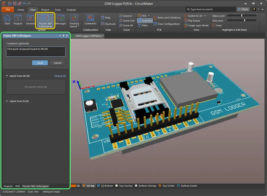
CircuitMaker Software Interface
CircuitMaker, developed by Altium, is a free, cloud-based Printed Circuit Board (PCB) design software, tailored for the maker community, hobbyists, students, and open-source hardware developers. It leverages the powerful Altium Designer engine, providing a sophisticated yet accessible platform for electronic design.
It distinguishes itself from traditional design tools through its community-driven model, fostering collaboration and open sharing of designs. This approach makes it particularly suitable for individuals and teams seeking a cost-effective yet capable tool without compromising functionality.
Key Features of CircuitMaker
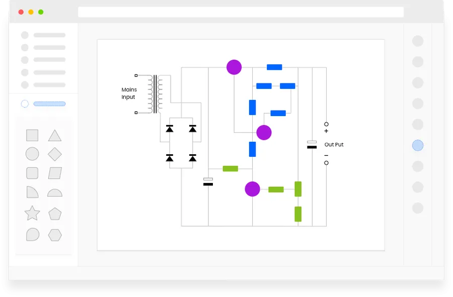
Schematic Design
CircuitMaker, a free PCB design software by Altium, inherits a robust feature set from its professional counterpart, Altium Designer, while maintaining an accessible and streamlined user interface. It is specifically tailored for makers, hobbyists, students, and open-source hardware developers, offering a powerful yet easy-to-use tool for designing electronic circuits.
Schematic Capture CircuitMaker provides an intuitive environment for creating electronic schematics. Users can place components, draw connections, and define electrical properties, all with an easy-to-learn graphical interface. This is crucial for translating circuit ideas into visual representations that can be further developed into a physical PCB layout.
PCB Layout The PCB layout feature allows users to arrange and connect electronic components on a printed circuit board. It includes tools for routing traces, creating vias, defining board layers, and generating manufacturing files, ensuring a smooth transition from design to fabrication. The layout features adhere to industry standards, optimizing for manufacturability.
Extensive Component Library CircuitMaker's cloud-based component library contains a vast selection of electronic parts with detailed specifications and 3D models. This library is regularly updated, which minimizes the need for manual part creation and ensures users have access to accurate, up-to-date information. The availability of a comprehensive component library accelerates the design process.
Cloud-Based Project Management CircuitMaker uses cloud storage to host design projects. This feature enables project collaboration and remote access. Users can share designs, track revisions, and manage multiple projects seamlessly from any internet connected device. The cloud integration is designed to improve productivity and facilitate team-based projects.
Intuitive Interface The software boasts a user-friendly interface that simplifies navigation and operation. The streamlined design enables both novice and experienced users to efficiently access core features. It minimizes the learning curve allowing users to focus on creating their designs rather than deciphering the software.
Integrated SPICE Simulation CircuitMaker offers integrated SPICE simulation capabilities, which allow users to verify circuit functionality before physical prototyping. This ensures the design works as intended, helping to refine and optimize the electrical design prior to manufacturing. SPICE simulations can help save time and resources by reducing design iterations.
CircuitMaker vs. Altium Designer: Key Differences
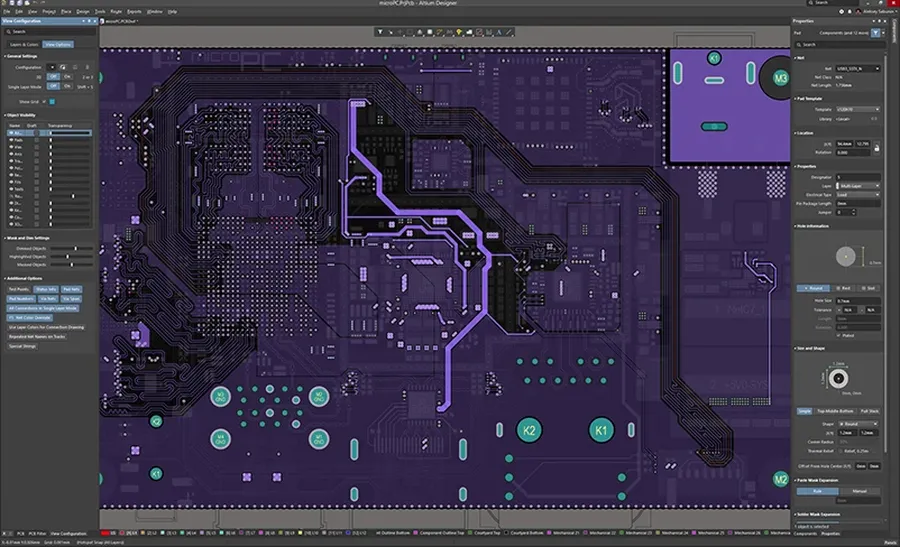
Altium Designer Interface
While both CircuitMaker and Altium Designer are products of Altium, they cater to vastly different user needs and project scales. CircuitMaker is a free, community-focused tool, ideal for hobbyists and makers, whereas Altium Designer is a professional-grade, paid software suite aimed at engineers and corporations. Despite sharing the same underlying Altium engine, their capabilities, features, and cost structures differ substantially.
Professional PCB Designers, Engineers, Corporate Teams
Project Complexity
Suitable for simpler, smaller projects
Handles very complex, multi-layer projects
Component Library
Community-driven, cloud-based library
Comprehensive, managed and proprietary library, with advanced component management
Advanced Features
Limited advanced features, such as advanced routing, signal integrity, and simulation.
Extensive advanced features, including advanced routing techniques, signal integrity analysis, and simulation.
Team Collaboration
Cloud-based collaboration, community oriented.
Advanced collaboration tools for project management and team integration, typically on a larger scale.
Support
Community forums and online resources
Dedicated customer support, training, and professional consultation.
File Compatibility
Compatible with Altium Designer files, but may have limitations with very complex designs
Full compatibility with all Altium Designer files and features
Getting Started with CircuitMaker: A Step-by-Step Guide
PCB Design Flow
This section provides a detailed, step-by-step guide for beginners to quickly get started with CircuitMaker, covering downloading, installation, initial project setup, interface navigation, and the utilization of essential design tools. It is designed to offer a smooth on-boarding experience for new users.
Download CircuitMaker Visit the official CircuitMaker website and navigate to the download page. Ensure you download the correct version for your operating system (Windows). The software is a free download; no payment is required.
Install CircuitMaker Run the downloaded installer file and follow the on-screen instructions. You might be prompted to agree to terms and conditions. It is recommended to install the software in the default directory unless there's a specific need to use a different one.
Account Creation and Login Launch the software, and you'll be prompted to create an AltiumLive account (if you do not have one already). This is essential for using CircuitMaker because all your projects are stored in the cloud. After creating and verifying your account, log in to start using the software.
Creating a New Project Upon successful login, click on 'File' then 'New Project' in the menu. Give a clear and descriptive name to your project and define the project location. CircuitMaker will automatically create project folders and files in that location. You can also create new projects on the Altium 365 workspace.
Navigating the Interface The CircuitMaker interface is composed of schematic and PCB editors. The Schematic Editor is used for designing the circuit diagram, while the PCB Editor is used for designing the physical board layout. The side panels display project components, properties, and other settings.
Using Essential Design Tools The 'Place' menu provides access to schematic and PCB design tools. Start by placing components in the schematic editor. Wire these components to create circuit connections. Once the schematic is complete, you can proceed to design the PCB layout. Use the 'Place' menu to add PCB components. Adjust their placements and routing to complete the PCB layout.
Leveraging the Component Library in CircuitMaker
Component Library
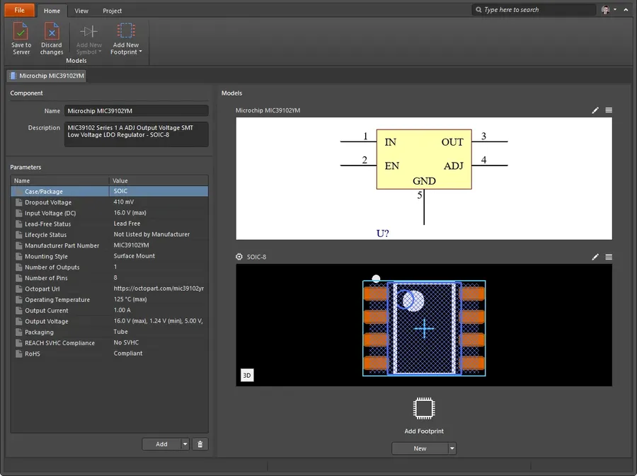
CircuitMaker's component library is a crucial asset for PCB design, providing designers with access to a vast database of electronic parts. This library streamlines the design process, offering pre-defined footprints and schematic symbols, eliminating the need to create components from scratch in many cases. This section will guide you through using this library effectively.
The component library in CircuitMaker allows you to import components from the cloud, create custom components, and manage libraries efficiently. This functionality significantly enhances your design process by providing direct access to a wide range of electronic components, accelerating your PCB design workflow.
Importing Components The library provides access to a vast cloud-based repository of components. To import a component, use the 'Place Component' dialog, search for the required part by keyword or part number and verify the component details before placing it on the schematic.
Creating Custom Components While CircuitMaker has a large built-in library, specific or unique parts might require creating custom components. This involves designing the schematic symbol, PCB footprint, and associating a 3D model. CircuitMaker includes a component editor for creating and saving custom parts into your project or private library for future use.
Component Data Verification Before using any component, whether imported or custom made, ensure that the data is accurate and verified. This involves checking datasheet specifications against the symbol, footprint, and associated data. Incorrect component data can cause design flaws leading to production defects.
Operation
Description
Process
Searching for Components
Find components by keyword, part number, or category.
Use the 'Place Component' dialog; enter search criteria.
Placing Components
Add selected components from library to your design.
Select the component, click the schematic and/or layout.
Verifying Component Data
Ensure that component’s footprint, symbol and parameters match its specifications.
Always compare datasheets and the imported component details.
Creating Custom Components
Design symbols, footprints, and 3D models for unique parts.
Utilize CircuitMaker’s component editor tool.
Component Library Management
Organize and manage component libraries efficiently.
Use the library panel to create, manage and access component libraries.
Collaborating on Projects with CircuitMaker
Collaborative Design
CircuitMaker, with its cloud-based platform, provides a seamless environment for collaborative PCB design. This capability allows teams to work concurrently on projects, enhancing efficiency and fostering better design outcomes through shared knowledge and expertise. The platform’s structure facilitates straightforward access to project files, design progress tracking, and simplifies the iterative design process.
Cloud-Based Project Access All projects are stored in the cloud, ensuring all team members have access to the most current versions, eliminating the risk of version control issues and minimizing the potential for project conflicts.
Real-Time Collaboration Multiple team members can work on the same project simultaneously, enabling parallel design and shortening project timelines. Real-time updates and changes allow for constant feedback and immediate design adjustments.
Project Sharing and Access Control Project sharing is streamlined through the cloud interface, allowing project owners to grant specific team members different levels of access, ensuring only authorized personnel can modify or view sensitive design files.
Design Reviews and Feedback The cloud platform facilitates straightforward sharing of design iterations, enabling efficient design reviews and feedback loops. Team members can provide comments directly on designs, facilitating clear communication and collaborative adjustments.
Centralized Project Management CircuitMaker’s cloud-based system consolidates project management, providing a centralized hub for all project-related activities. This integrated approach simplifies team coordination and keeps all project details and design files in one, easily accessible location.
Frequently Asked Questions about CircuitMaker
This section addresses common queries regarding CircuitMaker, offering clarity on its limitations, ideal use cases, file compatibility with Altium Designer, and available community support channels. This information helps users to effectively leverage the software's capabilities.
What are the primary limitations of Altium CircuitMaker? CircuitMaker, while powerful, has limitations compared to Altium Designer. These include restrictions on the number of layers in a PCB design, limitations on the number of components that can be included in a project, and the inability to import and edit some file formats directly. Furthermore, certain advanced features of Altium Designer, such as complex high-speed routing tools and signal integrity analysis tools, are not included in CircuitMaker.
How does Altium CircuitMaker compare to Altium Designer? CircuitMaker is a free version built on the Altium Designer platform, offering core functionalities such as schematic capture and PCB layout. However, Altium Designer is a professional-grade tool with a more extensive feature set, which includes advanced simulation capabilities, high-speed design options, and a broader array of file format import and export options. CircuitMaker is designed for hobbyists and students, while Altium Designer targets professionals and large enterprises.
What is the cost of CircuitMaker, and is it really free to use? CircuitMaker is indeed free to use for open-source projects, personal or educational use. There are no subscription fees or hidden costs. The trade-off is that it requires your designs to be public and available for other users to access, fostering a collaborative and open-source community. If you need to create private designs, then you need to consider other commercial software solutions.
Can CircuitMaker files be opened in Altium Designer? Yes, CircuitMaker designs can be opened and edited in Altium Designer. This compatibility facilitates a smooth transition for users moving from hobby projects to professional work. However, due to the feature set difference and file format versions, it might be necessary to verify the integrity of the transferred design after importing.
What types of support are available for CircuitMaker users? Support for CircuitMaker is primarily community-based. Users can access forums, online resources, and community channels to find solutions and answers to their questions. Altium does provide some official resources, but the primary approach to support is through collaboration and knowledge sharing among users, making it a self-help learning environment.
Is CircuitMaker suitable for commercial product development? While CircuitMaker is technically suitable for prototyping and initial design phases for commercial products, it's not recommended for large-scale professional projects due to the open nature of the designs and the software's functional limits. If a project needs to be private or requires specific advanced tools, Altium Designer should be considered, as there is a need for a commercial license.
Are there restrictions on the size or complexity of the PCBs I can design in CircuitMaker? Yes, CircuitMaker places some restrictions on PCB design size and complexity. These include a limited number of layers and components compared to professional software. While there isn't a hard size limit, attempting to create extremely large or intricate boards might lead to performance issues. CircuitMaker was designed for mid-complexity PCB designs, for complex design you may need to look at alternative CAD systems.
CircuitMaker for Open-Source Hardware Projects
Open-Source PCB
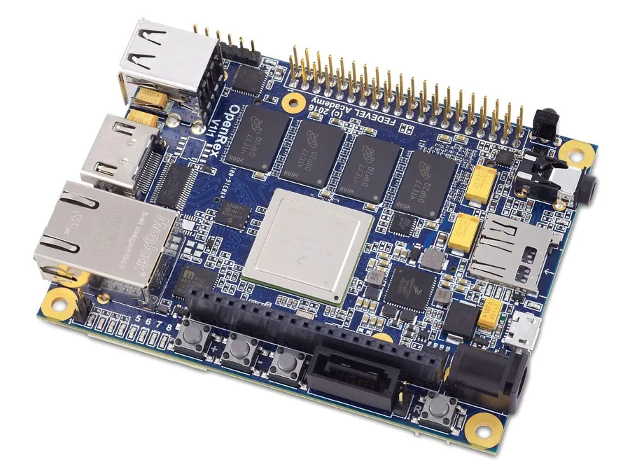
CircuitMaker, provided by Altium, is exceptionally well-suited for open-source hardware projects. Its free access and powerful design capabilities lower the barrier to entry for individuals and teams contributing to the open-source hardware ecosystem. By providing a robust and accessible platform, CircuitMaker allows designers to focus on innovation and collaboration, fostering the growth of the open hardware movement.
Accessibility and Cost-Effectiveness As a free tool, CircuitMaker eliminates the financial hurdles typically associated with professional PCB design software, making it an ideal choice for open-source projects that often operate on limited budgets. This cost-effectiveness allows more people to engage in designing and creating open-source hardware.
Seamless Integration with the Open Source Community CircuitMaker facilitates collaboration through its cloud-based platform, allowing open-source contributors to easily share, access, and iterate on design projects. This feature promotes transparency and communal development, aligning perfectly with the core principles of open-source initiatives.
Extensive Component Library The large component library available within CircuitMaker helps accelerate the design process, and this benefit is a significant plus for the open source community. Designers and contributors are able to focus on innovative design and are not limited by sourcing and creating libraries from scratch.
Contribution and Sharing By using CircuitMaker, designers automatically contribute to the larger pool of designs that can be leveraged by the community. Shared projects act as learning resources and encourage others to create new iterations, driving the open source hardware movement forward.
Advanced Design Features CircuitMaker offers advanced design tools, such as schematic capture, PCB layout, and 3D visualization, all while having an intuitive user interface. This provides all that is required to design for all levels of open-source hardware projects.
Optimizing PCB Designs with CircuitMaker
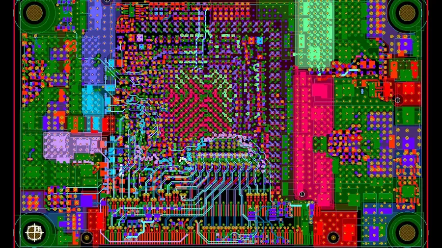
Optimized PCB layout
Optimizing PCB designs in CircuitMaker is crucial for minimizing design flaws, ensuring cost-effective manufacturing, and achieving optimal performance. This involves a combination of strategic planning, adherence to best practices, and leveraging CircuitMaker's features effectively.
Component Placement Strategies Strategic component placement is paramount for minimizing trace lengths, reducing signal interference, and simplifying routing. Group related components logically, and consider thermal management when placing power components. Keep analog and digital circuitry separated to prevent noise contamination.
Efficient Routing Techniques Efficient routing is key to minimizing impedance mismatches and reducing signal reflections. Use the shortest possible traces, minimize vias, and maintain consistent trace widths for critical signals. Employ ground planes for noise shielding and good signal return paths.
Design Rule Checks (DRC) Regularly run DRCs to catch potential errors such as trace spacing violations, insufficient clearances, or unrouted connections. Adhering to the DRC rules ensures a manufacturable and reliable design. CircuitMaker’s DRC function is a critical tool for proactive error prevention.
Layer Stackup Optimization Optimizing the layer stackup is important to control impedance, minimize signal crosstalk, and achieve desired electrical performance. It is important to utilize the minimum number of layers while adhering to the necessary layer requirements. Proper arrangement of power and ground layers also contributes to reduced noise and better power integrity.
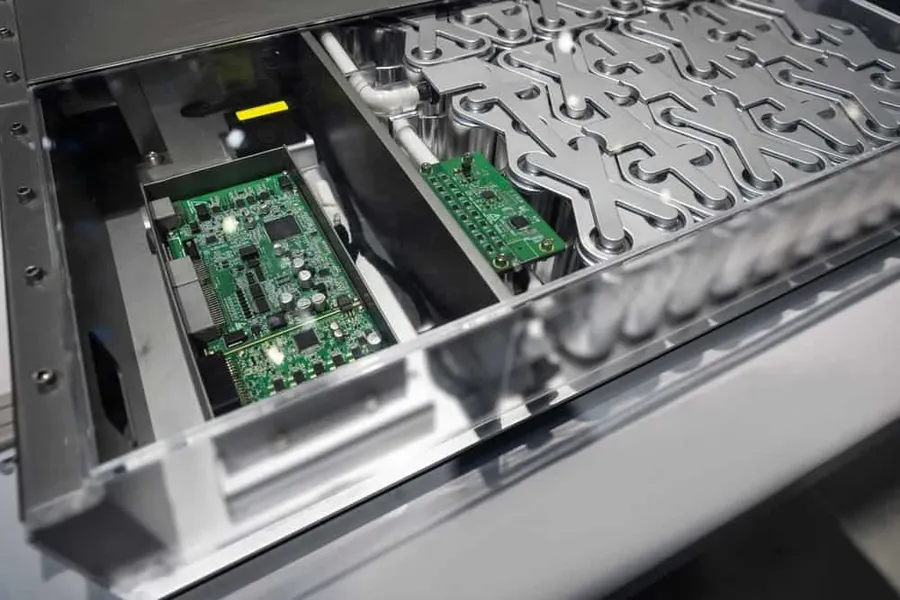
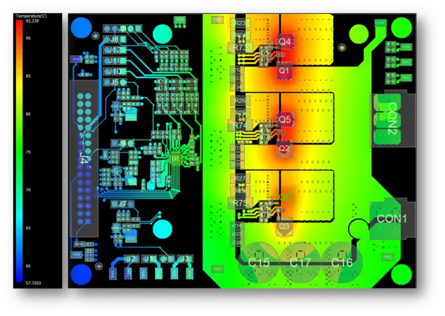
Thermal Considerations Proper thermal design is crucial to ensure the longevity and reliability of your circuit. Use thermal vias and heat sinks where necessary, and plan for adequate airflow around heat-generating components. Proper thermal management is essential for the device to perform to specification
Optimization Area
Best Practices
Benefits
Component Placement
Group related components; separate analog and digital sections
Reduced trace lengths, minimized noise, improved signal integrity
Trace Routing
Use shortest traces; minimize vias; maintain consistent trace width
Reduced impedance mismatches, fewer signal reflections, enhanced performance
Design Rule Checks
Run DRCs frequently; address reported violations
Avoidance of manufacturing errors, increased reliability, enhanced design manufacturability
Layer Stackup
Optimize power and ground layers; control impedance
Improved signal integrity, reduced noise, controlled impedance for critical signals
Thermal Design
Use thermal vias; add heat sinks where necessary; ensure proper airflow
Reduced component temperature, enhanced reliability, extended circuit life
By applying these design principles and taking full advantage of CircuitMaker’s features, you can create more efficient, reliable, and cost-effective PCB designs. Continuous learning and a proactive approach to problem-solving are the keys to mastering PCB optimization in CircuitMaker.
CircuitMaker, powered by Altium, provides a free and highly accessible entry point to the world of PCB design. It is an excellent choice for makers and open source enthusiasts as well as students who want to learn PCB design principles. While it doesn't have all the features of Altium Designer, its intuitive design and core Altium engine make it a solid tool for realizing a wide variety of projects. CircuitMaker continues to evolve, providing a great platform for anyone looking to take their circuit design ideas to the next level. Whether you're designing your first PCB or you're a seasoned designer, CircuitMaker provides a practical starting point with real world applications.