In the realm of electronics, the prototype board is your canvas. Like a rough draft before the final masterpiece, these boards enable you to test, experiment, and refine your circuit designs. From simple LED circuits to complex sensor systems, understanding prototype boards is crucial for any electronics enthusiast or professional. This article delves deep into their types, usage, and best practices, ensuring you're equipped with the knowledge for successful project development.
Understanding the Basics of Prototype Boards
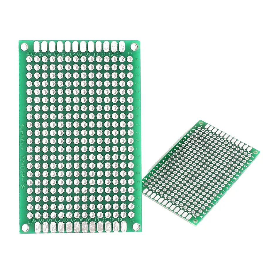
Basic Prototype Board
Prototype boards are fundamental tools in electronics, serving as the crucial link between theoretical circuit designs and functional hardware. They facilitate the rapid testing and refinement of electronic circuits without the permanence of soldering or custom PCB fabrication. At their core, they are platforms designed to allow engineers, hobbyists, and students to experiment and validate their electronic designs before committing to final production.
Types of Prototype Boards: Breadboards vs. Perfboards vs. Custom PCBs
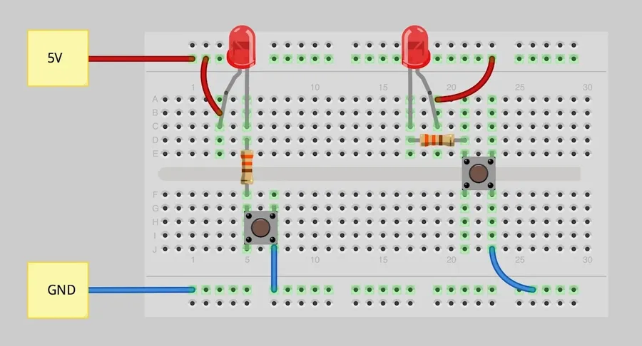
Breadboard Circuit
Selecting the right prototype board is critical for efficient electronic development, with breadboards, perfboards (or stripboards), and custom PCBs each offering unique advantages and disadvantages depending on project requirements. Understanding these differences is essential for optimizing the prototyping process.
Feature
Breadboard
Perfboard (Stripboard)
Custom PCB
Connectivity
Solderless, reusable
Requires soldering
Soldered, permanent
Complexity
Simple circuits, limited components
More complex circuits, moderate component density
Highly complex, high component density
Durability
Fragile connections, not for permanent builds
Robust with soldering, suitable for some permanent builds
Highly durable, suitable for final products
Cost
Low cost for initial setup
Moderate, considering materials and soldering tools
High upfront cost for design and fabrication
Time Efficiency
Fast to assemble and modify
Slower due to soldering
Longest lead time for design and fabrication
Flexibility
Highly flexible for quick iterations
Moderate flexibility after soldering
Limited flexibility after design
Best Use Cases
Learning, quick testing, simple circuit
Intermediate complexity, more robust prototypes
Final products, complex, high-volume circuits
Each of these options plays a distinct role in the prototyping journey, from initial concept validation using breadboards, to iterative development with perfboards, and ultimately to producing finished products with custom PCBs.
Breadboard Deep Dive: Advantages, Limitations, and Best Practices
Components on a Breadboard
Breadboards are fundamental tools in electronics prototyping, offering a solderless and reusable platform for constructing circuits. They are particularly useful for beginners and for rapidly testing circuit designs before committing to a more permanent solution like a PCB. Their ease of use allows for quick modifications and experimentation, making them an essential part of any electronics enthusiast's toolkit.
The primary advantage of a breadboard is its solderless design, which permits components to be connected and reconfigured easily without the need for specialized equipment or time-consuming soldering. However, this advantage comes with limitations, particularly in higher-frequency applications or for circuits requiring low impedance connections, where parasitics can become an issue.
Advantages of Using Breadboards Quick Assembly: Circuits can be assembled and modified rapidly. Solderless Connections: No soldering is required, making it easy to reuse components and change layouts. Reusability: Breadboards and components can be used for multiple projects. Cost-Effective: Breadboards are relatively inexpensive compared to custom PCBs.
Limitations of Breadboards High Parasitic Capacitance and Inductance: May affect high-frequency circuits due to the inherent construction of the breadboard. Not Suitable for High-Power Circuits: Can’t handle high currents or voltages due to the small size of the internal connections. Fragile Connections: Components can come loose easily, leading to intermittent circuit failures. Limited to Through-Hole Components: Can't accommodate surface-mount components.
Best Practices for Using Breadboards Organized Layout: Plan your circuit layout before starting assembly for efficient troubleshooting. Power Rails: Utilize the power rails on the edges of the breadboard for consistent power distribution. Short Jumper Wires: Keep connecting wires short to minimize noise and unwanted signal coupling. Proper Grounding: Ensure proper and reliable grounding connections. Component Placement: Distribute components evenly for better heat dissipation and stability.
Aspect
Description
Component Compatibility
Through-hole components only
Frequency Limitations
Not suitable for high-frequency circuits due to parasitic effects
Current Limitations
Limited current capacity due to internal wire gauge and construction
Durability
Connections can become loose and cause intermittent failures
Application Scope
Best suited for low-power, low-frequency prototype circuits
Perfboard (Stripboard) Techniques: Soldering, Layout, and Best Practices
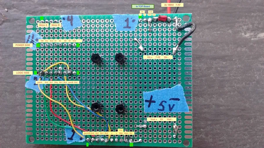
Soldered Perfboard
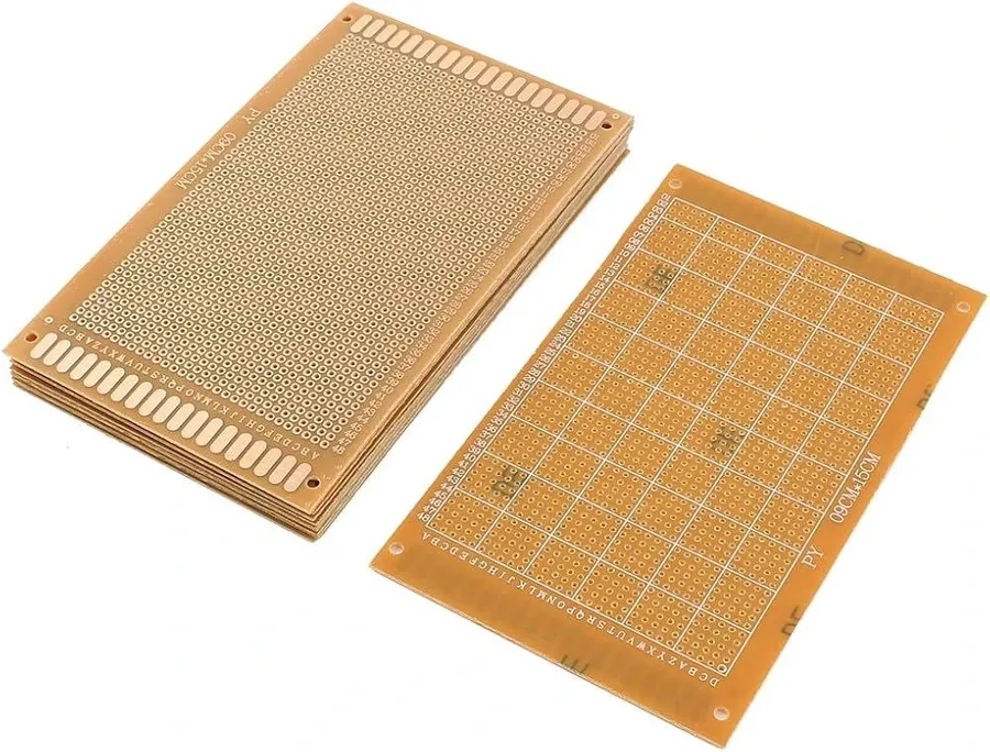
Perfboard, also known as stripboard, offers a more permanent prototyping solution compared to breadboards. It requires soldering components onto copper tracks or pads, creating a more robust and reliable circuit for intermediate to advanced prototyping. This section delves into essential soldering techniques, layout strategies, and best practices for using perfboard effectively.
Soldering Techniques for Perfboard Proper soldering is crucial for reliable perfboard circuits. This includes heating both the component lead and the pad simultaneously, applying solder to the joint, and avoiding cold solder joints by ensuring a shiny, smooth solder fillet. Use appropriate solder wire with flux, a temperature-controlled soldering iron with a fine tip, and take measures to prevent overheating components.
Effective Perfboard Layout Strategies Careful planning of component placement is essential. Organize your layout before soldering by considering the current path and shortest connections, which can minimize noise and enhance the circuit's performance. Avoid complex wire runs and optimize placement to minimize crossover, and use jumpers or wire bridges to make necessary connections.
Best Practices for Robust Perfboard Circuits Ensure mechanical stability and strain relief by securing components properly; where appropriate, use heat-shrink tubing on exposed wires to ensure they do not touch. Additionally, always double-check every solder joint with a multimeter to ensure electrical connections are correct and to identify any unintended short circuits. Consider using sockets for integrated circuits to reduce the need for re-soldering during debugging.
Technique
Description
Benefit
Pre-Planning
Plan component placement before soldering.
Minimizes errors and optimizes layout efficiency.
Proper Soldering
Heat pad and component lead simultaneously; apply solder to joint.
Ensures strong, reliable electrical connection.
Strain Relief
Secure wires and components to prevent breaks.
Increases long-term reliability and prevents damage.
Multimeter Testing
Verify continuity and check for shorts using a multimeter
Ensures that the design matches the intended schematic.
Designing Your Own Prototype PCB: When and How
Custom PCB Prototype
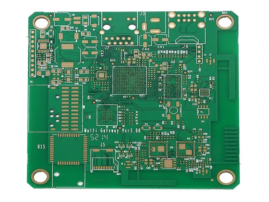
Transitioning to a custom Printed Circuit Board (PCB) from breadboards or perfboards marks a significant step in electronic prototyping, indicating a move towards more complex, reliable, and potentially manufacturable designs. This section outlines the considerations for this transition, covering the 'when' – the circumstances prompting the need for a PCB – and the 'how' – the process of designing and fabricating one.
The decision to design a custom PCB is driven by the project’s increasing complexity and the limitations of simpler prototype boards.
When to Consider a Custom PCB: Several key factors suggest it's time to move to a custom PCB including: Circuit complexity (Many components or intricate interconnections), Signal Integrity (Critical signal paths requiring controlled impedance), Reliability (A robust and durable design is needed), Volume production (PCB's are essential for mass production), Project Maturity (Once the design is relatively stable and unlikely to change)
Designing a PCB involves schematic capture, layout design, and finally fabrication. There are numerous tools available, each with advantages and disadvantages.
PCB Design Tools
Pros
Cons
Eagle
Free for hobbyist use, large component library, user-friendly
Subscription model for professional use, sometimes difficult to use advanced features
KiCad
Open-source, completely free, feature-rich
Steeper learning curve than some alternatives
Altium Designer
Industry-standard, powerful features, excellent support
High cost, complex interface
EasyEDA
Web based and free, easy to collaborate and share
Dependant on internet connection, limited advanced features
Once the design is complete, you have several options for fabrication, from small-batch prototype runs to full-scale production. Selecting the correct fabrication process is as important as designing the board.
PCB Fabrication Options: Online PCB manufacturers offer a range of services, from basic prototyping to complex multi-layer boards. Consider turn-around time, cost, and quality when making a decision. Also, local PCB manufacturers may offer faster turn around times and better personalized service, but they may come at a higher cost.
Choosing the Right Prototype Board: A Comparative Analysis
Selecting the appropriate prototype board is crucial for the success of any electronics project, as it directly impacts development efficiency, cost, and the final product's reliability. This section provides a detailed comparative analysis of various prototype boards, considering factors such as project complexity, budget, and time constraints, to help engineers make informed decisions.
Feature
Breadboard
Perfboard (Stripboard)
Custom PCB
Complexity
Best for simple circuits, quick testing
Suitable for moderately complex circuits, more permanent than breadboards
Ideal for complex and professional circuits, production-ready
Durability
Not durable, for temporary prototyping
More durable than breadboards, suitable for semi-permanent prototypes
Highly durable, for final product or robust prototypes
Cost
Low cost, reusable
Moderate cost, requires soldering
High upfront cost, economical at scale
Time Commitment
Fast setup, no soldering required
Moderate time investment due to soldering
Longer lead time due to design and fabrication processes
Partially reusable, components generally soldered in place
Not reusable, for one-time production, can be iterated through redesigns
Signal Integrity
Moderate signal integrity, may not be ideal for high-frequency circuits
Improved signal integrity, good for moderate frequency circuits
Excellent signal integrity, suitable for high-frequency circuits and sensitive applications
Flexibility
High flexibility in component placement
Limited flexibility, component placement dependent on strip arrangement
Very flexible in component placement and circuit design
The selection of a prototype board involves a trade-off. Breadboards are excellent for initial proof-of-concept and rapid iterations due to their reusability and ease of use. Perfboards offer a more permanent solution with increased robustness, suitable for more stable prototypes where soldering is acceptable. Custom PCBs are essential for projects requiring high complexity, reliability, and optimal signal integrity. The project's maturity, requirements, available budget, and timeline will be the deciding factors in selecting the appropriate method.
Prototype Board Materials and Quality Considerations
Prototype Board Materials
The selection of materials and the overall quality of a prototype board are paramount to the reliability and longevity of the circuits they host. A thorough understanding of these aspects ensures the development of robust prototypes that accurately reflect the final intended product.
Prototype boards are commonly constructed from a variety of materials, each influencing performance and durability. The most frequently encountered base materials are:
Paper Phenolic Also known as FR-2, this is an inexpensive material often used in entry-level perfboards. It is cost-effective but offers limited mechanical strength, poor moisture resistance, and is not suitable for high-temperature applications. Its lower quality is reflected in its price point and is more suitable for less demanding applications.
Glass Epoxy (FR-4) A more robust option, FR-4 offers superior mechanical strength, better moisture resistance, and can withstand higher temperatures compared to paper phenolic. It is the standard material used in most professional PCBs and provides a higher level of reliability. Although more costly than FR-2, it is the optimal choice for projects requiring higher performance and durability.
Composite Materials Some prototype boards use composite materials, often incorporating both paper and fiberglass for a balance of cost and performance. These are often a middle ground offering better performance than paper phenolic and lower cost compared to FR-4, but with limitations in durability compared to FR-4.
The quality of the prototype board is influenced by factors beyond the base material, such as:
Trace Quality The quality of copper traces is essential. Poorly etched or low-quality copper can lead to increased resistance and signal loss, impacting the functionality of the circuit, especially in high-frequency designs. High-quality boards have uniformly etched traces with consistent width.
Plating Quality Surface plating, often tin or gold, protects the copper from corrosion and ensures reliable solder connections. Poor plating can result in oxidation and weak solder joints which will result in bad connections, thereby reducing the life of the prototype.
Hole Quality The diameter and consistency of plated through-holes (PTH) are crucial for inserting components easily. Misaligned holes or poorly plated through-holes can make soldering difficult and compromise circuit performance. High-quality boards have consistent hole sizes and diameters, ensuring reliable connectivity.
Material
Cost
Mechanical Strength
Moisture Resistance
Temperature Resistance
Typical Use Cases
Paper Phenolic (FR-2)
Low
Low
Poor
Low
Simple, low-cost projects, educational purposes
Glass Epoxy (FR-4)
Moderate
High
Good
High
Professional prototypes, demanding applications
Composite Materials
Low to Moderate
Moderate
Moderate
Moderate
General purpose, hobbyist projects
Selecting the correct material and high quality board will not only extend the life of your prototype but also reduce debugging time due to more reliable components and more predictable circuit behaviour. Choosing higher quality boards can often justify its cost in terms of a more effective and efficient prototyping process.
Frequently Asked Questions About Prototype Boards
This section addresses common inquiries regarding prototype boards, providing concise answers to help you understand their usage, types, and applications in electronics prototyping.
What exactly is a prototype board? A prototype board, also known as a protoboard, is a platform used to build and test electronic circuits. It allows for the temporary connection of electronic components without the need for soldering, facilitating experimentation and circuit design verification. Common types include breadboards and perfboards, each catering to different stages of prototyping.
What is the primary use of a protoboard in electronics? The primary use of a protoboard is to enable rapid prototyping and testing of electronic circuits. It allows designers and engineers to quickly assemble, modify, and test circuits before committing to a final design on a printed circuit board (PCB). Protoboards are instrumental in the initial phases of project development.
What is a perfboard and how does it differ from a breadboard? A perfboard, also called a stripboard, features a grid of holes with copper traces connecting columns or rows. Unlike a breadboard, components on a perfboard are typically soldered into place, creating more stable and permanent connections than a solderless breadboard. Perfboards are suitable for more robust prototypes that are closer to a final PCB design and can be used for circuits that will have long-term testing.
How do I build a circuit using a prototype board? To build a circuit on a breadboard, insert components and use jumper wires to connect them, following the circuit diagram. On a perfboard, components are placed and soldered, connecting them with wires or by using the copper traces. Begin with simple circuits to ensure proper connections before progressing to more complex builds. Ensure components are placed correctly (orientation matters) and securely. Always verify your circuit before energizing it.
When should I consider using a custom PCB instead of a prototype board? Custom PCBs are typically considered when a design is finalized, the circuit has been thoroughly tested on a prototype board, and you need a more robust, compact, and reliable final product. Moving to a custom PCB also provides opportunities for optimizing manufacturing and design for scale.
Is soldering required when using a prototype board? Soldering is not required for all types of prototype boards. Breadboards are solderless, relying on spring-loaded contacts to secure components. However, perfboards (stripboards) and custom PCBs require soldering to make permanent connections. The choice depends on the stability and permanency needed for the circuit.
What materials are commonly used in prototype boards, and how does quality affect performance? Prototype boards, such as breadboards, often use a plastic or composite material with spring-loaded metal clips for connections. Perfboards utilize materials such as phenolic or fiberglass, with copper traces. The quality of these materials impacts durability, conductivity, and the overall reliability of the circuit. Higher-quality boards often feature better contact materials, resulting in less signal loss and more consistent performance. For example, using gold-plated contacts in a breadboard can reduce contact resistance compared to tin-plated contacts.
Advanced Prototyping Techniques: Tips and Tricks
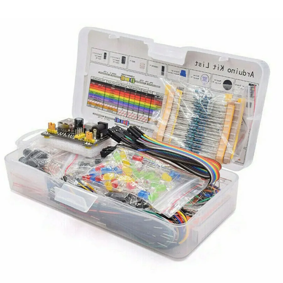
Advanced Prototype
Mastering advanced prototyping techniques is crucial for efficiently developing robust and reliable electronic circuits. This section delves into strategies for optimizing the prototype process, focusing on testing, debugging, and implementation of complex projects, thereby bridging the gap between initial design and a polished, functional prototype.
Modular Design Approach Break down complex projects into smaller, manageable modules. This approach facilitates easier testing and debugging of individual components before integrating them into the larger system, minimizing troubleshooting complexities.
Strategic Component Placement Optimize component placement on the prototype board to minimize signal interference and ensure efficient signal flow. This includes grouping related components and separating sensitive analog circuits from digital circuitry to enhance circuit stability.
Rigorous Testing Procedures Implement a thorough testing protocol at each stage of development. This involves using appropriate test equipment, such as multimeters and oscilloscopes, to verify signal integrity, voltage levels, and current consumption. This strategy is vital for identifying potential issues early on.
Effective Debugging Methods Adopt systematic debugging strategies such as signal tracing, breakpoint analysis, and using logic analyzers to pinpoint and resolve circuit malfunctions efficiently. This includes isolating issues to specific components or sections of the circuit.
Utilizing Simulation Software Employ simulation software to model circuit behavior before physical implementation. This enables early identification of design flaws and enhances optimization, preventing costly mistakes in the physical prototyping phase.
Power Supply Management Implement robust power management strategies, including the use of decoupling capacitors and voltage regulators. This approach mitigates noise and ensures a stable power supply to all components, which is essential for reliable circuit operation.
Documentation and Version Control Maintain detailed documentation of every prototype version, changes made, and test results. Utilize version control systems to manage modifications and track progress systematically. This ensures that design changes are well-managed and easy to revert, if necessary.
The prototype board is the heartbeat of electronics development, it’s the gateway to bringing ideas to life. Whether you’re a hobbyist or a seasoned engineer, mastering the art of prototyping is essential. By understanding the different types of prototype boards, including breadboards, perfboards, and custom PCBs, you can effectively transform your ideas into functioning electronic circuits. Embrace the flexibility and adaptability of prototype boards to make your projects a success, and always remember that the journey of innovation begins with a prototype.