Relay electronics, the unsung heroes of electrical control, bridge the gap between low-power control signals and high-power circuits. Much like a traffic controller directing vehicles, relays ensure the smooth and safe operation of countless devices. From the simple click of a light switch to the complex choreography of industrial machinery, relays are indispensable. This article unravels the core principles of relay electronics, offering a roadmap for anyone seeking to understand and apply this fundamental technology. We will explore the underlying mechanics, various types, and diverse applications, providing you with practical knowledge to elevate your understanding and skills in electronics.
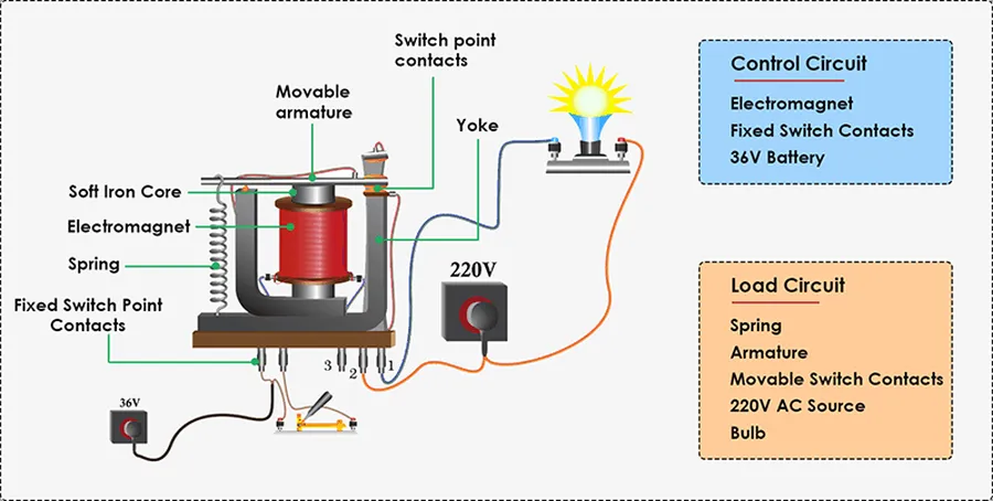
Relay electronics centers on electromechanical relays, devices that use an electrical signal to control a mechanical switch. This fundamental process allows for the control of high-power circuits using low-power signals, a critical function in many electronic applications. The core operation of a relay involves an electromagnet, an armature, and contact points, each playing a vital role in enabling circuit control.
The relay's functionality is rooted in the principles of electromagnetism. When an electrical current is passed through the relay's coil, it generates a magnetic field. This field then acts on a ferrous armature, causing it to move. The movement of the armature then either opens or closes the contact points, thereby switching the circuit. This mechanism enables the relay to control a different electrical circuit, completely isolated from the control circuit. The precise design and materials used for the electromagnet, armature and contacts determine the performance characteristics of the relay.
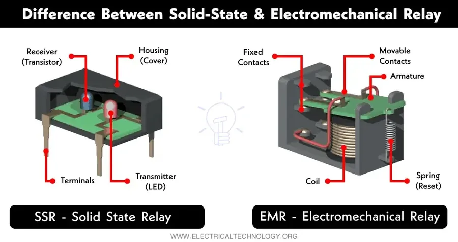
Relays, essential components in electronic circuits, come in various forms, each designed for specific applications. This section explores the primary types of relays, namely electromechanical relays (EMRs), solid-state relays (SSRs), reed relays, and thermal relays, outlining their operational principles, advantages, disadvantages, and typical applications.
| Relay Type | Principle of Operation | Advantages | Disadvantages | Typical Applications |
|---|---|---|---|---|
| Electromechanical Relays (EMRs) | Uses an electromagnet to mechanically move contacts. | High current handling capability, cost-effective, simple to implement. | Slower switching speeds, mechanical wear, larger size, audible click. | General-purpose switching, automotive, industrial control, appliance control. |
| Solid-State Relays (SSRs) | Uses semiconductor devices to perform switching. | Fast switching, no moving parts, longer lifespan, quiet operation. | Higher cost, greater heat generation, susceptible to overvoltage. | Industrial control, heating systems, lighting control, applications requiring high switching speeds. |
| Reed Relays | Uses a magnetic field to activate contacts within a glass tube. | Fast switching, low contact resistance, small size, hermetically sealed contacts. | Low current handling capability, susceptible to mechanical shock. | Instrumentation, telecommunications, high-frequency switching. |
| Thermal Relays | Operated by thermal expansion of a bimetallic strip. | Simple, inexpensive, reliable in overload protection. | Slow response time, not precise. | Motor overload protection, circuit breakers, time delay circuits. |
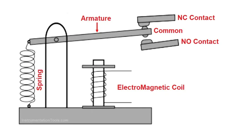
Electromechanical relays (EMRs) are fundamental switching devices that use an electromagnetic force to mechanically operate a set of contacts. This functionality allows for the control of high-power circuits using low-power control signals, making them indispensable in numerous applications. Understanding their construction and operation is crucial for effective circuit design and implementation.
The core of an EMR consists of an electromagnet, an armature (a movable iron piece), and contact points. When a current flows through the electromagnet's coil, it generates a magnetic field. This magnetic field attracts the armature, causing it to move and either open or close the electrical contacts. This mechanical action allows the relay to switch one or more circuits. EMRs are defined by their contact configurations, the most common of which are normally open (NO), normally closed (NC), single-pole single-throw (SPST), and double-pole double-throw (DPDT).
| Configuration | Description | Schematic Representation |
|---|---|---|
| Normally Open (NO) | Contacts are open when the coil is de-energized. They close when the coil is energized, allowing current to flow. | NO contacts.png |
| Normally Closed (NC) | Contacts are closed when the coil is de-energized. They open when the coil is energized, interrupting current flow. | NC contacts.png |
| Single-Pole Single-Throw (SPST) | This type has one set of contacts that can either be open (NO) or closed (NC). It acts as a simple on/off switch. | SPST relay.png |
| Double-Pole Double-Throw (DPDT) | This configuration has two sets of contacts that can be switched simultaneously. It allows the control of two circuits independently or the selection of two different signal paths. | DPDT relay.png |
The selection of an appropriate EMR depends largely on the needs of the particular application, based on how the electrical circuit is required to operate. A good understanding of the contact configurations above will ensure the selected relay can provide the function required.
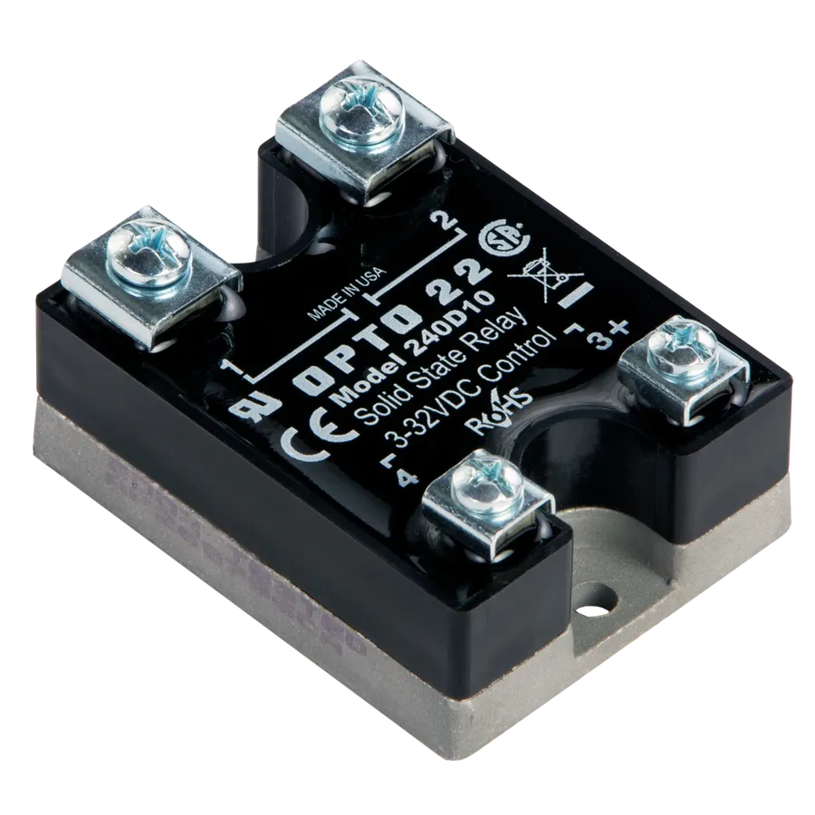
Solid State Relays (SSRs) represent a significant advancement in relay technology, leveraging semiconductor components to perform switching functions. Unlike electromechanical relays (EMRs), SSRs have no moving parts, leading to enhanced operational characteristics that make them suitable for many modern applications. SSRs provide a highly reliable and efficient alternative, utilizing transistors, thyristors, or other semiconductors as the switching element, thereby enabling the precise control of electrical circuits without mechanical contact.
| Feature | Solid State Relay (SSR) | Electromechanical Relay (EMR) |
|---|---|---|
| Switching Speed | Very Fast (microseconds to milliseconds) | Slow (milliseconds to seconds) |
| Lifespan | Long (millions of cycles) | Shorter (hundreds of thousands of cycles) |
| Noise | Silent operation | Audible click during switching |
| Contact Bounce | No contact bounce | Present during switching |
| Size | Smaller footprint | Larger |
| Mechanical Wear | None | Present |
| Vibration Sensitivity | Less sensitive | More sensitive |
| Arcing | No arcing during switching | Possible arcing, particularly with DC |
While SSRs offer numerous advantages, they also have limitations. SSRs typically exhibit higher on-state resistance than EMRs, which translates to increased heat generation and reduced efficiency in high current applications. Additionally, SSRs may have limitations in withstanding high transient currents, and certain types can exhibit some off-state leakage current. It is important to select an SSR based on application requirements and take its limitations into account.
Understanding relay specifications is crucial for selecting the correct component for a given application and preventing operational failures. These specifications define the electrical and environmental limits within which a relay can operate reliably and safely. Proper matching of relay specifications with project requirements is paramount to ensure both performance and longevity.
| Specification | Description | Importance |
|---|---|---|
| Coil Voltage | The voltage required to energize the relay coil, measured in volts (V). | Ensuring the coil voltage matches the driving circuit voltage prevents damage or failure to operate. |
| Contact Current Rating | The maximum current that the relay contacts can safely switch, measured in amperes (A). | Exceeding the current rating will cause contact damage or failure, potentially causing overheating and fire risk. |
| Isolation Voltage | The maximum voltage that the relay can withstand between its coil and contacts without dielectric breakdown, often measured in kilovolts (kV). | Essential for safety, particularly in high voltage applications, preventing arc-overs and ensuring isolation between circuits. |
| Operating Temperature | The temperature range within which the relay can operate safely and reliably, typically specified in degrees Celsius (°C). | Operating beyond the specified limits can cause reduced performance, material degradation and premature failure. Consider application temperature requirements, environmental temperature and also the temperature rise during operation. |
| Contact Resistance | The resistance of the closed relay contacts to electrical current, measured in ohms (Ω) or milliohms (mΩ). | A lower resistance provides a more efficient contact, reducing voltage drops and heat generation. Increased resistance due to wear or oxidation can lead to reduced performance or even a contact failure. |
| Response Time | The time delay before the contacts close or open after the coil is energized or de-energized, measured in milliseconds (ms). | Crucial for applications requiring rapid switching, especially when used in high speed applications. |
| Mechanical Life | Number of operations a relay can perform without an electrical load. | Indicates the component's operational endurance, crucial for high-cycling or long-term use and for maintenance requirements. |
| Electrical Life | Number of operations a relay can perform at its rated electrical load. | Indicates the component's operational endurance when used at specified electrical loads. Performance degradation can be expected and considered for maintenance schedules. |
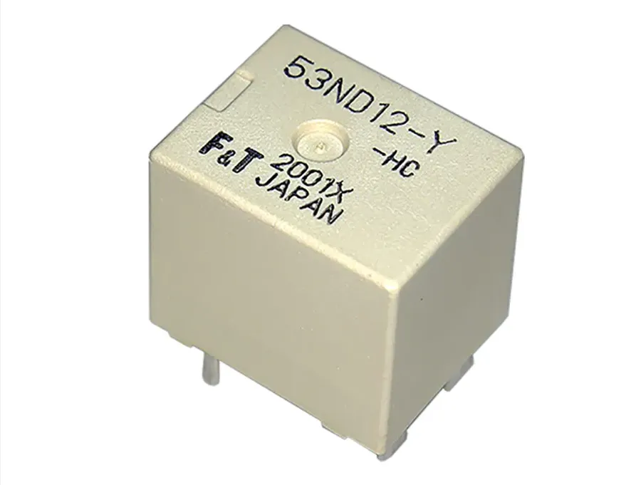
Relays are ubiquitous components in modern electrical and electronic systems, serving as crucial intermediaries for circuit control across a wide spectrum of industries. Their ability to use a low-power signal to control a high-power circuit makes them indispensable in diverse applications, from the most delicate electronic devices to heavy-duty industrial machinery. The following sections will illustrate a range of applications, highlighting both the versatility and necessity of relay technology.
| Industry | Application | Specific Examples | Benefits of Relay Use |
|---|---|---|---|
| Automotive | Control of vehicle systems | Starter motor control, headlight activation, power window operation, fuel pump activation, turn signal circuits, anti-lock braking systems (ABS) | Efficient power management, circuit protection, allows low-current switches to control high-current devices, provides electrical isolation |
| Industrial Automation | Process and machinery control | Motor control, conveyor belt operation, robotic arm control, emergency stop systems, programmable logic controllers (PLCs), heating and cooling systems. | Safe and reliable control of high-power equipment, automation of complex sequences, improved system reliability, isolation of control circuits from high power circuits. |
| Home Appliances | Switching and control of appliances | Control of motors in refrigerators and washing machines, heating elements in ovens, timers in microwaves, power control in air conditioners, lighting control systems. | Safe and reliable control of appliances, ability to handle high-power loads, increased device lifespan, allows for remote control and automation |
| Telecommunications | Signal routing and switching | Telephone exchanges, signal routing in networks, remote control of communication equipment, antenna switching systems. | Reliable signal routing, switching of multiple circuits, enables remote control of devices, provides signal isolation and signal integrity. |
| Aerospace | Aircraft control systems | Flight control surfaces, landing gear activation, engine control systems, lighting systems, emergency power transfer | High reliability, resistance to vibration and temperature variations, ability to handle critical functions, electrical isolation. |
| Power Generation and Distribution | Control of high-voltage circuits | Circuit breakers, switchgear, power transformer control, load shedding systems, backup power systems | Provides safe control of high-voltage circuits, automatic switching and protection functions, fault isolation. |
| Renewable Energy Systems | Power conversion and control | Solar panel array switching, wind turbine control, battery charging circuits, grid integration systems. | Optimized power management, safe and efficient switching of power sources, enables integration of renewable energy into existing infrastructure. |
Selecting and implementing relays correctly is crucial for system reliability and performance. This section provides actionable guidance on choosing the appropriate relay, understanding datasheets, ensuring correct wiring practices, and implementing protective measures against electrical transients using a flywheel diode.
Relays, while robust, are susceptible to various failures. Understanding common issues and employing effective troubleshooting techniques using a multimeter is critical for maintaining reliable electronic systems. This section outlines common problems such as relay failure, contact wear, and coil burnout, and provides strategies to identify and resolve them.
Effective troubleshooting requires a systematic approach using a multimeter. The multimeter is used to check the coil resistance, contact continuity, and voltage levels of the relay circuits, these are the key parameters for relay fault detection.
| Troubleshooting Steps | Multimeter Measurement | Interpretation and Action |
|---|---|---|
| Check Coil Resistance | Measure resistance across relay coil terminals. | Open circuit or a value far from rated suggests coil burnout; replace relay. Low resistance suggests short, investigate wiring and relay. |
| Verify Contact Continuity | Measure resistance across NO/NC contacts in deactivated/activated states. | Infinite resistance where continuity should be, suggests contact wear or sticking. A reading indicating continuity when contacts should be open requires further investigation. |
| Test Coil Voltage | Measure voltage across the coil when relay should be energized. | No or low voltage suggests wiring issue or control circuit problem; high voltage suggests excess supply, which requires voltage regulation. |
| Check Wiring Integrity | Measure resistance through wires and connections. | High resistance suggests poor or broken wiring, fix faulty connections. Confirm wiring connections against the schematic to avoid miswiring. |
This section addresses common questions regarding relay electronics, providing concise and authoritative answers to enhance understanding and practical application.
Relay electronics form the backbone of numerous electrical systems, enabling the reliable control of diverse applications. From understanding the fundamental working principles to knowing how to choose the correct relay and diagnose typical problems, this guide provides the knowledge to master this essential technology. As industries continue to evolve, the role of relay electronics will remain vital, serving as a cornerstone of both current and future technological advancements. With this insight, you're better equipped to navigate the world of relay electronics, confidently applying their advantages in your own projects and designs.

