Transformers, the unsung heroes of electrical distribution, rely on a symphony of interconnected parts to perform their critical task of stepping up or stepping down voltage levels. Much like the human body where each organ serves a distinct purpose, every component of a transformer plays a unique role in ensuring efficient power transfer and distribution, from the robust core to the intricate windings. This article delves into a comprehensive exploration of these components, unveiling their functions and the vital roles they play in the grand scheme of electrical systems.
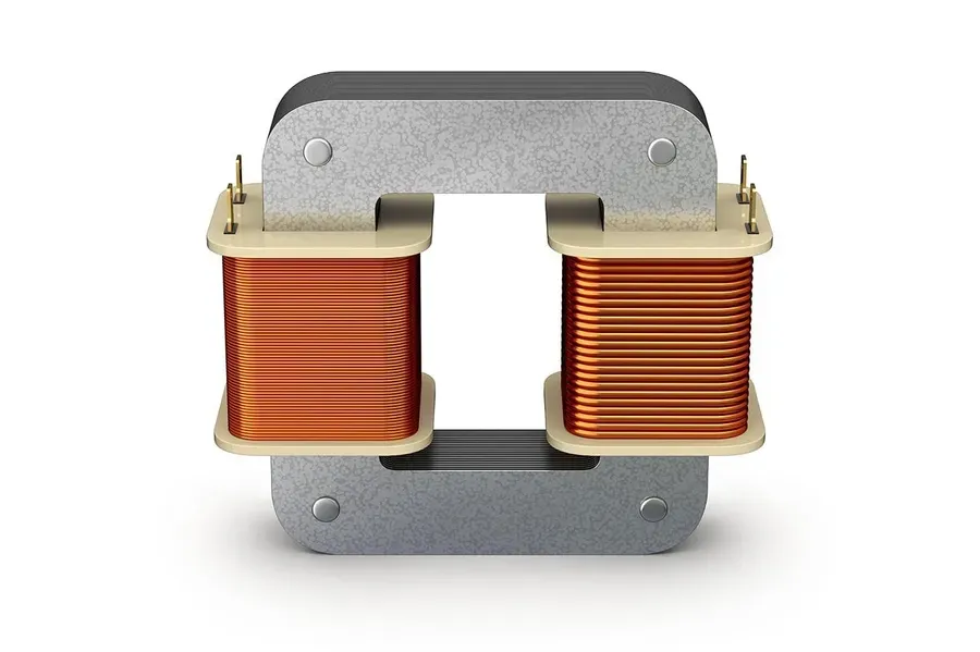
The transformer core is the foundational element that facilitates efficient magnetic flux transfer between the primary and secondary windings. Typically constructed from laminated steel sheets, the core provides a low reluctance path for the magnetic flux, minimizing energy loss and optimizing the transformer's performance. The material and design of the core are critical factors in determining the transformer's efficiency and operational characteristics.
| Feature | Description | Importance |
|---|---|---|
| Material | Laminated Steel (often silicon steel) | Reduces eddy current losses, enhances permeability |
| Structure | Laminated sheets stacked together | Minimizes eddy currents and heat generation |
| Function | Provides low-reluctance path for magnetic flux | Enables efficient transfer of energy |
| Impact on Efficiency | Directly affects efficiency and performance | Lower core losses result in higher transformer efficiency |
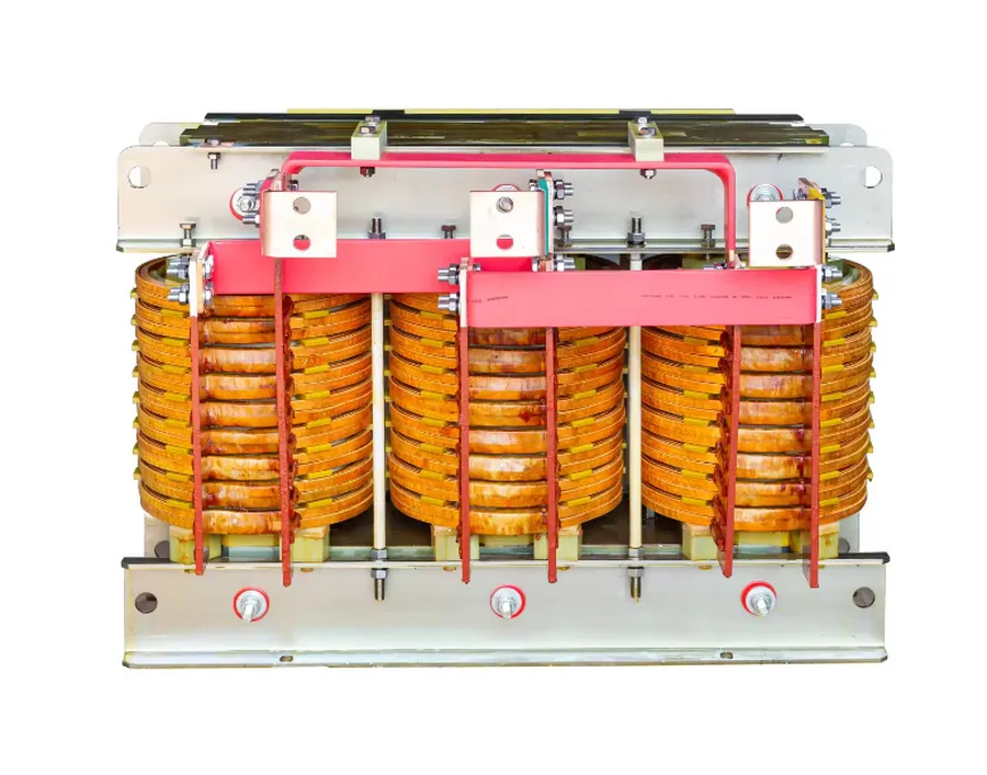
Transformer windings are the core components that facilitate the transfer of electrical energy. These windings, typically made of copper or aluminum wire, are carefully arranged to create magnetic fields and induce voltage transformations. The primary winding, connected to the source, generates a magnetic flux, while the secondary winding, linked to the load, captures this flux to produce an altered output voltage, thereby enabling the fundamental transformer action.
| Feature | Primary Winding | Secondary Winding |
|---|---|---|
| Function | Receives input voltage and generates magnetic flux | Intercepts magnetic flux and produces output voltage |
| Connection | Connected to the power source | Connected to the load |
| Voltage | Typically has higher turns for step-down transformers | Typically has lower turns for step-down transformers |
| Current | Carries the input current | Carries the output current |
| Magnetic Flux | Generates the magnetic flux | Captures the generated magnetic flux |
The configuration of windings is crucial to achieving the desired voltage transformation. Transformers can be designed with a variety of winding types, including concentric, spiral, and helical windings, each suited to specific power levels and operating conditions. Concentric windings, for instance, involve layering the primary and secondary windings concentrically around the core, whereas spiral windings are laid flat in a spiral configuration, which is often preferred for high-voltage applications.
The selection of winding material is determined by electrical conductivity, mechanical strength, and cost-effectiveness. Copper is the most commonly used winding material due to its high electrical conductivity and ductility, while aluminum, due to its lower density, can be used to reduce the weight and cost of the transformer in certain applications. Proper winding design includes considerations for insulation, thermal expansion, and mechanical stress to ensure the longevity and reliability of the transformer.
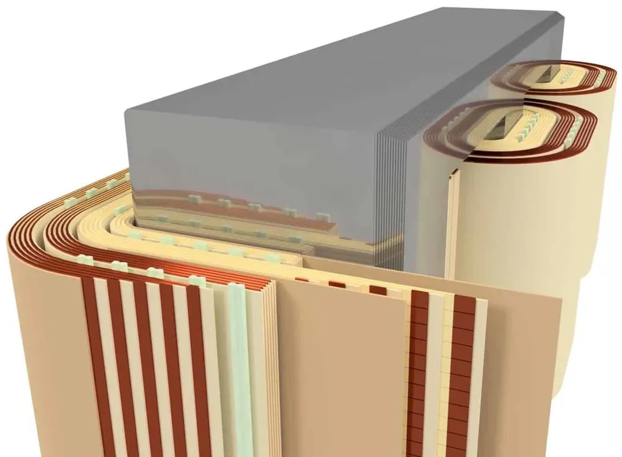
Transformer insulation is paramount for operational safety and longevity, preventing short circuits and ensuring efficient energy transfer. This section explores the diverse materials and techniques employed to maintain electrical integrity within transformers.
Insulation in a transformer serves two primary purposes: electrical insulation and thermal management. Electrical insulation prevents current flow between different parts of the transformer, such as windings, the core, and the tank. Effective insulation withstands the high voltages within a transformer, preventing breakdown and potential damage. Simultaneously, the insulation materials assist in the dissipation of heat produced during transformer operation, preventing overheating. The selection of insulating material is influenced by operational voltage, temperature requirements, and environmental factors.
| Insulation Material | Description | Thermal Properties | Typical Application |
|---|---|---|---|
| Paper | Cellulose-based material often impregnated with oil; provides a cost-effective solution with good dielectric strength. | Moderate; typically used in oil-filled transformers where heat is transferred to the oil. | Layer insulation between windings, coil wrapping |
| Transformer Oil | Mineral or synthetic oil used for both insulation and cooling; high dielectric strength and thermal conductivity. | Excellent; acts as a heat transfer medium to dissipate losses and maintain operational temperature. | Full immersion insulation for windings and core. |
| Enamel | Thin coating applied to wire; provides insulation between individual turns of a coil; various polymers and formulations. | Moderate; primarily for electrical insulation and can withstand winding process heat. | Coating on winding wires. |
| Pressboard | Dense cellulose material made from wood pulp; high mechanical strength, good dielectric strength. Often used as structural insulation. | Moderate; used in tandem with other materials for comprehensive insulation. | Supports for winding structures, layer insulation |
| Epoxy Resins | Thermosetting polymers which can be cast into complex shapes, providing robust mechanical and electrical insulation. | Good; withstand high temperatures and offer protection from moisture. Often used in dry-type transformers. | Encapsulating components, providing mechanical and electrical integrity |
The thermal properties of insulating materials are important for the operational efficiency and longevity of a transformer. Materials with good thermal conductivity assist in the removal of heat from the core and windings, preventing localized overheating that could lead to insulation degradation. Additionally, materials selected must withstand the operating temperatures without degradation of their electrical or mechanical properties. The interplay between the insulating properties and thermal properties determines the overall performance of transformer insulation system.
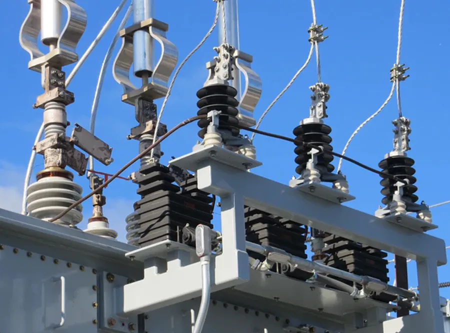
Bushings are critical components in transformers, serving as the insulated interface between the transformer's internal windings and the external electrical network. They ensure safe and reliable transfer of electrical power, preventing current leakage and flashovers by providing a robust and insulated pathway through the transformer tank.
These components are designed to withstand high voltages and currents while maintaining electrical isolation. The selection of bushing types and materials depends on the voltage level, current rating, and environmental conditions where the transformer is installed.
| Bushing Type | Typical Application | Key Features | Advantages | Disadvantages |
|---|---|---|---|---|
| Solid Bushings | Low to medium voltage transformers | Porcelain or polymer insulator | Cost-effective, simple design | Limited voltage rating |
| Oil-Filled Bushings | Medium to high voltage transformers | Oil-impregnated paper or resin insulator | Good electrical insulation, self-cooling | Requires regular oil monitoring and maintenance |
| Capacitor Bushings | High voltage transformers | Multiple layers of insulated material separated by conductive layers | Superior voltage handling, improved insulation | Complex construction, higher cost |
| Gas-Filled Bushings | Extra high voltage transformers | SF6 or other inert gas as insulator | Excellent insulation, compact size | High cost, requires specialized gas handling procedures |
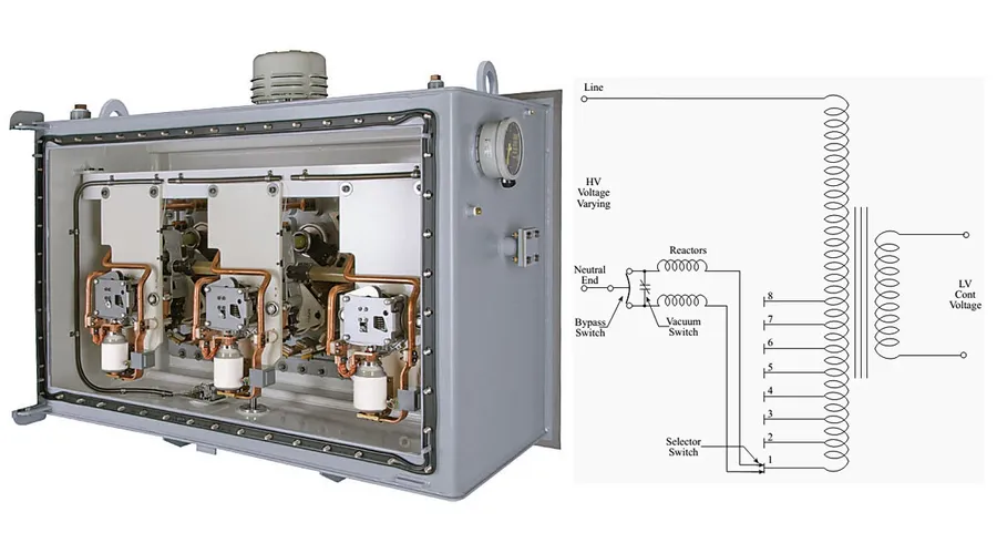
Tap changers are crucial components in transformers, enabling the modification of the turns ratio and, consequently, the output voltage. This adjustment is vital to accommodate fluctuations in load conditions and maintain a stable power supply. Tap changers allow for precise voltage control, ensuring that connected equipment receives the intended voltage despite variations in the incoming line voltage or the load demand.
Two primary types of tap changers exist: on-load and off-load. On-load tap changers (OLTCs) allow adjustments while the transformer is energized, making them essential in dynamic operating environments where continuous power supply is a priority. Off-load tap changers, conversely, require the transformer to be de-energized before adjustments can be made. This distinction significantly impacts their applications and operational procedures.
| Feature | On-Load Tap Changer (OLTC) | Off-Load Tap Changer |
|---|---|---|
| Adjustment Capability | Adjustments can be made while the transformer is energized | Requires the transformer to be de-energized for adjustments |
| Application | Used in dynamic environments with varying loads | Suitable for systems where load adjustments are infrequent or downtime is acceptable |
| Complexity | More complex design with additional mechanical and electrical components | Simpler design with fewer components |
| Cost | Higher cost due to increased complexity and materials | Lower cost due to simpler design |
| Operation | Provides seamless and instantaneous voltage adjustment | Requires a complete shut down of the system to adjust voltage |
The mechanism of a tap changer involves moving a contact arm or a selector switch along the transformer winding taps. Each tap represents a different number of turns in the winding, therefore altering the turns ratio between primary and secondary windings. In OLTCs, this process is carefully controlled to minimize voltage fluctuations during switching, often employing make-before-break switching techniques or reactors to limit transient currents. Off-load tap changers, due to their stationary operation during circuit energization, employ simpler mechanical contact mechanisms.
Transformer oil is a critical component, serving a dual purpose: providing essential electrical insulation and acting as a coolant to dissipate heat generated during transformer operation. Its properties are carefully engineered to ensure reliable performance and longevity of the transformer.
| Property | Description | Significance |
|---|---|---|
| Dielectric Strength | Ability to withstand electrical stress without breaking down. | Ensures reliable insulation, preventing short circuits between windings. |
| Flash Point | The lowest temperature at which the oil's vapor can ignite. | Critical safety parameter; higher flash point improves safety. |
| Viscosity | The oil's resistance to flow. | Affects the oil's cooling and heat dissipation efficiency. Optimal viscosity ensures proper circulation. |
| Moisture Content | Amount of water present in the oil. | Excessive moisture reduces dielectric strength and can cause corrosion. |
| Oxidation Stability | Resistance to chemical degradation due to oxygen exposure. | Maintains oil quality, preventing sludge formation and acid development. |
| Specific Heat Capacity | Ability to absorb heat without a large temperature increase. | Crucial for cooling; a higher capacity allows the oil to absorb more heat. |
Regular testing and maintenance of transformer oil are crucial to ensure its effectiveness. Tests include: measurement of dielectric strength to ensure insulation capacity, moisture content analysis to prevent degradation, and oxidation stability tests to ascertain remaining life. Maintenance practices involve oil filtration and replacement, as needed, to maintain its properties within specified limits.
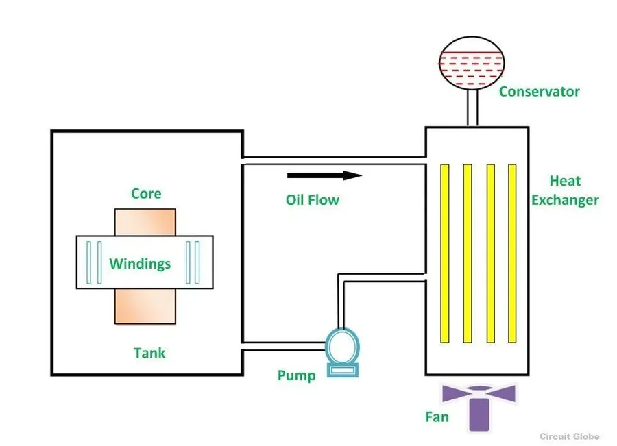
Transformer cooling systems are crucial for maintaining operational temperature and preventing failures by dissipating the heat generated during energy conversion. Effective cooling prolongs the life of the transformer, ensures stable performance, and reduces the risk of thermal breakdown.
| Cooling Method | Description | Advantages | Disadvantages |
|---|---|---|---|
| Oil-Filled Radiators (ONAN) | Natural oil circulation with radiators dissipating heat to the surrounding air. | Simple, reliable, cost-effective for smaller transformers. | Limited cooling capacity, less efficient for high heat loads. |
| Air Cooling (AN) | Heat dissipated directly into the surrounding air. | Very simple and requires no auxiliary equipment. | Limited cooling capacity, not suitable for high-power transformers. |
| Forced Oil Cooling (ONAF/OFAF) | Oil is circulated by pumps, and heat is dissipated through radiators with fans. | Higher cooling capacity than natural cooling, suitable for medium-sized transformers. | More complex system, higher initial and maintenance costs. |
| Oil-Water Cooling (OW) | Oil circulates through a heat exchanger which is cooled by water | Very high cooling capacity, efficient for large transformers. | Requires a reliable source of cooling water and more complex maintenance. |
| Forced Oil and Forced Air Cooling (OFAF) | Both oil and air are circulated with fans and pumps. | Provides the highest cooling capacity, suitable for very large transformers | Most complex and expensive cooling method. |
The selection of an appropriate cooling method depends on the transformer's size, load requirements, ambient temperature, and economic considerations. Regular maintenance and monitoring of cooling systems are essential to ensure optimal transformer performance and longevity.
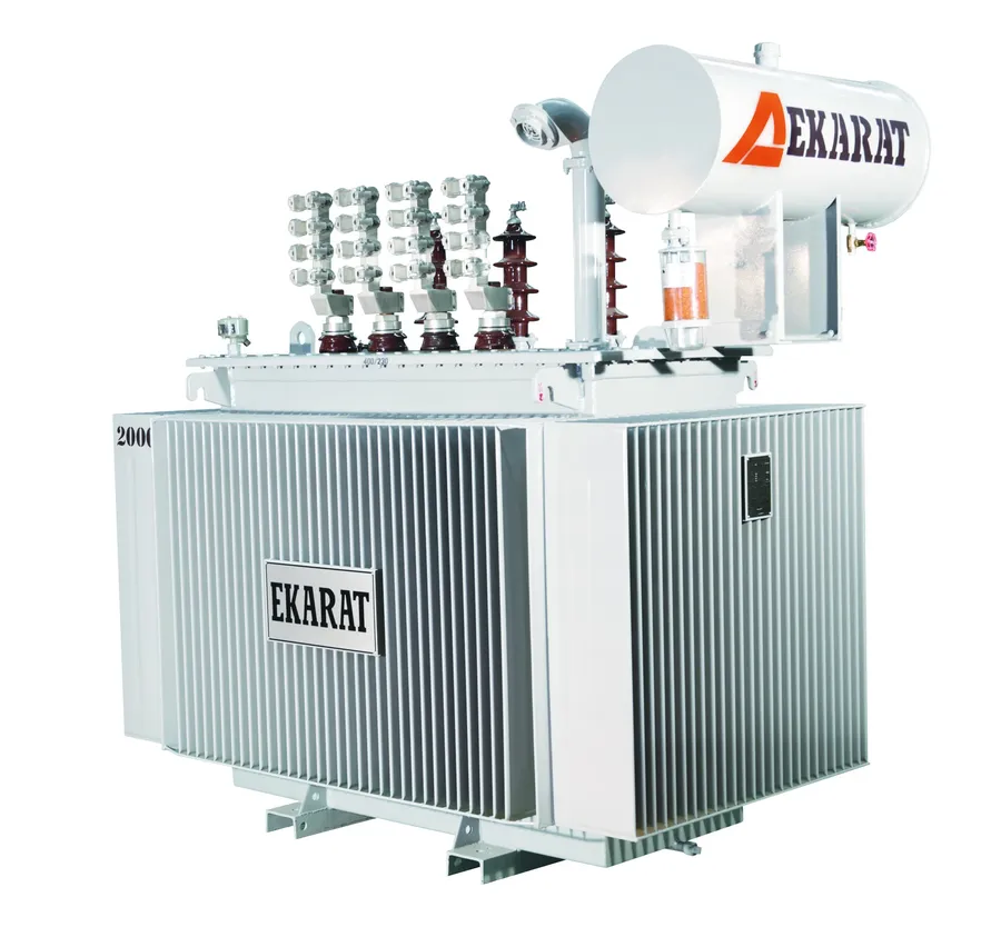
The conservator tank, an essential component of oil-filled transformers, is specifically designed to accommodate the volumetric variations of the transformer oil caused by thermal expansion and contraction during operation, which significantly contributes to the transformer's overall reliability and longevity.
The conservator tank is typically a cylindrical or rectangular vessel positioned above the main transformer tank. It is partially filled with transformer oil and connected to the main tank through a pipe. As the transformer heats up during operation, the oil expands, and this excess volume flows into the conservator tank. Conversely, when the transformer cools down, the oil contracts, and the oil flows back from the conservator into the main tank. This process prevents the buildup of excessive pressure within the transformer and avoids the formation of a vacuum, both of which can be detrimental to the system's integrity.
The long-term operational efficiency of a transformer is directly affected by the proper functioning of the conservator tank. Without a well-designed conservator, pressure variations could lead to damage of the transformer tank and internal components. Regular inspections of the conservator tank include checking oil levels, oil condition, and ensuring that the breather device is functioning correctly.
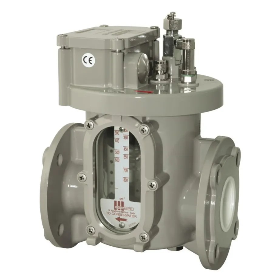
The Buchholz relay is a critical safety device installed in oil-filled transformers, designed to detect and respond to internal faults before they escalate into major failures. Its primary function is to protect the transformer from damage caused by conditions like gas accumulation, sudden oil level drops, or excessive pressure build-up. By triggering alarms or tripping the circuit breaker, it prevents more serious damage and costly repairs.
The Buchholz relay operates based on the principle of gas accumulation and sudden pressure changes within the transformer. It's typically installed in the piping between the transformer tank and the conservator tank. Various internal faults within the transformer can produce gas, causing the oil level within the relay to decrease, thus triggering a float switch or mercury switch. In addition, a sudden pressure wave caused by a fault can also be detected by a flap within the relay, triggering a different alarm or trip.
| Feature | Description |
|---|---|
| Location | Piping between transformer tank and conservator tank |
| Principle of Operation | Gas accumulation and sudden pressure changes |
| Primary Function | Detection of internal faults (e.g., gas build-up, oil leaks) |
| Alarm Trigger | Small gas accumulation or slow oil level drop |
| Trip Trigger | Large gas accumulation, rapid oil level drop, or sudden pressure surge |
| Protection mechanism | Prevents severe damage, protects windings and core |
The relay includes two alarm stages, corresponding to different severities of internal fault. The first alarm stage triggers when a small amount of gas accumulates, indicating a minor fault. The second alarm stage, a trip stage, is triggered by rapid gas production or a sudden pressure surge, indicating a severe fault. This level of sensitivity and discrimination provides effective protection against a range of internal failure modes.
This section addresses common questions regarding transformer components, their functions, and maintenance. Understanding these aspects is crucial for effective operation and longevity of transformers.
Transformers are intricate machines with numerous essential components working in concert to ensure reliable and efficient power distribution. Understanding these parts, from the core and windings to the protective devices like the Buchholz relay, allows for better maintenance, troubleshooting, and operation. This comprehensive knowledge not only helps ensure the longevity of the equipment but also highlights the importance of each component in maintaining the stability of the entire power grid.

