Just like a team of rowers contributing to the boat's overall speed, resistors in series contribute to the total resistance of a circuit. This article demystifies how resistors connected in series impact current flow and voltage, providing a foundational understanding for anyone working with electronics. We'll explore the core principles, calculations, and real-world implications, allowing you to optimize your circuits effectively.
Understanding Series Circuits: The Basics
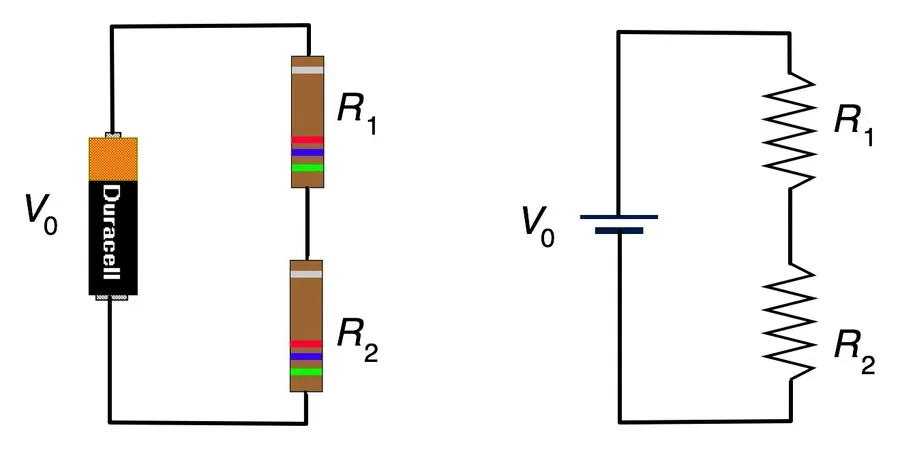
Series Resistor Circuit Diagram
A series circuit is characterized by a single path for electrical current, where components, such as resistors, are connected end-to-end, forming a closed loop. This arrangement dictates that the current flowing through each resistor in the series is identical, a fundamental principle of series circuits.
In a series circuit, the flow of current must pass sequentially through each component. If any point in the circuit is interrupted, the flow of current ceases throughout the entire circuit. This principle contrasts with parallel circuits, where the current has multiple pathways. Each resistor in a series circuit plays a role in establishing the total resistance and in distributing the voltage according to its individual resistance.
Calculating Equivalent Resistance in Series
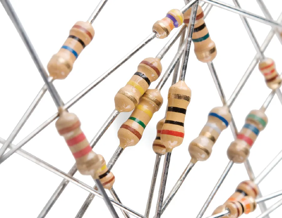
Various Electronic Resistors
In a series circuit, the total or equivalent resistance is the sum of all individual resistances. This fundamental principle dictates that the overall opposition to current flow increases with each additional resistor added in series. This is because the current has to pass through each resistor sequentially, and each resistor contributes to the total impedance.
The formula for calculating the equivalent resistance (R_total) of resistors connected in series is given by:
R_{total} = R_1 + R_2 + R_3 + ... + R_n
Where R₁, R₂, R₃, ..., R_n represent the resistance values of each individual resistor in the series. This formula simply adds each resistance value to find the total resistance. The key is that all resistors must be in the same series path in order for this formula to be accurate.
Let’s look at a few examples to illustrate this principle:
Example
Resistors in Series
Calculation
Equivalent Resistance (Rtotal)
Example 1
R1 = 10 Ω, R2 = 20 Ω
Rtotal = 10 Ω + 20 Ω
30 Ω
Example 2
R1 = 100 Ω, R2 = 200 Ω, R3 = 300 Ω
Rtotal = 100 Ω + 200 Ω + 300 Ω
600 Ω
Example 3
R1 = 100 Ω, R2 = 100 Ω, R3 = 100 Ω, R4 = 100 Ω
Rtotal = 100 Ω + 100 Ω + 100 Ω + 100 Ω
400 Ω
These examples demonstrate that when resistors are connected in series, their resistances simply add up. This is the key concept: the equivalent resistance in a series circuit is always greater than the value of any single resistor within that circuit. This understanding is crucial for designing and analyzing electronic circuits.
Current Flow in a Series Circuit
Resistors on Breadboard
In a series circuit, the current is uniform throughout, meaning that the same amount of current flows through each resistor, regardless of its individual resistance value. This fundamental characteristic arises from the single path that the current is constrained to follow within a series configuration. The magnitude of this current is dictated by the voltage source and the total equivalent resistance of the series combination, as defined by Ohm's Law.
To illustrate this concept, consider a simple series circuit comprising a voltage source (V) and three resistors, R1, R2, and R3. The current (I) circulating in this circuit is determined by the total resistance (Rtotal = R1 + R2 + R3) and the applied voltage (V), according to Ohm’s Law (I = V / Rtotal). The key point is that the value of the current I is exactly the same as it flows through R1, then R2, and then R3, and so on.
The total current in the circuit is determined by Ohm's Law (I = V/R), where 'V' is the supply voltage and 'R' is the equivalent resistance (Rtotal) of all series resistors. This principle demonstrates how each resistor contributes to the overall impedance of the circuit, thereby governing the current flow through the entire series path.
Voltage Division in Series Circuits
Multimeter Measuring Voltage
In a series circuit, the total applied voltage is not distributed evenly across all resistors; instead, it is divided proportionally based on each resistor's ohmic value. This phenomenon, known as voltage division, is a direct consequence of Ohm's Law, where voltage is a product of current and resistance. Since the current is uniform throughout a series circuit, the voltage drop across a resistor is directly proportional to its resistance. A larger resistance will experience a larger voltage drop than a smaller resistance, as the current must 'expend' more electrical potential to overcome the impedance it poses.
This principle allows for the creation of voltage dividers, where a higher voltage can be reduced to a smaller, more useful voltage for specific components.
The voltage drop across any resistor (V_R) in a series circuit can be calculated using the voltage divider formula: V_R = (R / R_total) * V_total. Where V_R is the voltage across the specific resistor, R is the resistance of the specific resistor, R_total is the total series resistance, and V_total is the applied voltage across the series combination.
Practical Applications of Resistors in Series
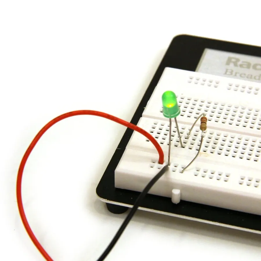
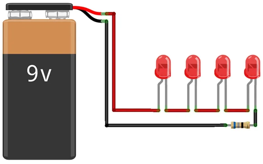
LEDs in Series with Resistors
Series resistors are fundamental components in numerous real-world applications, providing essential functionalities such as voltage division, current limiting, and circuit protection. Their simple yet powerful behavior makes them indispensable in both basic and complex electronic designs.
Voltage Dividers Series resistor configurations act as voltage dividers, a crucial technique for creating intermediate voltages from a single source. This is often used in sensor circuits for calibration or to provide bias voltages to operational amplifiers and other components.
LED Current Limiting A common application of series resistors is to limit current flowing through Light Emitting Diodes (LEDs). Since LEDs have a non-linear current-voltage relationship, a series resistor is critical to prevent damage from excessive current flow. The resistor value is calculated based on the LED's forward voltage drop and desired operating current, ensuring the LED operates within safe parameters.
Sensor Calibration In sensor circuits, series resistors can be used to calibrate sensor readings. They allow for precise scaling of the sensor's output to match the input requirements of data acquisition systems or microcontrollers. This is particularly useful when a sensor's raw output isn't directly compatible with the measurement circuit.
Protection of Sensitive Components Series resistors act as protective barriers in circuits, limiting the current flow and reducing the likelihood of damage to sensitive components such as ICs, transistors, and microcontrollers. They serve as a fail-safe in situations where a fault might otherwise cause a component to overload.
Simple Electronic Projects In many simple electronic projects, series resistors play a role in ensuring correct circuit function. Whether it is adjusting the brightness of an LED, creating a specific voltage reference for a comparator, or setting a timing constant with an RC network, resistors in series are necessary for achieving the desired outcome.
How to Identify Resistors in Series vs. Parallel
PCB with series and parallel components
Distinguishing between series and parallel resistor configurations is crucial for accurate circuit analysis. The key difference lies in how current flows through the circuit. In a series circuit, current has only one path, whereas in a parallel circuit, current has multiple paths to follow.
Visual Cues for Series Circuits Resistors in series are connected end-to-end, forming a single continuous path. Visually, they appear as a chain, with the output of one resistor directly feeding into the input of the next. The current flows sequentially through each resistor in the chain.
Visual Cues for Parallel Circuits Resistors in parallel have their inputs connected together at one point and their outputs connected together at another point, creating branching paths for current flow. Visually, they appear as multiple 'legs' connected to two common nodes. Current splits and travels along these multiple paths.
Current Path Analysis To determine the circuit type, trace a path through the circuit. If the current has only one possible route through all resistors, they are in series. If the current can split and take different paths through different resistors, then they are in parallel. Any given resistor will only be part of the series or part of the parallel configuration, never both.
Frequently Asked Questions About Series Resistors
Understanding the nuances of series resistors is crucial for effective circuit design and troubleshooting. Below are some frequently asked questions addressing common concerns and practical scenarios related to series resistor circuits.
What happens to the current when you add more resistors in series? Adding more resistors in series increases the total resistance of the circuit. According to Ohm's Law (I = V/R), if the voltage source remains constant, an increase in resistance will cause a decrease in the total current flowing through the series circuit. The current is the same at all points in a series circuit.
How do temperature changes affect resistors in a series circuit? The resistance of most materials changes with temperature. Typically, for standard resistors, an increase in temperature will lead to an increase in their resistance. In a series circuit, the temperature coefficient of each resistor will individually affect the overall circuit resistance. If temperature increases, each resistor will have a larger resistance, and thus the total series resistance will increase. It's important to consider these effects in thermal conditions, where resistors with poor temperature coefficients can dramatically change circuit behavior.
How do I select the correct resistor values for my series circuit application? Selecting the correct resistor values involves careful consideration of your circuit requirements, using Ohm's Law. First, determine the voltage and current requirements of your application (e.g., the desired voltage drop across a resistor, the current needed in an LED circuit). Then, using Ohm’s Law (R=V/I), calculate the required resistance value. You need to choose resistors with power ratings adequate to handle the expected power dissipation in the circuit. Always choose a resistor rating higher than your calculation to provide a safety margin. For precise applications, also be mindful of resistor tolerances.
How do tolerances of resistors affect a series circuit? Resistor tolerances specify the allowable variance from the marked resistance value. In a series circuit, the total resistance is the sum of individual resistances, so the tolerance of each resistor contributes to the total resistance tolerance. For example, if you have two 100 Ohm resistors, each with a 5% tolerance in series, the total series resistance would be ideally 200 Ohm, but its tolerance would also compound to some extent, possibly ranging from 190 to 210 ohm, which is a non negligible tolerance of the result. For precision applications, it’s critical to understand how tolerances add up and to possibly use more precise resistors to avoid issues.
How can you determine if a set of resistors are in series or parallel when looking at a circuit diagram? In a series configuration, resistors are connected end-to-end, forming a single path for current flow. You will see that the current flows through one resistor, then the next, and so on. In a parallel circuit, resistors are connected side by side, creating multiple paths for current flow. If the current has multiple paths to go through, and splits and rejoins later, it’s a parallel connection. If a line traces through a resistor, and then immediately into another resistor, then this would be a series connection.
Can you have a mixed series and parallel circuit? Yes, circuits can contain both series and parallel configurations. In such mixed circuits, the behavior is governed by the combination of series and parallel rules. When analysing a mixed circuit, it is often necessary to begin by analysing the component sections of series or parallel connections, and only then proceed with the remaining equivalent resistances.
Troubleshooting Common Series Circuit Issues
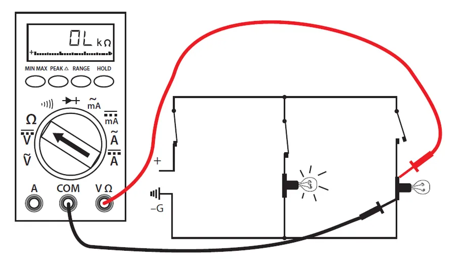
Effective troubleshooting of series circuits involves identifying common failure points such as open resistors or incorrect component values, using techniques such as voltage and resistance measurements with a multimeter to isolate problems and restore circuit functionality.
Open Resistor A resistor that has failed, usually due to excessive current or age, and no longer conducts electricity. Symptoms include a break in the circuit, no current flow, and full supply voltage across the open resistor. Multimeter testing will show infinite resistance.
Incorrect Resistor Value Using a resistor with the wrong resistance rating can alter the intended functionality. The incorrect resistance impacts voltage division, current limiting and can lead to abnormal circuit behavior, such as the circuit working at a lower voltage. Compare the intended value with the labeled value (or the color codes) and test resistance with a multimeter.
Short Circuit While less common in a series circuit between the resistors, it is a serious condition to test for. A short circuit bypasses one or more resistors reducing the overall circuit resistance. Test each wire and each connection point to ensure that the resistances between any point is not too low compared to the intended circuit values.
Loose Connections Poor mechanical contacts result in intermittent or complete lack of conduction. Check all physical connections and ensure that they are clean, well soldered and fully secured to avoid poor current flow. Resolder or retighten as needed to avoid intermittent problems or overheating.
Power Supply Issues The power source may be inadequate in terms of voltage or current, and will affect the entire circuit if it is not providing proper power. Test the power supply output with a multimeter under load (connected to the series circuit) to ensure it delivers the correct voltage and enough current for all components.
To effectively troubleshoot a series circuit, you should perform the following steps:
Visual Inspection Check for any visible signs of damage, such as burnt or broken components, loose connections, or any physical abnormalities with the wiring.
Voltage Measurements With the power applied, use a multimeter to measure the voltage drop across each resistor. In a series circuit, the total voltage should equal the sum of all the individual voltage drops. A lack of voltage across one resistor indicates an open circuit at this location, while a voltage much lower than expected may indicate the resistor value has changed.
Resistance Measurements With the power off, measure the resistance of each resistor using a multimeter to verify the correct value. An open resistor will have infinite resistance and a partially failed resistor may have too high of a resistance compared to the intended value.
Current Measurement Measuring the current flow in a series circuit can be useful for identifying shorts and verifying the operation of your circuit. Insert a multimeter, in current measurement mode, at different points in the series loop. The current should be the same at all points in the loop. Any variations indicate a short circuit.
Isolate the Problem Once a problematic component or area has been identified, you can systematically swap out resistors or repair connections to see if the circuit resumes working as expected. Always disconnect power before making any changes.
Series Resistors vs. Parallel Resistors: A Comparison
Understanding the fundamental differences between series and parallel resistor configurations is crucial for effective circuit design and analysis. This section provides a clear comparison, highlighting the distinctions in current, voltage, resistance calculations, and practical uses for each configuration.
Characteristic
Series Resistors
Parallel Resistors
Current Behavior
Current is the same through all resistors.
Current divides between different paths.
Voltage Behavior
Voltage is divided across resistors based on their resistance.
Voltage is the same across all resistors.
Equivalent Resistance Calculation
Rtotal = R1 + R2 + R3 + ...
1/Rtotal = 1/R1 + 1/R2 + 1/R3 + ...
Practical Applications
Voltage dividers, LED current limiting, simple circuits requiring a reduction in current.
Providing multiple paths for current, complex circuits, maintaining voltage levels across a load.
Total Resistance
The total resistance is always greater than the individual resistors.
The total resistance is always less than the smallest resistor.
Path for Current
Single path for the current to flow.
Multiple paths for the current to flow.
Understanding how resistors work in series is fundamental to mastering electronics. Just as rowers work in unison, resistors in series circuits share a single path for current, which directly affects the equivalent resistance and voltage distribution. This knowledge empowers you to design, analyze, and troubleshoot a wide range of circuits, ensuring your projects function optimally. By mastering the basics outlined in this guide, you will be better equipped to handle more complex electronic systems and designs, opening new possibilities for creativity and innovation.