The Arduino Nano, a compact yet powerful microcontroller board, has become a cornerstone in electronics projects. Understanding the [arduino nano pin layout] is crucial for seamless integration and efficient project execution. This guide will demystify the pin functions, providing practical knowledge to help you utilize the Nano's capabilities for your creations. We'll start by exploring the physical layout, then move on to individual pin descriptions, and finally touch upon potential use cases, to bridge the gap between theory and practical application of this board.
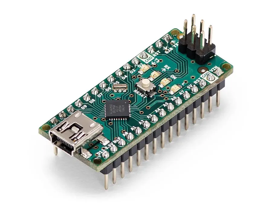
The Arduino Nano, a compact yet powerful microcontroller board, features a dual inline pin arrangement that distinguishes it from its larger counterpart, the Arduino Uno. This compact design is essential for projects where space is a limiting factor. This section will focus on the physical layout, detailing the placement of power, digital, and analog pins, and how this physical arrangement relates to the board's schematic design.
Unlike the Arduino Uno, which utilizes a larger form factor and includes additional features like a dedicated power jack, the Arduino Nano prioritizes a small footprint. This difference in size impacts the pin arrangement and overall design, requiring users to understand how pin locations directly relate to schematic diagrams and project integration.
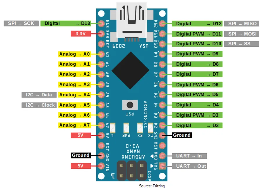
The Arduino Nano's power pins are crucial for supplying and distributing electrical power to the board and any connected components. Understanding these pins—VIN, 5V, 3.3V, and GND—is fundamental for safe and effective operation. The Nano can be powered via the USB connection or through the VIN pin, and it also provides regulated 5V and 3.3V outputs for powering other circuits. Proper use of the ground (GND) pin is essential for establishing a common reference point.
| Pin | Description | Voltage Range/Output | Maximum Current |
|---|---|---|---|
| VIN | Voltage Input | 7-12V (Recommended) | Determined by regulator, input should not exceed 12V. |
| 5V | Regulated 5V Output | 5V | Typically up to 500mA from USB; less when powered by VIN. |
| 3.3V | Regulated 3.3V Output | 3.3V | Typically up to 50mA |
| GND | Ground | 0V | Common reference point for all voltages. |
The VIN pin can accept an unregulated voltage input, which is then regulated down to 5V by the on-board voltage regulator. It is crucial to note that the current that the 5V output can supply will vary depending on the input method, being around 500mA when powered via USB and less when powered via VIN due to the regulators efficiency and limitations. The 3.3V output, on the other hand, is provided by a smaller onboard regulator and its current capability is typically limited to around 50mA. Exceeding these current limits can potentially damage the Nano or the connected components, and therefore careful consideration is required when designing projects. The GND pin is essential for completing circuits, as it provides a common reference point for voltage measurements and current flow.
The Arduino Nano boasts 14 digital input/output (I/O) pins, designated D0 through D13, each capable of operating as either an input or an output. This dual functionality is crucial for interfacing with a wide range of digital components and sensors. These pins are fundamental to controlling external devices, reading digital signals, and implementing logic within your projects. Understanding their capabilities and limitations is essential for effective Arduino Nano utilization.
Each digital pin on the Arduino Nano operates at 5V logic, meaning that a 'HIGH' signal is approximately 5V, and a 'LOW' signal is approximately 0V. These pins are not designed to withstand high currents, typically a maximum of 20mA per pin, with an absolute maximum of 40mA. Exceeding these limits can damage the microcontroller. Furthermore, it is essential to note that the total current sourced or sunk by all pins combined should not exceed the overall limits specified for the ATmega328P microcontroller, which is approximately 200mA.
| Pin Number | Functionality | Additional Notes |
|---|---|---|
| D0 (RX) | Digital I/O, Serial Receive | Used for serial communication, can also function as a general-purpose I/O pin when serial is not in use. |
| D1 (TX) | Digital I/O, Serial Transmit | Used for serial communication, can also function as a general-purpose I/O pin when serial is not in use. |
| D2-D12 | Digital I/O | General-purpose digital input/output pins. Can be used with digital sensors, LEDs, buttons, etc. |
| D3, D5, D6, D9, D10, D11 | Digital I/O, PWM Output | Capable of generating Pulse Width Modulation (PWM) signals for controlling motors, dimming LEDs, and other analog-like behaviors. |
| D13 | Digital I/O, Built-in LED | Connected to the onboard LED. Can be used as a general-purpose I/O pin, but is most commonly used to check the functionality of the Arduino. |
Specifically, digital pins D3, D5, D6, D9, D10, and D11 are also capable of generating Pulse Width Modulation (PWM) signals. PWM allows you to simulate analog output by rapidly switching the pin between HIGH and LOW states, and the duty cycle of this switch determines the effective 'analog' voltage. This is invaluable for tasks requiring variable power delivery or control such as controlling motor speed or dimming LEDs. D0 and D1 are reserved for serial communication, which can be used to send and receive data to or from a computer, or other serial devices. While they can be used as general digital I/O, doing so disables serial communication capability. Therefore, understanding the special function of these pins is critical for project design, specifically, avoiding conflicts when implementing serial functionality.
When utilizing these digital I/O pins, it’s essential to be aware of the current limitations. For example, directly connecting LEDs without appropriate current-limiting resistors can damage the pins or the LEDs. Best practice is to use resistors or driver circuits to control the current flowing to and from the pin, ensuring that the maximum current and voltage ratings of the pins and connected components are never exceeded. Additionally, when using digital pins as inputs, they should not be left unconnected ('floating'), as this can lead to erratic readings. These should be connected either to a defined high or low state, either actively or via pull-up or pull-down resistors as appropriate.
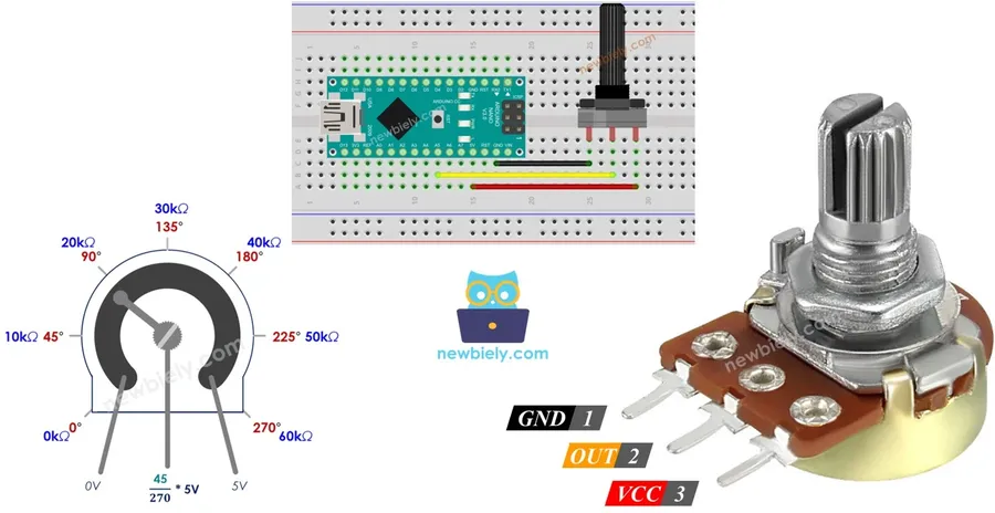
The Arduino Nano features eight analog input pins, designated A0 through A7, which are crucial for interfacing with analog sensors. These pins enable the Nano to measure varying voltage levels, converting them into digital values that the microcontroller can understand and process. This section details the functionality of these pins, their analog-to-digital conversion process, and practical applications with sensors.
Each analog pin on the Arduino Nano connects to an internal Analog-to-Digital Converter (ADC), which transforms incoming analog voltage signals into a corresponding digital value. This allows the Arduino Nano to interface with sensors that produce a continuous voltage range. The ADC on the Nano has a 10-bit resolution, which means that it represents the measured voltage as an integer between 0 and 1023.
| Characteristic | Description |
|---|---|
| Number of Analog Pins | 8 (A0 to A7) |
| ADC Resolution | 10-bit (0-1023) |
| Voltage Range | 0 to 5V (typically) |
| Typical Sensor Types | Temperature, Light, Pressure, Potentiometers, etc. |
The 10-bit resolution provides a precision level of approximately 4.88 mV per unit (5V / 1024). Therefore, an analog signal of 0V at a given analog pin will be read as 0, a 5V signal will be read as 1023, and a 2.5V signal will be read as approximately 512. This conversion allows the Nano to understand the signal and perform calculations based on the analog input. It is crucial to understand the ADC resolution to accurately interpret the input from sensors.
When using analog pins, ensure that the voltage applied does not exceed the operating limits of the Arduino Nano (typically 5V) to avoid damage. Most sensors are designed to work within this range. For best results, the sensor's output voltage range should be appropriately scaled to match the input range of the ADC. The usage of voltage dividers or operational amplifiers may be required for some sensors if their output voltage is outside the 0-5V range.
In practical terms, these analog input pins are used to connect various sensors such as temperature sensors, light sensors (e.g., photoresistors), pressure sensors, or potentiometers, allowing the Arduino to interact with its environment and take accurate measurements.
To use the analog input pins, the `analogRead()` function is used within the Arduino code. This function takes the pin number as an argument, and returns the digital value resulting from the ADC conversion. This value must then be scaled appropriately for use in the program, depending on the sensor being used. For example, if connecting a temperature sensor, a calibration or linear conversion factor may be required to convert the read digital value into a temperature reading.
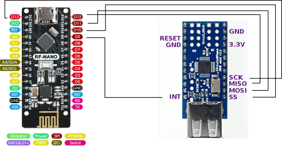
Beyond the standard power, digital, and analog pins, the Arduino Nano incorporates specialized pins that enable advanced functionalities. These pins, namely AREF, Reset (RST), and the I2C communication pins (SDA/SCL), are crucial for more sophisticated projects requiring analog reference adjustments, microcontroller resets, and communication with I2C peripherals.
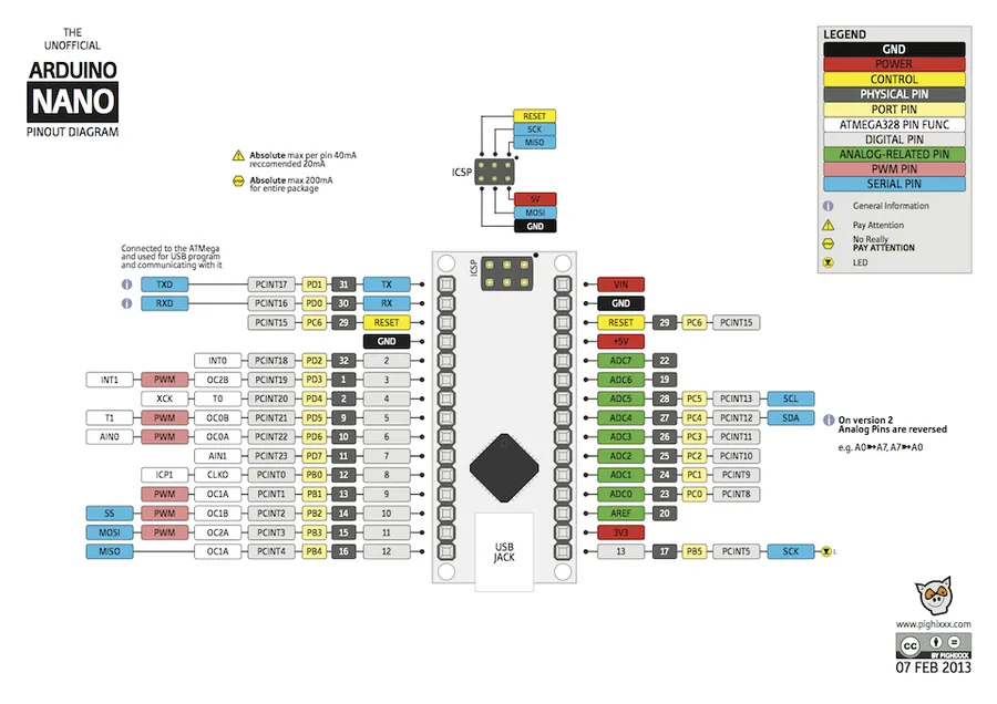
Pin layout diagrams are essential for effectively using the Arduino Nano, acting as visual roadmaps that detail the function and location of each pin. These diagrams are available in schematic and visual forms and are crucial for identifying pins, connecting peripherals, and planning projects. By comprehending these layouts, users can ensure correct component connections and avoid damaging the board.
Pinout diagrams for the Arduino Nano typically consist of two primary types: schematic diagrams and visual pinout diagrams. Schematic diagrams represent the electrical connections, whereas visual diagrams show the physical location of each pin on the board. Understanding how these two relate provides a comprehensive understanding of the board’s functionality.
Key elements to look for in a pinout diagram include: Pin Names and Numbers, Functionality, and Alternate functions. Every pin is labeled with a name and/or number (e.g., D0, A5), these labels correspond directly to the pins on the physical board. The diagram also indicates whether a pin is a power pin (e.g. VCC, GND), a digital I/O pin (D0-D13) , an analog input pin(A0-A7) or a special function pin. Note that some pins have alternate functionalities (e.g. digital pins with PWM capabilities).
When using pinout diagrams, it is important to cross reference both the schematic view for electrical relationships, and the visual view for physical placement on the board. This is important for effective component placement and wiring. Ensure that the diagrams you use accurately represent the specific version of the Arduino Nano you are working with, as minor variations may occur across different revisions. With an understanding of these diagrams, users can more effectively design and implement their Arduino-based projects, ensuring both functionality and safety. Using pinout diagrams accurately minimizes wiring errors and ensures circuits operate as designed.
Understanding the limitations of the Arduino Nano's pins is crucial for preventing damage to the board and ensuring the reliable operation of connected components. This section outlines these limitations and provides best practices for safe and effective use.
The Arduino Nano, while versatile, has specific operational constraints that users should be aware of:
Best Practices for Safe Operation:
By understanding these limitations and adopting the recommended best practices, users can prevent damage to their Arduino Nano boards and ensure reliable and accurate operation. Following these guidelines provides a robust platform for project development.
This section addresses common questions about the Arduino Nano's pin layout, drawing from related searches like 'Arduino Nano schematic,' 'Arduino Nano datasheet,' 'Arduino Nano pin numbers,' 'Arduino Nano PWM pins,' and 'Arduino Nano I2C pins'. It serves as a quick reference for key information discussed throughout this guide.
Understanding the [arduino nano pin layout] is paramount for harnessing the full potential of this versatile microcontroller. This guide has covered the pin functions, including digital, analog, power, and special function pins, and has explored layout considerations to equip you with the necessary skills to execute your projects effectively. Remember that attention to pin limitations, careful wiring, and accurate referencing of the pin layout diagrams will always contribute to success in your endeavors. With this knowledge, you're now better prepared to confidently dive into your next Arduino Nano-based projects.

