
In the remote landscapes where wind energy thrives, the cost of failure is high. Every minute a turbine stops spinning due to electronic fault is a direct hit to your bottom line. This article explores why superior PCB interconnect integrity is the unsung hero of renewable infrastructure, turning chronic maintenance burdens into models of long-term reliability.
The Hidden Cost of Standard Electronics in Renewable Energy
The Vulnerability of Consumer-Grade Electronics in Wind Environments
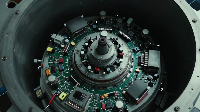
Wind turbine nacelles represent one of the most hostile operating environments for sensitive electronic components. While standard, consumer-grade Printed Circuit Boards (PCBs) are sufficient for climate-controlled office settings, they lack the structural integrity and material specifications required to withstand the high-amplitude vibrations and aggressive thermal cycling present at hub heights. When standard PCBs are deployed in these conditions, solder joints experience fatigue, micro-cracks propagate through substrate materials, and thermal expansion mismatches between components lead to critical interconnect failure.
Comparative Durability: Standard vs. Industrial-Grade PCBs
| Failure Driver | Standard PCB Response | Robust Design Mitigation |
|---|---|---|
| Thermal Cycling | Coefficient mismatch causes solder fatigue | High-Tg materials and thermal relief pads |
| Mechanical Vibration | Component delamination and cracked traces | Conformal coating and reinforced mechanical anchors |
| Moisture/Condensation | Corrosive oxidation of exposed copper | Industrial-grade epoxy encapsulation |
The Economic Impact of Early Component Failure
The hidden cost of utilizing non-hardened electronics is not merely the replacement price of the board itself. The true fiscal drain originates from the 'maintenance multiplier' associated with wind turbine assets. Each failure event necessitates specialized crane deployment, skilled technician mobilization, and significant turbine downtime, effectively turning a low-cost electronic component into a multi-thousand dollar operational liability.
- Why do standard PCBs fail specifically in nacelles?
The combination of constant harmonic vibration and extreme temperature swings causes brittle fatigue in standard solder alloys, leading to intermittent connectivity issues that are notoriously difficult to diagnose. - How does robust design affect long-term ROI?
Investing in robust PCB design initially increases capital expenditure by 15-20%, but it drastically reduces the Net Present Value (NPV) of maintenance costs by extending the mean time between failures (MTBF) by several years. - What is the primary indicator of failing electronics?
Increasing signal noise or intermittent data packet loss in the control system is often the first symptom of microscopic damage to PCB traces before a complete catastrophic shutdown occurs.
Engineering for Reliability: The Role of PCB Interconnects
The Engineering Challenge of Nacelle Connectivity
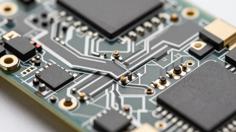
In the harsh environment of a wind turbine nacelle, the PCB interconnect serves as the primary point of failure for control electronics. Continuous vibration, coupled with rapid thermal cycling from start-stop operation, imposes mechanical strain on solder joints and connectors. Robust interconnect design is not merely about signal integrity; it is a critical strategy to prevent micro-cracking and intermittent signal loss that ultimately lead to costly, premature component replacement.
Mitigating Stress via Advanced Interconnect Material Selection
| Interconnect Strategy | Reliability Benefit | Maintenance Impact |
|---|---|---|
| Compliant Pin Technology | Absorbs board flexure without stressing PTH | Eliminates solder joint fatigue |
| High-Tg Laminates | Prevents Z-axis expansion under thermal shock | Reduces via barrel cracking |
| Conformal Coating | Protects joints from moisture and oxidation | Extends operational lifespan |
FAQs on PCB Reliability and Maintenance
- How do vibration levels in turbines impact standard solder joints?
Constant vibration causes cyclical stress on brittle solder alloys, leading to work-hardening and eventual micro-fractures, which manifest as intermittent electrical signals. - Why is Z-axis expansion a primary concern for wind energy PCBs?
Repeated temperature shifts cause the PCB substrate to expand at a different rate than the copper vias, creating mechanical tension that can lead to copper barrel failure. - Can robust design negate the need for periodic manual inspection?
While it does not eliminate the need for maintenance, robust interconnects significantly extend the Mean Time Between Failures (MTBF), allowing for longer maintenance intervals and lower O&M costs.
Case Study: Extending Service Life in Offshore Deployments

Case Study: Extending Service Life in Offshore Deployments
In a recent offshore wind farm deployment located in the North Sea, operational data revealed that frequent turbine downtime was primarily driven by premature electronic failure within the pitch control systems. By replacing standard commercial-grade PCBs with high-reliability, ruggedized circuit assemblies designed for extreme thermal cycling and salt-mist exposure, the project operator achieved a significant reduction in O&M costs.
Performance Comparison: Standard vs. Ruggedized PCBs
| Metric | Standard PCBs | Ruggedized PCBs |
|---|---|---|
| Failure Rate (Annual) | 12% | 2% |
| Field Tech Visits | High Frequency | 40% Reduction |
| Mean Time Between Failures | 2.5 Years | 7+ Years |
Key Lessons from the Offshore Implementation
- Why did standard components fail so frequently?
Standard PCB solder joints experienced micro-fractures due to the intense vibrations and high-amplitude thermal swings inherent in nacelle environments, leading to intermittent signal loss. - What specific design changes drove the 40% reduction?
The transition to high-Tg (glass transition temperature) laminates, enhanced conformal coating, and upgraded interconnect metallurgy prevented moisture-induced corrosion and mechanical fatigue. - How does this translate to long-term profitability?
By decreasing the frequency of offshore crane vessel deployments—which are extremely costly to schedule and execute—the asset owner recouped the initial premium on ruggedized electronics within the first 18 months of operation.
Material Science and Vibration Resistance
Material Science and Vibration Resistance
In the high-vibration environment of a wind turbine nacelle, the physical integrity of a PCB is dictated by the synergy between its substrate material and interconnect metallurgy. Standard glass-reinforced epoxy laminates often succumb to delamination under continuous oscillation; therefore, integrating high-Tg (glass transition temperature) substrates and vibration-resistant solder alloys is critical to maintaining electrical connectivity over decades of operation.
Substrate Selection for Mechanical Durability
Choosing the correct substrate material is the first line of defense against structural fatigue. Engineers should prioritize materials with a low Coefficient of Thermal Expansion (CTE) to ensure the board expands and contracts in harmony with copper traces, minimizing the mechanical strain that leads to micro-cracking.
| Material Property | Standard FR-4 | High-Performance Polyimide |
|---|---|---|
| Glass Transition (Tg) | 130-140°C | 250°C+ |
| Vibration Fatigue | Moderate | Excellent |
| CTE Z-Axis | High (Stress prone) | Low (Stable) |
Advanced Solder Metallurgy
Standard tin-lead or SAC305 solder joints are inherently brittle and prone to fracture under high-frequency vibration. Implementing creep-resistant alloys—specifically those doped with Bismuth or Antimony—improves the ductility of the joint, allowing it to absorb mechanical shocks without forming crystalline fractures that lead to intermittent signal failures.
- Why does CTE matching matter?
Matching the CTE of the PCB material to the components prevents differential expansion during thermal cycling, which is the primary cause of solder joint shear. - Can conformal coating improve vibration resistance?
Yes, high-modulus conformal coatings act as a dampening layer, effectively securing tall or heavy components and distributing mechanical loads across a larger surface area. - Is lead-free solder viable for wind turbines?
While RoHS compliance is standard, specialized high-reliability lead-free alloys must be selected to avoid the brittleness associated with standard SAC-based assemblies.
Calculating the ROI of High-Reliability Components
The Economic Imperative of Upfront Investment
The return on investment (ROI) for high-reliability PCBs in wind energy is driven by the disproportionate cost of unscheduled maintenance. While high-grade capacitors, industrial-rated ICs, and advanced interconnects carry a price premium of 15% to 30% compared to standard components, this initial expenditure is quickly recouped by avoiding the logistical nightmare of turbine downtime. In offshore or remote onshore environments, the cost of a single technician dispatch, including specialized vessel rental or crane deployment, can exceed $20,000—a figure that often dwarfs the entire BOM cost of the control assembly.
| Metric | Standard Grade Component | High-Reliability Component |
|---|---|---|
| Estimated Failure Rate (10 years) | 8-12% | <1% |
| Average Repair Cost per Incident | $15,000 - $25,000 | $15,000 - $25,000 |
| Total Lifetime O&M Impact | High Cumulative Risk | Minimal Operational Disruption |
Modeling 20-Year Operational Savings
To calculate the net benefit, engineers must apply the Total Cost of Ownership (TCO) model. By extending the Mean Time Between Failures (MTBF) through robust PCB design, operators effectively eliminate the secondary costs associated with energy production loss during downtime. For a utility-scale wind farm, avoiding just two unscheduled outages per turbine over a 20-year asset life justifies the adoption of premium components, even before accounting for the extended lifespan of the turbine power electronics.
ROI Calculation FAQs
- How does PCB reliability impact the internal rate of return?
Higher reliability ensures consistent energy yield. By reducing downtime, the revenue stream remains uninterrupted, stabilizing the project's internal rate of return (IRR) against the volatility of O&M spending. - Is there a point of diminishing returns?
Yes. Beyond mission-critical control modules, over-engineering auxiliary display components yields minimal ROI. Focus premium budget allocations on components governing turbine pitch, yaw control, and power conversion. - How do logistics affect the ROI calculation?
Logistics are the primary multiplier. In remote wind projects, the labor-to-part ratio is high; therefore, investing in a part that lasts 5 years longer than standard alternatives provides exponential savings on labor logistics.
Mitigating the Challenges of Remote Accessibility

Designing for Remote Operational Resilience
When wind turbines are deployed in geographically isolated or high-altitude locations, the cost of dispatching maintenance crews often exceeds the replacement cost of the hardware itself. Robust PCB design shifts the paradigm from reactive repair to autonomous longevity by focusing on failure prevention through advanced thermal management, conformal coatings, and redundant signal processing paths.
Maintenance Strategy Comparison
| Strategy | PCB Focus | Accessibility Impact |
|---|---|---|
| Standard Design | Off-the-shelf components | Frequent technician dispatches |
| Ruggedized Design | AEC-Q200 compliant parts | Scheduled bi-annual inspection |
| Autonomous-Ready | Embedded diagnostics & self-healing | Condition-based maintenance only |
Common Challenges in Remote Site Maintenance
- How does PCB component selection mitigate logistical delays?
Utilizing industrial-grade, long-lifecycle components reduces the probability of premature board failure, ensuring that the mean time between failures (MTBF) exceeds the maintenance cycle by a significant margin. - Why is firmware-level diagnostics critical for remote sites?
Robust boards equipped with onboard sensors allow for remote telemetry, enabling operators to differentiate between transient environmental issues and permanent hardware damage, preventing unnecessary site visits. - Can modular PCB design simplify remote repairs?
Yes, designing control systems with hot-swappable, modular sub-assemblies allows field technicians with minimal specialized training to perform rapid replacements without requiring complete system decommissioning.
Implementation Protocol
1. Deploy redundant power rails to isolate fault points.
2. Apply MIL-SPEC conformal coating to mitigate atmospheric corrosion.
3. Integrate remote heartbeat monitoring for real-time health status.
4. Design for modular extraction to reduce mean time to repair (MTTR).
Compliance and Quality Standards for Renewable Electronics
Navigating Industry Compliance for Harsh Environments
In the wind energy sector, electronic assemblies are subject to extreme temperature fluctuations, high humidity, salt spray, and constant mechanical vibration. Compliance with international standards is not merely regulatory; it acts as a risk-mitigation framework. By specifying components and assembly processes that meet IEC 61400 (Wind Turbines) and IPC-A-610 (Acceptability of Electronic Assemblies) Class 3 standards, design teams ensure that PCBs can maintain operational integrity over a 20-year asset life cycle.
Critical Standards for Wind Energy Electronics
| Standard | Relevance to Wind Energy | Operational Benefit |
|---|---|---|
| IPC-A-610 Class 3 | Highest reliability requirements | Ensures performance in mission-critical environments |
| IEC 61400-1 | Wind turbine design requirements | Guarantees structural and electrical safety in extreme wind conditions |
| ISO 9001 | Quality management systems | Provides consistent manufacturing processes and traceability |
Quality Assurance and Maintenance Impact
Quality standards directly translate into reduced maintenance costs by minimizing premature field failures. Rigorous testing protocols—including Highly Accelerated Life Testing (HALT) and thermal cycling—allow designers to identify and rectify latent defects before deployment. When hardware adheres to strict design for reliability (DfR) standards, the frequency of unplanned site visits drops significantly, directly impacting the bottom line for remote offshore and onshore wind farms.
- Why is Class 3 classification essential for wind electronics?
Class 3 covers products where continued high performance or demand-performance is critical, equipment downtime cannot be tolerated, and the end-use environment may be exceptionally harsh. - How does compliance reduce long-term O&M costs?
Compliance with design standards reduces infant mortality and mid-life failure rates of PCBs, decreasing the need for costly field repairs and component replacements in remote turbine locations. - What role does documentation play in maintenance?
Full traceability and quality documentation facilitate predictive maintenance, allowing operators to understand the wear profile of individual components and plan replacements before failure occurs.
Future-Proofing Your Energy Portfolio
Designing for Technological Obsolescence
The operational lifespan of a wind turbine often spans two decades, while industrial electronics typically iterate on a five-year cycle. To prevent premature asset obsolescence, architects must prioritize modular PCB design architectures that allow for component upgrades without replacing entire control systems. By decoupling sensor interfaces from main processing logic, operators can swap out outdated communication modules or processors as communication protocols and grid requirements evolve, significantly extending the functional life of the hardware.
Comparative Design Approaches
| Feature | Legacy Design Strategy | Future-Proof Strategy |
|---|---|---|
| Architecture | Monolithic / Integrated | Modular / Distributed |
| Upgrade Path | Full system replacement | Field-replaceable modules |
| Scalability | Limited | High via I/O expansion |
| Maintenance | Reactive / Extensive | Predictive / Targeted |
Strategic Implementation FAQ
- How does modular PCB design reduce future maintenance costs?
Modular designs allow for the targeted replacement of failing components or outdated chips rather than requiring a complete overhaul of the PCB assembly, saving significant labor and procurement costs. - Can robust design choices mitigate grid-code compliance risks?
Yes, designing PCBs with programmable logic controllers (FPGAs) provides the flexibility to update firmware and control algorithms remotely, ensuring compliance with changing local grid-interconnection standards. - What role does documentation play in long-term asset management?
Comprehensive digital twins and detailed PCB component traceability ensure that replacement parts can be sourced accurately even decades after the original deployment, preventing supply chain bottlenecks.
By prioritizing robust PCB design, operators can effectively bridge the gap between high performance and operational sustainability. The shift from reactive repairs to predictive longevity is the ultimate competitive advantage in wind energy. Ready to optimize your turbine fleet? Contact our engineering team today to audit your current hardware reliability and start lowering your lifetime maintenance costs.
