
In an era where supply chain margins are razor-thin, the difference between market leadership and obsolescence often lies in visibility. While many firms struggle with inventory drift and labor-intensive manual tracking, high-performance RFID hardware is no longer just a luxury—it is the backbone of the automated warehouse. This article dissects how custom PCBA engineering elevates RFID performance from basic tracking to real-time, actionable intelligence.
The Current State of Inventory Inefficiency
The Failure of Commodity RFID Hardware
Standard off-the-shelf RFID reader hardware is engineered for general-purpose applications rather than the extreme demands of high-speed industrial sorting centers. In environments characterized by high tag densities, metal-rich interference, and non-stop conveyor movement, commodity boards frequently encounter saturation, signal collisions, and thermal throttling. These performance bottlenecks lead directly to "miss-reads" and data latency, which inflate operational costs and diminish overall logistics ROI.
Performance Gap Analysis
| Performance Metric | Commodity RFID Hardware | Advanced Industrial RFID PCB |
|---|---|---|
| Tag Read Speed | Low/Moderate (50-100 tags/sec) | Ultra-High (>800 tags/sec) |
| Interference Tolerance | Minimal | Advanced EMI Shielding |
| Thermal Stability | High Failure Risk | Engineered for 24/7 Duty Cycle |
| Field Deployment Life | 12-18 Months | 36-60 Months |
Common Inefficiency Challenges
- Why do commodity readers struggle with high-speed conveyors?
Standard hardware often lacks the onboard processing power to perform complex filtering at the edge, resulting in buffer overflows and increased error rates as belt speeds exceed standard thresholds. - How does electromagnetic interference (EMI) affect inventory accuracy?
In warehouse environments with heavy machinery, commodity PCB layouts often lack specialized signal isolation, making the readers highly susceptible to ambient noise that corrupts tag data packets. - Does hardware failure impact total cost of ownership?
Yes, frequent hardware replacement, coupled with the labor costs of system recalibration and downtime, significantly degrades the return on investment compared to robust, industrial-grade assemblies.
Anatomy of a High-Performance RFID PCBA
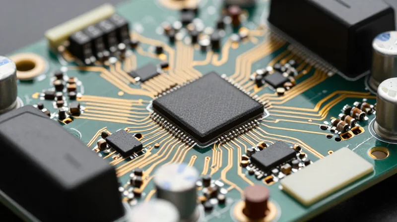
Engineering for Precision: The Anatomy of a High-Performance PCBA
A high-performance RFID PCBA achieves superior read ranges through a combination of low-noise RF amplification, specialized impedance matching, and high-speed digital signal processing (DSP) capable of filtering ambient electrical noise. Unlike standard hardware, these boards utilize advanced multi-layer stack-ups that effectively isolate the sensitive receiver chain from the high-power transmitter circuit, minimizing self-jamming and maximizing dynamic range.
Critical Hardware Components
| Component | Function | Impact on Performance |
|---|---|---|
| Front-End Module | Filtering & Amplification | Improves signal-to-noise ratio in high-density environments. |
| Surface Acoustic Wave (SAW) Filters | Frequency Selectivity | Reduces interference from adjacent cellular or Wi-Fi bands. |
| Impedance Matching Network | Power Transfer | Ensures maximum energy transfer to high-gain antennas. |
Technical FAQ
- Why does multi-layer PCB design matter for RFID?
Multi-layer boards allow for dedicated ground planes and differential signal routing, which significantly reduce EMI (Electromagnetic Interference) and crosstalk that otherwise degrade weak backscatter signals. - How does DSP impact real-world read rates?
Advanced DSP algorithms allow the reader to recover data from weak, phase-shifted signals that standard hardware would ignore as noise, enabling faster read rates in high-velocity logistics throughput. - What is the role of the SAW filter?
SAW filters are essential for isolating the specific UHF RFID frequency band, protecting the reader from being overwhelmed by nearby high-power wireless infrastructure.
Customization vs. Off-the-Shelf: The Strategic Edge
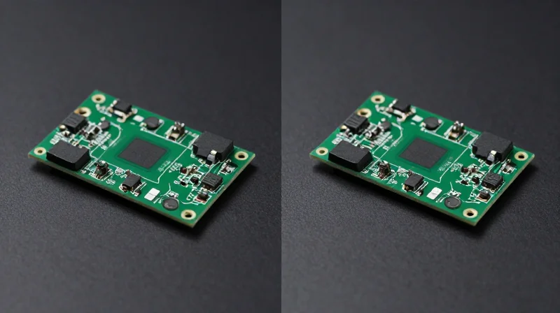
Customization vs. Off-the-Shelf: The Strategic Edge
In high-speed logistics, the choice between off-the-shelf and custom-engineered RFID PCBAs is fundamentally a choice between generalized compatibility and specialized performance. While generic hardware offers rapid deployment, it often falls short in complex industrial environments characterized by metal obstruction, electromagnetic interference, and rapid item throughput. Custom PCBA designs allow for the precise optimization of impedance matching, antenna orientation, and noise filtration—factors that directly correlate to increased read-rate accuracy and reduced operational bottlenecks.
| Feature | Off-the-Shelf Solutions | Custom PCBA Design |
|---|---|---|
| Implementation Speed | High (Plug-and-play) | Low (Design/Testing cycle) |
| Signal Interference | Susceptible to ambient noise | Engineered shielding/filtering |
| ROI Timeline | Short-term cost savings | Long-term operational efficiency |
| Environment Adaptation | Generic performance | Highly specific to facility layout |
Performance Metrics: Why Bespoke Wins
Bespoke PCBA development provides the strategic advantage of environmental tuning. By tailoring the board's radio frequency (RF) front-end to the specific physical characteristics of a warehouse—such as conveyor speeds and rack geometry—engineers can achieve read accuracy rates exceeding 99.9%. Off-the-shelf hardware, conversely, must maintain broad operating parameters to remain compatible with diverse use cases, often resulting in lower signal-to-noise ratios and reduced effective read ranges.
- Does custom hardware always offer higher ROI?
Not necessarily for low-complexity environments; however, in high-volume, signal-dense facilities, the reduction in labor costs and exception handling through higher read accuracy quickly offsets initial design investments. - Can I upgrade off-the-shelf components later?
Upgrading often leads to 'Frankenstein' systems that lack architectural cohesion, whereas custom designs integrate firmware, board layout, and antenna gain as a unified, optimized system from the start. - How do signal-dense environments affect standard PCBs?
Standard PCBs typically lack the localized filtering and specialized grounding required to mitigate the multi-path propagation and interference found in modern automated logistics centers.
Case Study: Reducing Labor Overhead Through Automation

The Challenge: Scaling Throughput in a High-Volume Environment
A global logistics leader faced a significant bottleneck at their primary inbound/outbound docks. Relying on manual barcode scanning, the facility struggled with high labor costs, data entry errors, and significant dwell time for inbound shipments. The integration of advanced RFID PCB assemblies was essential to transition from labor-intensive manual checks to automated, real-time inventory visibility.
Operational Performance Comparison
| Metric | Manual Scanning | Automated RFID Portals |
|---|---|---|
| Processing Time per Pallet | 120 seconds | 5 seconds |
| Accuracy Rate | 94.2% | 99.9% |
| Labor Cost per Dock | High (3 FTEs) | Low (Monitor only) |
Technical Implementation and Results
The deployment utilized bespoke industrial RFID PCB assemblies designed specifically for high-speed conveyor environments. By optimizing the signal-to-noise ratio at the hardware level, the system successfully mitigated the interference caused by adjacent metal shelving units—a failure point for previous off-the-shelf implementations.
- How was labor redeployed post-automation?
Warehouse staff were transitioned from repetitive scanning tasks to value-added activities like order picking, quality control, and exception management, significantly increasing overall workforce efficiency. - Why did the bespoke PCBA outperform standard hardware?
The custom PCB design allowed for adaptive antenna tuning and advanced noise filtering, enabling reliable tag detection despite the dense RF environment of the distribution floor. - What was the measurable ROI?
The facility achieved a complete break-even on the hardware investment within 9 months, driven primarily by the elimination of manual scan labor and the drastic reduction in shipping discrepancies.
Quantifying ROI: From Throughput to Bottom-Line Savings

The Financial Link: Throughput to Profitability
Transitioning to advanced industrial RFID reader PCBAs offers a predictable financial trajectory: enhanced read accuracy leads directly to reduced error correction cycles and lower labor costs. By minimizing 'read-miss' events—where legacy hardware fails to capture tag data—facilities avoid the costly ripple effects of shipment inaccuracies and manual reconciliation workflows. The primary ROI driver is the conversion of technical throughput improvements into reclaimed labor hours and reduced administrative overhead.
Key Performance Metrics for ROI Assessment
| Performance Metric | Operational Impact | Financial Outcome |
|---|---|---|
| First-Pass Read Rate | Reduced rework and re-scanning | Lower per-pallet handling cost |
| Signal Latency | Faster conveyor throughput | Increased daily volume capacity |
| Environmental Resilience | Lower hardware replacement rate | Extended asset lifecycle value |
Frequently Asked Questions on ROI Calculation
- How do I calculate the payback period for RFID PCBA upgrades?
Calculate the total cost of ownership (TCO), including the PCBA upgrade and integration, and divide by the monthly operational savings derived from labor displacement and reduced shipment error penalties. - What hidden costs should be factored into the ROI model?
Include integration testing time, potential downtime during installation, and the long-term cost savings of reduced maintenance cycles compared to legacy consumer-grade components. - Why does signal density affect the ROI calculation?
In signal-dense environments, high-performance PCBAs prevent data collision and interference, which directly correlates to fewer 'ghost reads' and less time spent on manual data verification.
Overcoming Environmental Hurdles in Signal Integrity
Navigating Signal Degradation in Metal-Dense Environments
The primary barrier to RFID efficacy in industrial settings is the presence of reflective metal surfaces and high-frequency interference. Advanced PCB assemblies overcome these hurdles by integrating specialized ground plane configurations and high-gain antenna arrays that focus RF energy while minimizing multipath interference caused by signal reflection.
Mitigation Techniques for RF Noise
| Challenge | PCB Solution | Performance Impact |
|---|---|---|
| Metal Reflection | Absorptive Ferrite Shielding | Reduced ghost reads and improved zoning |
| Electromagnetic Interference | Multi-layer Differential Pair Routing | Higher SNR and data fidelity |
| Signal Saturation | Automated Gain Control (AGC) circuits | Stable read rates in high-density zones |
Best Practices for Deployment Success
Deploying industrial RFID requires a holistic approach to PCB placement and environmental calibration. Leveraging custom assemblies allows for the fine-tuning of impedance matching networks, ensuring that power loss is minimized even when readers must be positioned near industrial machinery or high-voltage lines.
- How does PCB substrate selection impact signal integrity?
Using high-frequency, low-loss laminate materials like FR-4 alternatives or ceramic-filled substrates prevents dielectric absorption, preserving RF power for long-distance tag interrogation. - Can shielding solve all environmental noise issues?
Shielding is essential, but it must be paired with intelligent firmware that supports adaptive frequency hopping and filtering to remain effective against fluctuating ambient noise floor levels. - Why is impedance control critical for ROI?
Improperly matched impedance causes signal reflection back to the reader, increasing noise and reducing range, which ultimately leads to missed reads and decreased logistical throughput.
Future-Proofing Your Supply Chain Infrastructure
The Architectural Foundation of Scalable RFID
Future-proofing is not merely about choosing the fastest hardware today, but about selecting PCB assemblies that possess architectural elasticity. Advanced industrial RFID reader assemblies must support over-the-air (OTA) firmware updates, modular antenna connectivity, and multi-protocol software interfaces to ensure that your initial investment remains relevant as IoT demands grow.
Strategic Hardware Selection Criteria
| Feature | Future-Proof Value | ROI Impact |
|---|---|---|
| OTA Update Capability | Remote performance optimization | Lower maintenance costs |
| Multi-Protocol API | Seamless WMS integration | Reduced middleware investment |
| Modular RF Front-End | Adaptable to frequency shifts | Longer hardware lifecycle |
Integrating with Evolving WMS Platforms
The bottleneck in modern logistics is often the bridge between the edge device and the Warehouse Management System (WMS). Advanced PCB assemblies that leverage edge computing allow for local data filtering, reducing the bandwidth load and latency when communicating with cloud-native WMS platforms.
- How do I ensure my RFID hardware won't be obsolete in three years?
Prioritize assemblies with programmable logic (FPGA) and modular RF components that allow for frequency tuning and protocol upgrades as global standards change. - Why is edge processing critical for future-proofing?
As data volume increases, central servers become failure points; edge-capable PCBs process reads locally, ensuring the system remains responsive even if network connectivity is intermittent. - How do we simplify WMS integration?
Select hardware that natively supports standard APIs like MQTT or RESTful services, bypassing the need for expensive, proprietary middleware bridges.
Implementation Roadmap for Operational Success
The successful deployment of high-performance RFID reader PCBAs requires a structured, multi-phase implementation approach. Moving from legacy infrastructure to precision-engineered RFID systems hinges on mitigating signal interference and validating data integrity within your specific logistics environment.
Phased Implementation Framework
| Phase | Key Focus | Success Metric |
|---|---|---|
| Pilot Testing | Environment Calibration | Read Accuracy >99.5% |
| Infrastructure Rollout | Full-Scale Deployment | System Latency <100ms |
| Optimization | Predictive Maintenance | Hardware Uptime 99.9% |
Pilot Testing and Calibration
Before enterprise-wide deployment, establish a controlled pilot zone. This phase focuses on fine-tuning the RF power levels and antenna positioning of your PCBAs to account for local interference. Validating read rates against known throughput benchmarks is critical here to ensure the hardware meets performance specifications.
Operational Maintenance and Lifecycle Management
- How often should RFID reader PCBAs be recalibrated?
Recalibration should occur semi-annually or whenever major physical layout changes occur in the facility to ensure optimal tag capture and signal strength. - What is the primary indicator of hardware degradation?
A gradual decline in 'read zone' stability or increasing tag 'miss rates' are the earliest indicators that environmental interference or component aging requires attention. - How do we ensure firmware longevity?
Implement a centralized OTA (Over-the-Air) management system to push security patches and performance updates without requiring manual physical access to reader modules.
By following this structured roadmap, logistics managers can shift from reactive maintenance to a proactive infrastructure strategy, ensuring the long-term ROI of their RFID investment remains high despite changing industrial demands.
Investing in high-performance RFID PCB assemblies is more than a hardware upgrade; it is a fundamental shift toward operational transparency and fiscal discipline. By eliminating manual error and increasing scan throughput, your organization can reclaim thousands of man-hours annually. Contact our engineering team today to audit your current infrastructure and start your journey toward a fully optimized, high-velocity supply chain.
