
In the competitive landscape of RF engineering, the choice of substrate is often the hidden culprit behind delayed product launches and catastrophic field failures. While standard FR-4 offers an attractive low upfront cost, the hidden expenses of signal degradation and re-spins can destroy your project's ROI. We explore why professional Rogers 4350B fabrication is the strategic choice for modern high-frequency applications.
The Hidden Costs of Choosing the Wrong PCB Substrate
Engineers often face the temptation to reduce bill-of-materials costs by selecting lower-grade FR-4 alternatives for high-frequency applications. While these materials offer lower upfront procurement costs, they lack the stable dielectric constant (Dk) and low dissipation factor (Df) required for high-speed signal integrity. Selecting a substandard material essentially guarantees a flawed final product, forcing expensive design cycles that negate any initial savings and severely impact the overall ROI of the project.
The Financial Impact of Material Inconsistency
When a substrate exhibits poor thermal coefficient of dielectric constant, the impedance of transmission lines drifts during operation. In high-frequency environments, this leads to significant signal attenuation and phase distortion. The following comparison highlights why prioritizing performance-grade laminates like those from Rogers Corporation is a strategic fiscal decision.
| Parameter | Standard FR-4 | High-Frequency Laminate |
|---|---|---|
| Dk Stability | Low | High |
| Signal Loss (Df) | High | Extremely Low |
| Redesign Probability | High | Low |
| Total Cost of Ownership | Higher (due to iteration) | Lower (due to first-pass success) |
Frequently Asked Questions Regarding Material Selection
- Why does dielectric loss increase costs?
Higher loss requires more aggressive amplification and signal conditioning circuits, which adds complexity, increases board size, and raises component costs. - How do thermal inconsistencies trigger redesigns?
If the substrate expands or its electrical properties change significantly with temperature, the circuit will fail to meet RF specifications under field-operating conditions, mandating a full PCB respin. - Does switching to Rogers always lower total ROI?
When factoring in the 'cost of failure'—which includes delayed market entry, engineering hours, and wasted manufacturing batches—optimized laminate selection almost always yields a superior return on investment.
Why FR-4 Falls Short in High-Frequency Domains

The Performance Gap: Dielectric Loss and Stability
While FR-4 is the industry standard for low-cost digital electronics, its chemical composition—specifically the epoxy resin and glass fiber reinforcement—introduces significant signal integrity issues at microwave frequencies. As operating frequencies increase into the GHz range, the dissipation factor (Df) of FR-4 rises sharply, leading to substantial signal attenuation and heat generation that compromises system reliability.
| Parameter | FR-4 (Typical) | High-Frequency Laminate (Rogers) |
|---|---|---|
| Dissipation Factor (Df) at 10GHz | 0.015 - 0.025 | 0.001 - 0.004 |
| Dielectric Constant (Dk) Stability | Poor (Variable with Freq/Temp) | Excellent (Tight Tolerance) |
| Moisture Absorption | High | Negligible |
Key Limitations of FR-4
- High Dissipation Factor (Df)
FR-4 is inherently 'lossy.' At high frequencies, a large portion of the electromagnetic wave energy is absorbed by the substrate and converted into heat, resulting in unacceptable signal degradation. - Unstable Dielectric Constant (Dk)
The Dk of FR-4 varies significantly with frequency, temperature, and moisture content. This inconsistency leads to unpredictable impedance shifts, causing reflections and phase errors in high-speed circuits. - Glass Weave Effect
The uneven distribution of glass fibers in standard FR-4 creates localized variations in Dk, which causes skew in differential pairs—a critical failure point for high-speed serial data transmission.
For engineers aiming to maximize ROI, relying on FR-4 for microwave designs is a false economy. The resulting signal integrity failures often necessitate multiple board spins, expensive troubleshooting, and potential field failures. Investing in specialized materials like Rogers laminates allows for predictable performance, reduced signal loss, and the ability to design more compact, efficient architectures that outweigh the initial material cost premium.
The Technical Edge: Understanding Rogers 4350B Properties
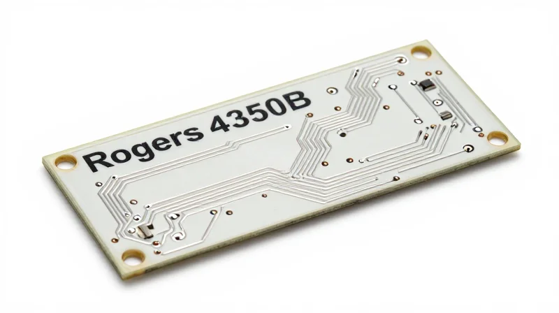
Rogers 4350B is a hydrocarbon/ceramic laminate engineered to provide superior high-frequency performance compared to traditional epoxy resins. Its unique chemical composition bridges the gap between the low loss requirements of high-frequency signal integrity and the standard fabrication processes used in the PCB industry, effectively maximizing ROI by reducing the need for specialized exotic material handling.
Key Dielectric and Thermal Properties
| Property | Rogers 4350B Value | Benefit to RF Design |
|---|---|---|
| Dielectric Constant (Dk) | 3.48 @ 10 GHz | Excellent impedance control and consistent signal propagation. |
| Dissipation Factor (Df) | 0.0037 @ 10 GHz | Lower insertion loss and heat dissipation. |
| Tg (Glass Transition) | >280°C | Exceptional thermal stability during reflow soldering. |
| CTE (Z-axis) | 46 ppm/°C | High reliability for plated through-hole structures. |
Why 4350B Sets the Industry Standard
The primary advantage of Rogers 4350B lies in its stability across varying temperatures and frequencies. Unlike FR-4, which exhibits significant Dk drift as temperatures rise or as frequencies enter the multi-GHz range, 4350B maintains a remarkably flat profile. This reliability prevents phase shift issues and ensures that the finished hardware meets stringent VSWR requirements without iterative prototyping.
- How does Rogers 4350B simplify the fabrication process?
Unlike PTFE-based laminates that require specialized sodium naphthalene treatments for layer bonding, 4350B can be processed using standard FR-4 PCB manufacturing techniques, significantly lowering production overhead. - Is 4350B suitable for multi-layer designs?
Yes, it is specifically designed to be compatible with standard multi-layer construction, allowing engineers to mix it with lower-cost materials in hybrid layups to optimize total system cost. - Does the high Tg affect assembly?
The high glass transition temperature ensures the material remains dimensionally stable during lead-free soldering cycles, preventing via barrel cracking and trace lifting common in lower-tier materials.
Mitigating Signal Integrity Failures Through Material Precision
The primary driver of high-frequency design failure is the unpredictable interaction between copper traces and the substrate. By utilizing high-performance Rogers laminates, engineers gain tighter control over the dielectric constant (Dk) and dissipation factor (Df), ensuring that signal paths behave as simulated. This consistency effectively eliminates the 'tweak and test' cycle, as board performance matches theoretical models from the first prototype.
Consistency as a Cost-Reduction Lever
When substrates exhibit wide tolerances in Dk across different frequency bands or temperatures, impedance matching becomes a moving target. Rogers materials are engineered for extreme stability, allowing for the design of precise microstrip and stripline structures without the need for excessive margin-of-error compensation or post-fabrication trace tuning.
| Parameter | Standard FR-4 | Rogers High-Freq Laminate | Impact on ROI |
|---|---|---|---|
| Dk Tolerance | +/- 10% | +/- 0.05 | Reduced impedance variability |
| Dissipation Factor | High (0.02) | Low (0.003) | Lower insertion loss |
| Thermal Stability | Low | High | Eliminates frequency drift |
Mitigating Failure: Engineering FAQs
- How does Dk stability affect signal integrity?
Stable Dk prevents impedance discontinuities along the signal path, which minimizes reflections and ensures consistent signal velocity, directly reducing bit error rates. - Can material selection reduce testing time?
Yes. By choosing materials with predictable dielectric behavior, engineers can avoid the iterative diagnostic testing typically required to compensate for substrate-induced phase shifts. - Why does lower insertion loss equate to ROI?
Lower loss means signal power is maintained, often eliminating the need for expensive high-power amplification stages or additional signal repeaters at the board level.
Accelerating Time-to-Market with Streamlined Prototyping
Reducing Design Iterations with Material Reliability
The primary cause of delayed high-frequency product launches is the 're-spin' cycle necessitated by discrepancies between simulation models and physical prototype performance. By utilizing Rogers high-performance laminates, engineers gain access to consistent dielectric constant (Dk) and dissipation factor (Df) values that remain stable across temperature and frequency shifts. This predictability ensures that the prototype behaves exactly as the simulation predicted, effectively eliminating the need for multiple hardware iterations.
Comparison of Prototyping Approaches
| Parameter | FR-4 Prototyping | Rogers Material Prototyping |
|---|---|---|
| Dk Stability | Poor (Varies with Frequency) | Excellent (Stable to 77GHz) |
| Design Iterations | 3-5 Cycles | 1-2 Cycles |
| Tuning Requirements | Extensive Impedance Tuning | Minimal Manual Adjustment |
| First-Pass Yield | Low | High |
Frequently Asked Questions
- Why does material selection influence project velocity?
When materials like Rogers exhibit tight tolerance controls, simulation accuracy increases. This high correlation between CAD models and physical boards allows teams to bypass extensive post-fabrication tuning. - Does higher material cost hinder ROI?
No. While the per-board cost is higher than FR-4, the total ROI is maximized by saving weeks of engineering time and avoiding the manufacturing expenses associated with multiple prototype iterations. - How does Rogers simplify the testing phase?
Because the material loss is minimized and the impedance is controlled, engineers spend less time troubleshooting signal integrity issues and more time validating core circuit functionality.
Long-Term Reliability and Lifetime Cost Reduction
The Hidden Cost of Material Failure
When high-frequency PCB projects utilize inferior, low-cost laminates, the initial savings are often eclipsed by systemic failures. Budget materials frequently exhibit inconsistent dielectric constants (Dk) and thermal instability, which cause signal drift over time. This instability leads to degradation in field environments, resulting in product returns and costly maintenance cycles. By standardizing on high-performance materials like Rogers, manufacturers stabilize the product lifecycle, transforming a variable maintenance expense into a predictable, high-reliability operation.
Comparative Impact on Operational Expenses
| Failure Driver | Low-Cost Laminate Impact | Rogers Laminate Advantage |
|---|---|---|
| Thermal Cycling | High risk of delamination/cracking | Superior CTE stability ensures integrity |
| Field Returns | Frequent warranty claims | Negligible failure rates |
| Maintenance | Requires manual impedance tuning | Maintenance-free performance |
Long-Term Reliability FAQ
- How do Rogers materials specifically extend product lifetime?
Rogers materials provide superior thermal conductivity and moisture resistance, preventing the common aging symptoms that compromise electrical performance in challenging environments. - Does higher initial material cost actually lower the total cost of ownership?
Yes. While the bill-of-materials cost is higher, the ROI is realized through the avoidance of expensive engineering rework, scrapped production batches, and the high logistical costs of servicing failed units in the field. - Can material selection influence warranty liabilities?
Absolutely; choosing laminates with a proven track record of environmental resilience allows manufacturers to offer extended warranties with lower risk, directly enhancing the brand's competitive market position.
Case Study: Transitioning from FR-4 to Rogers for RF Reliability
The Challenge: Performance Bottlenecks in FR-4 Prototypes
An industrial RF communication firm initially utilized standard FR-4 for its high-frequency power amplifier line. Despite the lower initial material costs, the team encountered significant phase shifts and excessive signal attenuation at frequencies above 3GHz. This resulted in a failure to meet regulatory emission standards, necessitating multiple hardware iterations and extensive manual tuning of matching circuits.
Comparative Performance Metrics
| Parameter | FR-4 Material | Rogers 4350B | Impact on ROI |
|---|---|---|---|
| Signal Loss (dB/in @ 10GHz) | ~0.25 | ~0.05 | Higher efficiency |
| Dielectric Constant Stability | Low | High | Less board tuning |
| Development Cycles | 4-5 iterations | 1-2 iterations | Lower labor cost |
Strategic Outcomes and Cost Analysis
Transitioning to Rogers 4350B laminates allowed the engineering team to leverage high-frequency stability, which directly translated into fewer PCB spins and a accelerated time-to-market. By eliminating the necessity for complex compensating components, the Bill of Materials (BOM) was simplified, offsetting the premium cost of the Rogers laminate.
Key Takeaways from the Transition
- Why did the overall project cost decrease despite expensive materials?
The primary cost savings were realized through a 60% reduction in labor hours spent on hardware debugging and a shortened prototyping phase. - Was the performance increase measurable in field reliability?
Yes, switching to Rogers reduced thermal sensitivity, leading to a 15% reduction in field failures reported over the first six months of deployment. - Does this strategy apply to all high-frequency projects?
While not every project requires high-frequency laminates, any system operating above 2GHz typically benefits from the impedance control and reduced dielectric loss offered by Rogers.
Best Practices for Collaborative PCB Design and Fabrication
Strategic Collaboration for Material Optimization
Achieving maximum ROI when utilizing high-frequency materials requires shifting from a siloed design approach to a collaborative partnership. By engaging your fabricator during the preliminary stack-up definition, you can avoid costly design iterations, mitigate signal integrity risks, and ensure that the selected Rogers laminate is perfectly aligned with both performance requirements and manufacturing capabilities.
Collaborative Best Practices Table
| Phase | Action Item | ROI Benefit |
|---|---|---|
| Pre-Layout | Joint Stack-up Review | Prevents impedance mismatches and material waste. |
| Dfm Analysis | Fabricator Feedback | Reduces scrap rates and enhances yields. |
| Prototyping | Shared Design Rules | Ensures production-readiness from first build. |
Common Questions for Fabricators
- How does the chosen Rogers laminate interact with specific plating processes?
Rogers materials have distinct thermal and chemical profiles compared to traditional FR-4; knowing how your fabricator manages these ensures long-term bond reliability. - Can you provide localized panel utilization data?
Optimizing how boards are nested on a manufacturing panel can significantly reduce raw material waste, directly lowering the cost per unit of expensive high-frequency laminates. - What are the tolerances for layer-to-layer registration for this specific material?
Understanding the registration capabilities of your fabricator early allows you to design wider tolerances into your critical RF paths, minimizing board failure rates.
Ultimately, the most successful projects are those where the designer understands the fabrication constraints of the high-frequency material. Establishing a feedback loop—where the fabricator reviews the design for manufacturability before the final Gerber release—is the most effective way to protect your investment in premium Rogers laminate technology.
Selecting the right material is not just a technical requirement; it is a financial strategy that dictates the success of your high-frequency project. By investing in Rogers 4350B, you eliminate common signal bottlenecks and secure the reliability your clients demand. Ready to optimize your next RF design? Contact our engineering team today for a comprehensive material consultation and project review.
