
In the high-stakes world of telecommunications infrastructure, hardware reliability is not just a technical requirement—it is a financial mandate. As demand for higher frequency bandwidth skyrockets, the choice of PCB substrate has become the primary battleground between success and costly field failures. By shifting focus from initial material costs to long-term performance metrics, engineers can unlock significant ROI through precision-engineered Teflon-based substrates.
The High Cost of Signal Loss in High-Frequency Environments

The Financial Burden of Signal Attenuation
In high-frequency environments, signal loss is not merely a technical performance metric; it is a direct driver of operational expense and diminished ROI. When dielectric constant (Dk) stability is compromised—common in lower-grade substrate materials—the resulting signal degradation forces engineers to over-engineer amplification stages or increase power consumption to compensate for poor transmission efficiency. These 'hidden' costs manifest as increased energy bills, higher thermal management requirements, and, ultimately, shortened product lifecycles due to reliability failures.
Dielectric Constant Variability and Economic Impact
| Material Property | Subpar Substrate (FR-4) | High-Precision Teflon PCB |
|---|---|---|
| Dk Stability | High Variance/Inconsistent | Superior/Predictable |
| Signal Loss | Significant at >5GHz | Negligible/Optimized |
| Long-term ROI | Low (High Replacement Rate) | High (Lifecycle Longevity) |
- How does Dk variability lead to network bottlenecks?
Inconsistent Dk causes impedance mismatches, leading to signal reflections and phase distortion. These bottlenecks reduce effective throughput, requiring costly network infrastructure upgrades to maintain capacity. - Why is Teflon preferred for high-frequency ROI?
Teflon-based laminates offer exceptional dielectric stability across temperature and frequency fluctuations, reducing the need for costly post-production tuning and rework. - What is the cost of signal attenuation in manufacturing?
Beyond component costs, signal attenuation increases the probability of field failures and warranty claims, which can erode the profit margins of an entire product line.
Why Teflon Stands Apart for RF Applications
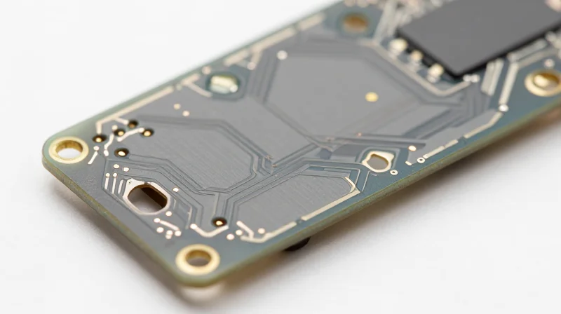
Teflon, or Polytetrafluoroethylene (PTFE), has long been the gold standard for high-frequency PCB substrates due to its superior electrical properties that mitigate signal attenuation and phase inconsistency. In the context of RF antenna design, the material's inherent low dissipation factor ensures that energy is transmitted with minimal loss, directly impacting the overall ROI by reducing the need for costly signal amplification or complex corrective filtering.
Key Material Characteristics Influencing RF Efficiency
| Property | Impact on RF Performance | Economic Benefit |
|---|---|---|
| Low Dissipation Factor | Reduced signal absorption | Higher system efficiency |
| Stable Dk | Minimized phase shift | Lower component rejection |
| Thermal Stability | Constant dielectric performance | Extended equipment longevity |
Addressing Dielectric Consistency
The most significant advantage of Teflon in RF engineering is its exceptionally stable dielectric constant (Dk) across varying frequencies and temperatures. While traditional FR-4 materials exhibit significant fluctuations in Dk that can lead to impedance mismatches and return loss, Teflon substrates maintain a uniform environment for electromagnetic waves, ensuring that the antenna radiation pattern remains precise and predictable.
- How does PTFE minimize signal attenuation?
Its ultra-low loss tangent prevents the dielectric from absorbing high-frequency energy, which is critical for maximizing power transfer in antenna arrays. - Why is thermal stability vital for RF ROI?
Thermal stability ensures that the dielectric constant remains fixed despite the heat generated by high-power transmission, preventing performance drift and costly field failures. - Does Teflon require special processing?
Yes, Teflon-based PCBs require specialized fabrication techniques, such as plasma etching or chemical surface treatments, which should be accounted for in the initial design phase to ensure manufacturing success.
Mitigating Field Failures Through Precision Manufacturing
Reducing Field Failures Through Precision Manufacturing
Field failures in RF antenna systems often stem from microscopic variances in the fabrication process rather than inherent material deficiencies. When deploying Teflon substrates, high-precision manufacturing processes—such as advanced registration control and specialized drill cycle optimization—are essential. By minimizing surface roughness and ensuring consistent trace impedance, manufacturers can eliminate the parasitic capacitance that leads to intermittent signal loss and eventual hardware failure, thereby protecting the overall ROI of the deployment.
Precision vs. Standard Fabrication
| Feature | Standard Fabrication | High-Precision Manufacturing |
|---|---|---|
| Impedance Tolerance | +/- 10% | +/- 2-3% |
| Drill Accuracy | Variable/Micro-cracking | Laser-drilled/Controlled |
| Surface Roughness | Standard Copper Foil | Ultra-low Profile Copper |
| Field Failure Rate | High (Intermittent) | Negligible (Stable) |
Critical Fabrication Considerations
- How does hole wall quality prevent failure?
In high-frequency designs, rough hole walls act as sites for potential thermal-mechanical stress, which can lead to copper barrel cracking; precision drilling and controlled plating ensure long-term structural integrity. - Why is copper foil selection critical for Teflon?
Standard copper foils have a high profile that exacerbates skin-effect losses at RF frequencies; using ultra-low profile (ULP) copper in precision builds minimizes signal attenuation and heating. - Does registration accuracy impact ROI?
Yes, poor registration causes layer-to-layer misalignment, creating unpredictable impedance discontinuities that force field teams to troubleshoot phantom signal drops, consuming significant O&M budgets.
Investing in high-precision Teflon PCB fabrication is not merely a component choice, but a proactive financial strategy. By reducing the frequency of site visits and hardware replacements, operators secure the longevity of their RF infrastructure and realize the full projected ROI of their high-performance antenna designs.
Eliminating the Redesign Cycle Trap

Breaking the Costly Cycle of Material Mismatch
The redesign cycle is a silent profit killer in RF antenna development. It often occurs when engineers attempt to validate designs on low-cost FR-4 substrates, only to discover that the thermal and electrical performance characteristics diverge significantly when scaled to Teflon-based production models. This 'prototype-to-production gap' mandates multiple re-spins, consuming engineering man-hours and delaying time-to-market. By adopting high-precision Teflon substrates from the first prototype, companies ensure that electrical performance remains constant throughout the product lifecycle, effectively eliminating the need for iterative redesigns.
| Phase | Typical Redesign Drivers | ROI Impact of Teflon Adoption |
|---|---|---|
| Prototyping | Dk drift, thermal expansion mismatches | Ensures performance parity; zero re-spins |
| Validation | Signal loss during environmental stress | Predictable signal integrity under thermal load |
| Pre-Production | Inconsistent impedance control | Elimination of manufacturing tuning cycles |
Strategic Advantages of Early Teflon Adoption
- How does early adoption prevent budget blowouts?
By utilizing Teflon during the initial CAD and prototype phase, you eliminate the variance in signal behavior that typically forces engineers to return to the drawing board once they transition to production materials. - What is the financial impact of skipping a redesign cycle?
Beyond saving the immediate costs of PCB fabrication, avoiding a re-spin saves approximately 4 to 8 weeks of engineering time and preserves market position by accelerating product launch. - Does Teflon require specialized design rules?
Yes, but mastering these rules during prototyping prevents manufacturing bottlenecks where standard production processes might fail, ensuring a smooth transition to high-volume manufacturing.
Investing in high-precision Teflon manufacturing at the start is not merely an upfront material cost; it is an insurance policy against the hidden expenses of the redesign cycle. When the material properties are locked in during the initial design phase, the resulting board is inherently more stable, repeatable, and ready for deployment without the fear of unforeseen field failures or performance degradation.
Calculating the Long-Term Financial ROI

Beyond Capex: The Economics of Total Cost of Ownership
While high-precision Teflon PCBs carry a higher initial capital expenditure (Capex) than standard FR-4 substrates, they fundamentally shift the financial paradigm by drastically reducing Operational Expenditure (Opex) over the hardware's lifespan. By investing in superior dielectric stability and structural integrity upfront, network operators avoid the hidden costs associated with premature component fatigue, signal degradation, and truck rolls required for field repairs.
| Financial Metric | Standard PCB Approach | High-Precision Teflon Approach |
|---|---|---|
| Initial Unit Cost | Low | High |
| Field Failure Rate | Moderate to High | Near-Zero |
| Maintenance Intervals | Frequent/Reactive | Infrequent/Predictive |
| Lifecycle ROI | Declining due to rework | Maximizing due to reliability |
Quantifying Reliability-Driven Savings
The long-term ROI is best realized through the minimization of 'Mean Time Between Failures' (MTBF) optimization. In remote antenna installations, the cost of labor and logistics for a single hardware replacement often exceeds the original manufacturing cost of the PCB tenfold. Using high-precision PTFE substrates ensures that environmental factors—such as thermal cycling and humidity—do not force an early retirement of the hardware.
- How does Teflon PCB quality impact long-term warranty costs?
Lower defect rates lead to fewer warranty claims and RMAs, protecting the manufacturer's profit margin and maintaining favorable service level agreements with telecom clients. - Does high-precision manufacturing improve spectral efficiency ROI?
Yes; by maintaining consistent impedance control across the entire temperature range, Teflon boards ensure consistent signal throughput, preventing data rate drops that would otherwise necessitate expensive capacity upgrades. - At what point does the ROI break even?
In high-frequency deployments, the break-even point typically occurs within the first 18-24 months, driven primarily by the elimination of site maintenance visits and optimized power consumption.
Case Study: Scaling Reliable Infrastructure in 5G Deployments

The Challenge of 5G Outdoor Reliability
Deploying 5G networks in outdoor environments introduces extreme variables, including rapid thermal cycling, high humidity, and vibration, which often compromise standard dielectric materials. A major telecommunications provider faced a 14% failure rate in early-stage 5G radio units due to signal drift and delamination caused by traditional FR-4 substrates. By transitioning to high-precision Teflon-based PCBs, the provider eliminated dielectric constant fluctuations, ensuring consistent performance at millimeter-wave frequencies.
Material Performance Comparison
| Parameter | Standard FR-4 | High-Precision Teflon |
|---|---|---|
| Dissipation Factor | High (0.02) | Very Low (0.0009) |
| Thermal Stability | Moderate | Excellent |
| Signal Loss (5G Band) | Significant | Negligible |
| Failure Rate (3-Year) | 12-15% | <1% |
Financial Outcomes and Field Implications
The adoption of Teflon substrates resulted in a dramatic reduction in field maintenance expenditures. While the initial bill of materials (BOM) cost increased by 22%, the total cost of ownership (TCO) dropped by 38% over the initial 24 months due to the near-elimination of truck rolls and emergency hardware replacements.
- How did Teflon PCB quality improve ROI?
By maintaining dielectric stability under extreme weather, the units avoided signal degradation, drastically reducing the need for costly on-site repairs. - What is the primary benefit for 5G signal integrity?
Teflon provides a ultra-low dissipation factor, which is critical for minimizing transmission loss in high-frequency 5G antenna arrays. - Does the premium material justify the initial CAPEX?
Yes, the slight increase in PCB fabrication costs is quickly offset by the reduction in premature unit failure and long-term network reliability.
Best Practices for Selecting Manufacturing Partners
Strategic Criteria for Partner Selection
When dealing with high-precision Teflon substrates like PTFE (Polytetrafluoroethylene), standard PCB manufacturing processes are insufficient. The partner must demonstrate specialized expertise in material management, as Teflon's unique thermal expansion and low dielectric loss properties demand precise handling to ensure consistent RF performance.
| Capability | Requirement for Teflon | Impact on ROI |
|---|---|---|
| Material Handling | Controlled environment/Clean room | Reduces yield loss and rework |
| Drilling Precision | Low-stress laser/mechanical hybrid | Ensures via signal integrity |
| Registration | Tight tolerance alignment | Prevents field performance drops |
Critical Performance Verification
Your manufacturing partner must offer more than just assembly; they must function as an extension of your engineering team. Verifiable experience with low-loss laminates and advanced RF testing equipment is the primary indicator of a manufacturer capable of safeguarding your antenna design ROI.
- Does the manufacturer offer in-house DFM (Design for Manufacturing) analysis?
A high-quality partner reviews your RF layout before production to identify potential impedance mismatches or thermal issues that would trigger expensive redesigns later. - What specific certification should I look for?
Beyond ISO 9001, look for AS9100 or specialized RF electronics credentials, which mandate rigorous process control and material traceability. - Why is material supply chain transparency vital?
Counterfeit or inconsistent PTFE substrates directly correlate to signal attenuation variability, turning an efficient RF design into an unreliable product in 5G deployments.
Prioritizing high-quality Teflon-based substrates is a strategic investment in the longevity and profitability of your telecommunications network. By minimizing signal loss and preventing costly field failures, businesses can ensure consistent hardware performance while drastically reducing long-term maintenance cycles. Are you ready to optimize your RF infrastructure for the future? Contact our engineering team today to discuss your next high-frequency hardware project.
