
In the high-stakes world of industrial automation, Variable Frequency Drives (VFDs) are the heartbeat of operational efficiency. Yet, even minor inconsistencies in PCB assembly or design can lead to catastrophic field failures. As energy costs rise and downtime becomes increasingly expensive, understanding the intersection of precision manufacturing and long-term asset reliability is no longer optional—it is a business imperative.
The Direct Correlation Between PCB Design and VFD Reliability
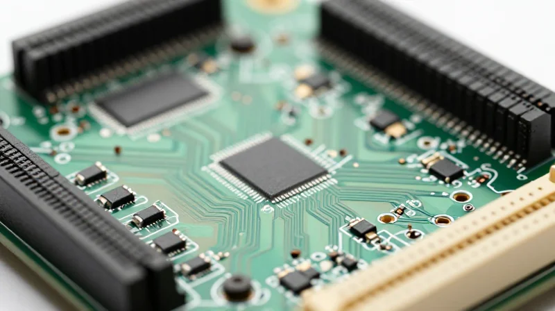
The performance of a Variable Frequency Drive (VFD) is inseparable from the integrity of its printed circuit board (PCB). Because VFDs operate in high-power, high-frequency environments, even minor deviations in PCB design can lead to premature field failure. By focusing on thermal management, electromagnetic compatibility (EMC), and robust trace architecture, manufacturers can significantly reduce downtime and maximize their operational return on investment.
Critical Factors in PCB Design Reliability
| Design Factor | Impact on Reliability | Mitigation Strategy |
|---|---|---|
| Thermal Management | Excess heat degrades capacitors and semiconductors. | Strategic component placement and thermal via arrays. |
| Trace Routing | Inductive noise causes signal interference. | Controlled impedance and minimized loop areas. |
| Material Selection | High-temperature environments cause substrate delamination. | High-Tg (glass transition temperature) FR-4 materials. |
Addressing Common Reliability Challenges
- How does trace width impact current density in VFDs?
Insufficient trace width increases electrical resistance, leading to excessive heat generation. Proper sizing according to IPC-2221 standards is essential to prevent copper traces from acting as fuses during power surges. - Why is component placement critical for EMC?
VFDs generate significant switching noise. Placing sensitive control logic too close to high-power IGBT circuits without proper decoupling or isolation leads to signal corruption and false trips. - Can conformal coating improve PCB reliability?
Yes, in industrial environments, conformal coating protects the assembly from conductive dust, moisture, and corrosive atmospheres, effectively doubling the lifespan of the PCB in harsh field conditions.
Implementation Best Practices
To achieve superior reliability, engineering teams must prioritize design-for-manufacturability (DFM) and design-for-reliability (DFR). This involves using automated tools to perform thermal modeling during the layout phase and adhering to strictly controlled stack-up requirements to manage parasitic capacitance. Investing in these rigorous design protocols early in the cycle prevents the costly 'fix-it-in-the-field' scenario that erodes long-term ROI.
Anatomy of a Failure: Why Standard Manufacturing Falls Short
The Price of Compromise in PCB Production
Standard manufacturing processes often prioritize initial capital expenditure savings over long-term durability, leading to systemic vulnerabilities. When corners are cut in material selection, process control, or inspection protocols, the resulting PCBs struggle to survive the extreme vibration, thermal cycling, and high-voltage stress characteristic of Variable Frequency Drive (VFD) applications.
Common Failure Modes in VFD Electronics
| Failure Mechanism | Primary Root Cause | Resulting Impact |
|---|---|---|
| Solder Joint Fatigue | Inconsistent reflow profiles | Open circuits/intermittent signals |
| Dielectric Breakdown | Insufficient board cleanliness | Arcing and short circuits |
| Thermal Delamination | Inferior FR-4 substrate grades | Layer separation/component loss |
Frequently Asked Questions Regarding Manufacturing Shortfalls
- Why does standard solder mask application lead to field failures?
Inconsistent mask thickness often leads to insufficient insulation between high-voltage traces, increasing the likelihood of conductive path formation when exposed to moisture or particulate contaminants. - How does PCB cleanliness impact VFD longevity?
Inadequate cleaning processes leave ionic residues on the board. In a high-voltage VFD environment, these residues attract moisture, lowering surface insulation resistance and causing catastrophic dielectric breakdown. - Is standard FR-4 sufficient for high-heat VFD environments?
Not always. Standard FR-4 often lacks the necessary Glass Transition Temperature (Tg) rating to handle the thermal cycling generated by high-switching frequency power components, eventually leading to pad lifting and internal layer separation.
Precision Assembly: The Role of Advanced Surface Mount Technology
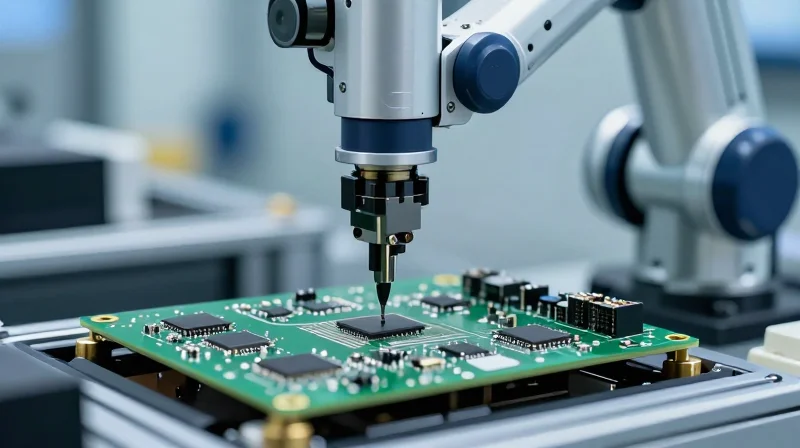
In the context of VFD (Variable Frequency Drive) manufacturing, standard assembly processes often fail to meet the rigorous demands of power electronics. Precision SMT is not merely about component placement; it is the cornerstone of structural integrity. By utilizing high-accuracy pick-and-place systems, automated optical inspection (AOI), and precise reflow profiling, manufacturers can minimize the mechanical stresses that lead to premature solder joint fatigue and dielectric failure in the harsh environments where VFDs typically operate.
Optimizing SMT for High-Power Reliability
To achieve a high ROI, the assembly process must focus on the microscopic variables that govern long-term reliability. Advanced SMT lines now integrate real-time feedback loops that calibrate placement force and solder paste volume based on board-specific thermal mass. This ensures that large power components—often the most vulnerable points in a VFD—are bonded with uniform intermetallic layers, providing the vibration resistance necessary for heavy-duty industrial motor applications.
| Parameter | Standard Assembly Impact | Advanced SMT Impact |
|---|---|---|
| Solder Joint Uniformity | High variance, potential voids | Consistent grain structure, void-free |
| Component Alignment | +/- 0.05mm, thermal stress risk | Micron-level accuracy, balanced stress |
| Thermal Conductivity | Inefficient interface | Optimized bond-line thickness |
Frequently Asked Questions: Precision Assembly
- How does SMT precision reduce VFD field failures?
Precision placement reduces mechanical stress and solder voids, which are the primary precursors to intermittent electrical failures and thermal runaways in high-power drives. - Why is reflow profiling critical for power electronics?
Controlled heating profiles prevent thermal shock to sensitive capacitors and semiconductor packages, ensuring the longevity of the intermetallic bonds during operation. - Can advanced SMT improve ROI?
Yes, by reducing the cost of warranty repairs and downtime, the upfront investment in high-precision assembly pays for itself through increased product service life and reduced scrap rates.
Optimizing for Harsh Environments: Protective Coatings and Material Selection
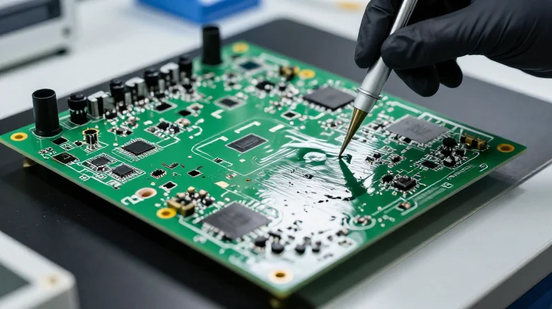
For VFDs deployed in harsh industrial environments, the PCB is the primary point of failure. When subject to extreme temperature cycling, high humidity, and persistent vibration, standard FR-4 substrates and basic spray-on coatings often succumb to dielectric degradation and structural fatigue. Achieving a high ROI requires transitioning to specialized materials that prioritize thermal stability and chemical resistance.
Substrate Material Selection: Beyond Standard FR-4
The choice of substrate dictates the physical longevity of the VFD controller. In environments with rapid thermal expansion and contraction, standard FR-4 fails due to its relatively low glass transition temperature (Tg). High-Tg materials provide superior dimensional stability, ensuring that plated through-holes do not fracture under thermal stress.
| Material Type | Key Advantage | Best Use Case |
|---|---|---|
| High-Tg FR-4 | Thermal stability up to 180°C | High-power density motor drives |
| Polyimide | Extreme thermal and chemical resistance | Aerospace or deep-mining VFDs |
| Metal Core (IMS) | Superior heat dissipation | High-heat power stages and IGBT modules |
Conformal Coating Strategies for Environmental Immunity
Conformal coatings serve as the final barrier against humidity, corrosive gases, and conductive dust. To maximize ROI, manufacturers should move away from manual spray application, which is prone to uneven thickness and voids, toward automated selective coating processes. Parylene (Chemical Vapor Deposition) offers the highest level of protection, creating a pinhole-free, molecular-level barrier that conforms perfectly to complex geometries.
Frequently Asked Questions
- Why is selective coating preferred over full-board dipping?
Selective coating prevents contamination of critical components like connectors and high-power terminals that require mechanical contact, ensuring better reliability and simpler assembly. - How does high-Tg material improve VFD ROI?
By preventing solder joint fatigue caused by coefficient of thermal expansion (CTE) mismatch, high-Tg materials significantly extend the mean time between failures (MTBF), reducing costly downtime. - Is Parylene always the best choice?
While Parylene provides superior environmental protection, its cost is higher. Use it for mission-critical applications where failure costs exceed the investment in premium coating processes.
Mitigating Energy Loss Through Efficient Circuit Architecture

Reducing Parasitic Resistance and Thermal Loss
Energy loss in Variable Frequency Drives (VFDs) is frequently exacerbated by sub-optimal PCB layout, where excessive trace resistance and poor thermal management lead to heat dissipation. By employing advanced routing techniques and high-conductivity copper layers, manufacturers can mitigate I²R losses, ensuring that power delivery remains efficient even under heavy industrial loads.
Efficiency Comparison: Standard vs. Optimized Layouts
| Feature | Standard PCB Design | Optimized VFD Architecture |
|---|---|---|
| Copper Thickness | 1 oz standard | 2 oz - 4 oz heavy copper |
| Trace Impedance | Higher resistance | Minimized parasitic loss |
| Thermal Dissipation | Concentrated hotspots | Uniform heat distribution |
| Energy Efficiency | Lower | Higher (reduced waste) |
Design Strategies for Minimal Energy Waste
- How does heavy copper weight improve efficiency?
Using heavier copper weights (2oz to 4oz) lowers the electrical resistance of high-current paths, preventing energy from being lost as excess heat. - Why is trace geometry critical in VFDs?
Optimizing trace width and length reduces parasitic inductance and resistance, which is essential for maintaining power integrity and decreasing switching losses. - Does PCB layout affect component longevity?
Yes; by minimizing internal resistance, the board operates at a lower steady-state temperature, directly reducing thermal degradation of sensitive semiconductor components.
Investing in high-performance circuit architecture is a cornerstone of maximizing ROI. While material costs may be higher initially, the substantial reduction in field failures and electricity consumption creates a superior lifecycle value proposition.
Quality Assurance Protocols: Ensuring Zero-Defect Manufacturing

The Imperative of Micro-Fault Detection
In the context of Variable Frequency Drive (VFD) systems, even microscopic solder bridges, hairline fractures, or component misalignment can lead to catastrophic field failures under operational stress. To achieve zero-defect manufacturing, we move beyond functional testing toward proactive inspection technologies that identify potential failure modes during the assembly stage, long before the PCB is commissioned in the field.
Comparative Inspection Technologies
| Technology | Primary Application | Benefit to VFD ROI |
|---|---|---|
| AOI | Surface mount component placement and solder joints | Rapid identification of assembly errors |
| X-Ray (AXI) | BGA/QFN hidden solder joints and internal delamination | Prevention of latent failures under thermal cycling |
| ICT/FCT | Electrical continuity and circuit functionality | Verification of drive control parameters |
Advanced Inspection Best Practices
- Why is X-ray testing non-negotiable for power-dense PCBs?
Modern VFD controllers rely heavily on high-density BGA components. X-ray inspection is the only reliable method to verify the integrity of solder joints hidden beneath these packages, ensuring no voids exist that could trigger thermal runaway. - How does AOI integration reduce long-term maintenance costs?
By automating the detection of defects like tombstoning or polarity reversals during the early stages of the SMT line, AOI prevents defective boards from ever entering the final assembly phase, significantly lowering warranty claims and field service dispatches. - What role does data logging play in quality optimization?
Storing inspection data for every serial-numbered board allows for precise root-cause analysis, enabling engineers to tune reflow oven profiles and component placement parameters for continuous manufacturing improvement.
By shifting from reactive testing to a data-driven inspection methodology, manufacturers can stabilize their yield rates and eliminate the high cost of field-based remediation. This strategy ensures that VFD components perform reliably throughout their intended lifecycle, directly protecting the ROI of the integrated industrial drive system.
The ROI Calculation: Lifecycle Cost vs. Initial Capital Investment
The traditional procurement mindset often prioritizes low initial capital expenditure (CAPEX), yet this approach frequently triggers hidden costs throughout the VFD lifecycle. By investing in optimized manufacturing processes—such as high-grade substrates and rigorous quality assurance—companies transition from a model of constant reactive maintenance to one of predictive stability, capturing higher long-term value.
Comparative Financial Impact: CAPEX vs. OPEX
| Cost Driver | Low-Quality Manufacturing | Optimized Manufacturing |
|---|---|---|
| Initial Unit Cost | Low | Moderate/High |
| Field Failure Rate | High (3-5% annually) | Very Low (<0.5%) |
| Maintenance & Downtime | Significant OPEX burden | Minimal impact |
| Component Lifespan | Short (3-5 years) | Extended (8-12 years) |
Calculating the TCO Advantage
The ROI of optimized PCB manufacturing is best viewed through the lens of Total Cost of Ownership (TCO). While the initial capital investment for premium manufacturing techniques—such as enhanced conformal coating or advanced AOI testing—may increase the upfront BOM cost by 10-15%, the operational savings over a five-year window are substantial. These savings materialize through the reduction of field service dispatches, expedited replacement parts, and the mitigation of production line downtime, which often costs industrial operations thousands of dollars per hour.
Frequently Asked Questions
- Does higher upfront investment guarantee ROI?
Yes, when applied to critical VFD infrastructure, the reduction in MTBF (Mean Time Between Failures) costs significantly outweighs the marginal increase in per-unit manufacturing costs. - How do we measure the ROI of reliability?
ROI is measured by calculating the avoided costs of field service labor, lost production revenue, and emergency logistics associated with premature PCB failures. - Is the transition to optimized manufacturing difficult?
While it requires stricter supplier qualification and higher quality standards, the streamlined process actually simplifies maintenance and reduces warranty claim processing, lowering the administrative overhead of the product lifecycle.
Future-Proofing Your Industrial Drives
Designing for Adaptive Longevity
To maximize the ROI of VFD investments, manufacturers must shift from static hardware designs to modular, software-defined ecosystems. Future-proofing today entails integrating field-upgradeable hardware, such as swappable communication modules and modular control boards, which allow drives to evolve alongside changing industrial protocols like OPC UA and MQTT without requiring a complete hardware replacement.
Technological Integration Strategies
| Feature | Legacy Approach | Future-Proof Standard |
|---|---|---|
| Connectivity | Hardwired proprietary buses | Multi-protocol IIoT gateways |
| Diagnostics | Reactive fault codes | Predictive AI-driven analytics |
| Firmware | Fixed manufacturer releases | Over-the-air (OTA) updates |
Key Considerations for IIoT Readiness
- Why is edge computing critical for VFDs?
Edge computing allows VFDs to process vibration and temperature data locally, reducing latency and bandwidth usage while providing actionable insights into drive health before failure occurs. - How does cybersecurity impact ROI?
Implementing secure-by-design hardware with encrypted communication prevents costly downtime caused by cyberattacks, protecting the long-term integrity of the production environment. - What role does digital twin technology play?
Utilizing digital twins allows operators to simulate drive performance under various stress scenarios, facilitating proactive maintenance strategies that extend the operational life of the PCB and power components.
Ultimately, the transition to 'Smart' VFDs is not merely about connectivity; it is about gathering data to optimize processes over the entire product lifecycle. By investing in manufacturing quality that supports high-frequency sensors and robust processor architectures, firms ensure their hardware is ready for the next decade of industrial digitalization.
By prioritizing precision engineering and robust manufacturing standards, organizations can move from a reactive maintenance posture to a proactive lifecycle strategy. Reducing field failures is not just about keeping the lights on; it is about protecting your bottom line and ensuring seamless operational productivity. Contact our engineering team today to discuss how we can optimize your next VFD project for peak performance and durability.
