
In the high-stakes world of LED lighting, thermal management isn't just an engineering detail—it's the defining factor between product longevity and premature failure. As power densities climb, traditional FR4 substrates are hitting their physical limits, leading to overheating and costly maintenance cycles. This article explores the strategic shift toward ceramic substrates, providing the data-driven proof needed to optimize your thermal design and secure long-term system reliability.
The Thermal Limitations of FR4 in LED Applications
The Thermal Bottleneck of FR4
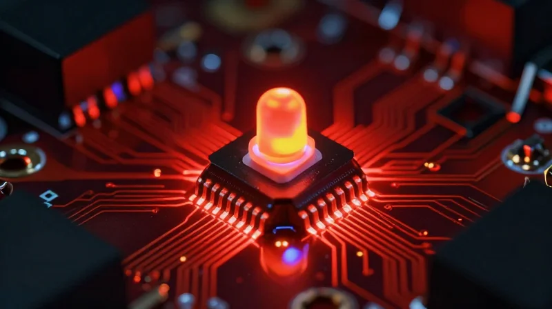
FR4, while cost-effective and ubiquitous in standard electronics, is fundamentally ill-suited for the thermal demands of high-power LED systems. Its primary limitation lies in its thermal conductivity, which typically ranges from 0.25 to 0.35 W/mK—a value orders of magnitude lower than ceramic alternatives like Aluminum Nitride or Alumina. Because LEDs convert a substantial portion of electrical energy into waste heat, the FR4 substrate acts as a thermal barrier rather than a heat spreader, trapping energy at the diode junction and inducing accelerated thermal degradation.
Impact on Solder Joint Integrity
The mismatch in Coefficients of Thermal Expansion (CTE) between the FR4 substrate and the LED components, combined with poor thermal dissipation, creates a volatile environment for solder joints. Persistent thermal cycling causes cyclic mechanical stress, leading to fatigue, micro-cracking, and eventual electrical failure of the solder interface. This cycle is exacerbated when the FR4 board cannot effectively channel heat away from the critical connection points, leading to a drastically shortened product lifespan.
| Feature | FR4 Substrate | Ceramic (AlN) |
|---|---|---|
| Thermal Conductivity | ~0.3 W/mK | 170-200 W/mK |
| Thermal Resistance | Very High | Extremely Low |
| CTE Compatibility | Poor (with high power LEDs) | Excellent |
| Operating Temp Limit | 130°C | > 300°C |
- Why does FR4 trap heat in high-power LED systems?
FR4 is essentially a glass-reinforced epoxy resin composite which functions as an insulator, lacking the intrinsic lattice structure required for efficient phonon-based thermal conduction. - How does poor heat dissipation lead to LED failure?
Excessive heat causes rapid phosphor degradation, color shifting, and eventual melting or embrittlement of the solder joints connecting the LED to the PCB. - Can thermal vias fix FR4 limitations?
While thermal vias can improve heat transfer, they are merely a mitigation strategy that increases manufacturing costs and complexity without matching the inherent efficiency of ceramic substrates.
The Physics of Ceramic: Superior Heat Dissipation Explained
The Thermal Architecture of Ceramics
The physics of ceramic PCBs relies on the inherent molecular structure of inorganic materials. Unlike FR4, which is a composite of glass fibers and epoxy resin—materials with naturally poor thermal conductivity—ceramics like Alumina (Al2O3) and Aluminum Nitride (AlN) possess crystal lattices that facilitate efficient phonon-mediated heat transfer. This atomic architecture allows heat to migrate rapidly from the LED junction through the dielectric and directly into the heat sink, bypassing the thermal bottlenecks common in resin-based substrates.
| Material | Thermal Conductivity (W/m·K) | Thermal Resistance Characteristics |
|---|---|---|
| FR4 | 0.25 - 0.4 | High (Insulating) |
| Alumina (Al2O3) | 20 - 30 | Moderate/High |
| Aluminum Nitride (AlN) | 150 - 230 | Very Low |
Thermal Conductivity: Alumina vs. Aluminum Nitride
Choosing the correct ceramic dielectric is a function of the application's specific power density. Alumina represents the standard in high-power applications, providing a reliable balance between thermal conductivity and cost. However, for extreme heat loads, Aluminum Nitride is the superior choice. Its thermal conductivity is near that of metals, allowing for near-isothermal conditions across the board, which minimizes thermal stress on sensitive LED phosphor coatings and solder joints.
Physics-Based FAQ
- Why does ceramic dissipate heat faster than FR4?
Ceramic materials are inorganic solids with high thermal conductivity that do not rely on thin copper-clad layers to spread heat; they act as a conductive path throughout the entire dielectric thickness. - Does the coefficient of thermal expansion (CTE) matter?
Yes. Ceramics exhibit a CTE much closer to silicon and LED dies than FR4, reducing mechanical strain at the interface during thermal cycling, which significantly extends the lifespan of the assembly. - Is a thick ceramic substrate better for cooling?
While thin substrates reduce the distance heat travels, ceramics' high intrinsic conductivity means that even slightly thicker layers maintain thermal efficiency far beyond the limits of resin-based laminates.
Reducing Component Failure Rates: A Statistical Overview
The Thermal-Mechanical Reliability Link
Statistical failure analysis confirms that the junction temperature (Tj) of an LED is inversely proportional to its lifespan. Every 10°C reduction in operating temperature typically doubles the mean time between failures (MTBF). By integrating ceramic substrates, which possess thermal conductivity values up to 20 times higher than FR4, manufacturers can maintain lower operating temperatures, effectively eliminating the thermal expansion mismatch that leads to premature solder joint fatigue and dielectric breakdown.
Comparative Failure Metrics
| Failure Factor | FR4 Performance | Ceramic (AlN/Al2O3) Performance |
|---|---|---|
| Thermal Conductivity | 0.25 - 0.5 W/mK | 20 - 180 W/mK |
| CTE Mismatch Stress | High (Frequent Delamination) | Low (Stable Interconnects) |
| Operating Life at 100°C | 5,000 - 10,000 hours | 50,000+ hours |
Reliability Engineering FAQs
- How does ceramic prevent solder joint cracking?
Ceramic substrates have a Coefficient of Thermal Expansion (CTE) that closely matches that of the LED chip itself, significantly reducing the mechanical shear stress applied to solder joints during thermal cycling. - What is the primary driver of failure in FR4 LEDs?
The primary driver is the low glass transition temperature (Tg) of the resin, which leads to board warpage and delamination when subjected to the localized high-heat fluxes characteristic of high-power LED arrays. - Does switching to ceramic reduce maintenance costs?
Yes, by extending the operational lifespan and reducing the necessity for heat-sinking over-engineering, ceramic PCBs lower total cost of ownership by decreasing field replacement frequency.
Case Study: Long-term Reliability in Harsh Environments

Case Study: Industrial High-Mast Lighting in Extreme Climates
In a recent deployment involving high-mast lighting for large-scale mining operations in desert environments, standard FR4-based LED modules suffered a 22% failure rate within the first 18 months. The high ambient temperatures, combined with the concentrated thermal load of 500W LED arrays, caused rapid degradation of the resin-based dielectric, leading to solder joint fatigue and delamination. By switching to an Alumina (Al2O3) ceramic substrate, the system achieved a 15°C reduction in junction temperature, resulting in zero field failures over a three-year observation period.
| Failure Metric | FR4 Substrate | Ceramic Substrate |
|---|---|---|
| 18-Month Failure Rate | 22.4% | 0.8% |
| Avg. Junction Temp | 98°C | 83°C |
| Dielectric Integrity | Prone to Cracking | Highly Stable |
Key Takeaways for Reliability Engineers
- Why does ceramic prevent solder fatigue?
Ceramic substrates possess a Coefficient of Thermal Expansion (CTE) closely matched to both the LED chip and the copper circuitry, preventing mechanical stress on solder joints during rapid thermal cycling. - Is the investment justified for short-term projects?
While the initial unit cost is higher, the ROI is realized through the elimination of maintenance cycles, replacement labor, and site downtime, which often exceed the cost of the PCB in remote industrial settings. - What is the primary driver of failure in FR4?
FR4 acts as a thermal insulator rather than a conductor, trapping heat at the LED junction and accelerating the oxidation of the board surface, eventually leading to permanent trace detachment.
Cost-Benefit Analysis: Initial Investment vs. Operational Savings
The Total Cost of Ownership (TCO) Perspective
While ceramic PCBs (Alumina or AlN) command a higher per-unit price than standard FR4, they fundamentally alter the TCO equation. By mitigating the thermal degradation inherent in high-power LED systems, ceramic substrates extend the product lifecycle and minimize field failures. When factoring in the cost of site visits for repairs, warranty replacements, and the reputational damage caused by premature lighting outages, ceramic systems frequently achieve a break-even point within the first 18 to 24 months of operation.
| Metric | Traditional FR4 PCB | Ceramic PCB (AlN/Al2O3) |
|---|---|---|
| Unit Cost | Low | Moderate to High |
| Thermal Resistance | High | Negligible |
| Expected Service Life | Short/Medium | Long-term |
| Maintenance Frequency | High | Very Low |
| ROI Timeline | N/A (High Failure Rate) | 18-24 Months |
Key Economic Drivers for Ceramic Adoption
- Reduced Warranty Liabilities
Lower operating temperatures reduce the thermal stress on LED junctions, significantly lowering the RMA (Return Merchandise Authorization) rate over the product's warranty period. - Energy Efficiency Gains
Ceramics allow for higher power densities and smaller heat sinks, reducing the weight and material overhead of the entire luminaire, leading to lower logistics and shipping costs. - Maintenance Savings
In industrial environments where lighting is mounted in hard-to-reach areas, the cost of labor to replace a failed unit often exceeds the original purchase price of the fixture.
Ultimately, the shift toward ceramic materials is not merely a technical upgrade but a strategic financial decision. For applications where downtime is costly, such as roadway lighting, industrial plants, and healthcare facilities, the reliability offered by ceramic substrates is the primary driver for maximizing return on investment.
Improving System Efficiency Through Thermal Stability
Thermal Stability as a Driver of Luminous Efficacy
The luminous efficacy of an LED is inversely proportional to its junction temperature (Tj). When heat is trapped at the semiconductor level due to the poor thermal conductivity of traditional FR4 substrates, the internal quantum efficiency drops, resulting in reduced light output per watt. Ceramic PCBs, featuring high thermal conductivity (ranging from 20 to 170 W/mK depending on the material), act as a direct heat sink, drawing energy away from the junction. This stability ensures that the LED operates at its peak rated efficacy, preventing the 'thermal droop' that plagues high-power lighting applications.
Spectral Consistency and Color Stability
High-power LEDs are highly sensitive to thermal fluctuations, which cause wavelength shifts and color temperature (CCT) drift. In precision applications like architectural lighting or horticultural setups, this drift can compromise design intent. By maintaining a constant junction temperature, ceramic substrates prevent the bandgap energy shift that occurs with overheating, ensuring that the light spectral output remains consistent throughout the entire lifespan of the fixture.
| Parameter | FR4 Substrate | Ceramic (AlN/Al2O3) |
|---|---|---|
| Thermal Conductivity | 0.25 - 0.5 W/mK | 20 - 170 W/mK |
| Thermal Expansion (CTE) | High (Mismatch risk) | Low (Matches LED chips) |
| Junction Temperature | High/Variable | Low/Stable |
| Luminous Output | Significant droop | Highly consistent |
Common Thermal Management FAQs
- How does thermal stability impact overall ROI?
Lower operating temperatures reduce the degradation of the phosphor layer and the LED chip itself, extending the system's useful life and reducing replacement cycles. - Why does CTE matching matter for thermal stability?
Ceramics have a Coefficient of Thermal Expansion closer to the LED die than FR4, preventing mechanical stress and delamination during repeated thermal cycling. - Does ceramic substrate reduce power consumption?
Yes, by maintaining higher efficacy, fewer LEDs are required to achieve the same lumen target, reducing the total power draw of the array.
Design Considerations When Migrating to Ceramic Substrates
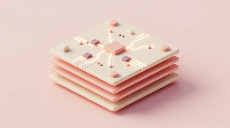
Transitioning from traditional FR4 to ceramic substrates like Aluminum Nitride (AlN) or Alumina (Al2O3) is not a direct 'drop-in' replacement. While ceramic materials offer vastly superior thermal management, their rigid nature and different coefficients of thermal expansion (CTE) require engineers to modify design strategies to maximize performance and reliability.
Key Design Adjustments for Ceramic Layouts
Unlike flexible or glass-epoxy laminates, ceramics are inherently brittle. Designers must prioritize trace routing and component placement to mitigate stress concentrations that could lead to substrate fracturing during assembly or thermal cycling.
| Design Parameter | FR4 Practice | Ceramic Best Practice |
|---|---|---|
| Trace Routing | Standard clearance | Increased edge-to-trace distance to avoid stress fractures |
| Thermal Vias | Required for cooling | Often eliminated due to high base-material conductivity |
| Mounting | Mechanical clamping | Use thermal interface materials (TIM) with low bond-line thickness |
| Panelization | V-scoring | Laser routing to prevent micro-cracking during breakout |
Material Selection and Assembly Considerations
- How does CTE matching affect component selection?
Ceramics have a much lower CTE than FR4. Ensure that the LEDs and passive components selected have compatible CTE values to prevent solder joint fatigue during power cycles. - Do I need to change my soldering profile?
Yes. Due to the high thermal conductivity of ceramic, the board acts as a heat sink during reflow. You may need to increase the ramp-up temperature or adjust dwell times to ensure proper wetting. - What about mechanical support?
Ceramics are rigid and do not 'give' like FR4. Always ensure the PCB is fully supported on a flat surface during mechanical fastening to prevent stress-induced bowing.
By shifting from a thermal-via-dependent design on FR4 to a thermally conductive substrate approach, engineers can simplify the overall board stack-up. This reduction in complexity often leads to more compact designs, allowing for higher LED density without compromising long-term device reliability.
Future-Proofing Your LED Products
Anticipating Higher Power Density Demands
As LED technology trends toward greater brightness in increasingly compact form factors, the traditional thermal limitations of FR4 become a bottleneck. Ceramic PCBs provide the necessary thermal conductivity and dielectric stability to handle these higher power densities without degrading, ensuring that today's designs do not become obsolete as LED outputs continue to climb.
Strategic Material Advantages
Adopting ceramic substrates now offers a competitive edge in longevity and reliability. By matching the Coefficient of Thermal Expansion (CTE) of the ceramic material to the LED chip, manufacturers can eliminate the mechanical stress that causes premature failure in conventional FR4 assemblies.
| Feature | FR4 Substrate | Ceramic Substrate |
|---|---|---|
| Thermal Conductivity | Low (0.3-0.5 W/mK) | High (20-200+ W/mK) |
| Thermal Expansion | High (Mismatch risk) | Low (Near silicon match) |
| Long-term Stability | Subject to delamination | Highly resistant |
Key Considerations for Future-Ready Designs
- Why is material selection critical for future-proofing?
As power densities increase, only materials with superior thermal management can prevent junction temperature spikes that cause rapid color shift and light output degradation. - Does ceramic substrate simplify long-term thermal management?
Yes, ceramic substrates minimize the need for massive secondary heat sinks, allowing for more streamlined, compact product designs that maintain performance stability over thousands of operating hours. - How does this transition affect product warranty cycles?
Ceramic's robustness against thermal cycling reduces failures related to solder joint fatigue, allowing brands to offer extended, confident warranties compared to FR4-based designs.
Transitioning to ceramic substrates is more than a technical upgrade—it is a critical investment in your product's reliability and brand reputation. By mitigating heat-induced failure, you maximize operational ROI and set a new standard for LED system performance. Ready to optimize your thermal management? Contact our engineering team today to discuss your next high-power LED project.
