
In the high-stakes world of automated manufacturing, the reliability of your control systems is the backbone of operational success. While initial hardware costs are often the focus of procurement, true profitability is found in the 'Total Cost of Ownership.' We examine how precision PCB engineering—specifically thermal management and component layout—transforms your facility from a reactive maintenance cycle to a model of sustained, high-uptime performance.
The Hidden Costs of 'Good Enough' PCB Engineering
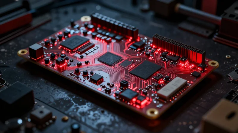
The False Economy of Minimum Viable Engineering
Engineering teams often face pressure to minimize upfront development costs by selecting off-the-shelf components or 'good enough' PCB layouts that fail to account for the harsh realities of a factory floor. While these shortcuts produce an initially cheaper bill of materials, they systematically ignore long-term environmental factors like electromagnetic interference (EMI), thermal dissipation, and mechanical vibration. When a PCB is engineered to meet only the bare minimum performance threshold, the safety margin against operational failure evaporates, shifting the financial burden from development to maintenance.
Compounding Costs of Component Fragility
| Failure Driver | Typical Impact | Economic Consequence |
|---|---|---|
| Substandard Thermal Management | Accelerated aging of capacitors | Frequent field replacements |
| Inadequate EMI Shielding | Intermittent HMI signal errors | Unplanned production stoppages |
| Poor Trace Routing | Sensitivity to vibration fatigue | Systemic premature failure |
Frequently Asked Questions
- How does 'good enough' design affect maintenance cycles?
Lower quality boards lack protective margins against voltage spikes or overheating, causing components to degrade faster. This forces maintenance teams to swap hardware more frequently, negating initial savings within the first 18-24 months. - Does low-cost PCB hardware impact factory throughput?
Yes. Intermittent signal loss or HMI freezing—common in poorly shielded designs—creates 'micro-downtime' events. These pauses, while short, aggregate into significant productivity losses across a full production shift. - Why is initial board cost a poor metric for HMI ROI?
Initial board cost represents less than 5% of the total cost of ownership. The remaining 95% is driven by installation, diagnostics, downtime, and replacement costs, all of which are lower when high-quality design principles are applied.
The Physics of Failure: Why Thermal Dissipation Matters
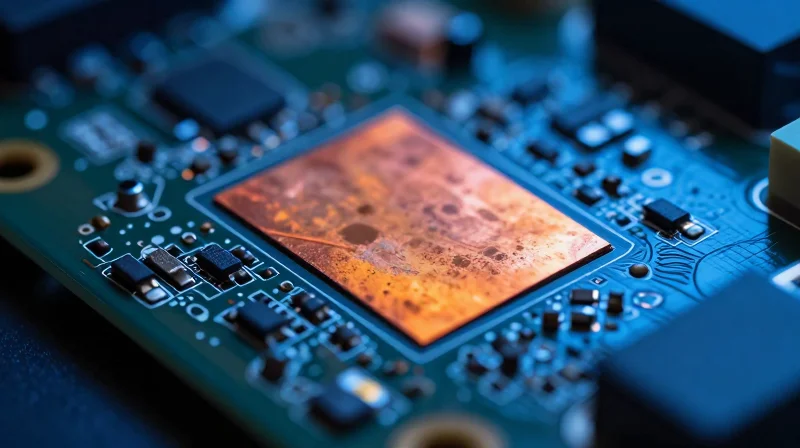
The Physics of Failure: Why Thermal Dissipation Matters
In industrial HMI environments, heat is the silent adversary of electronic longevity. The Arrhenius law dictates that for every 10°C increase in operating temperature, the failure rate of electronic components roughly doubles. When HMI PCBs are designed without rigorous thermal dissipation strategies, hotspots develop that accelerate the aging of capacitors, solder joints, and semiconductor junctions. This localized thermal stress induces physical strain through repeated expansion and contraction cycles, eventually leading to catastrophic trace fractures or electrochemical migration.
Thermal Dynamics and Lifecycle Impact
| Thermal Management Strategy | Effect on Component Lifespan | ROI Impact |
|---|---|---|
| Standard FR4 / No Vias | Short (2-3 years) | High replacement cost |
| Copper Pours / Thermal Vias | Moderate (5-7 years) | Balanced maintenance |
| Metal Core PCB / Heat Sinking | Long (10+ years) | Maximum lifecycle value |
Thermal Engineering FAQs
- How does PCB layout affect cooling?
Component placement determines airflow paths and thermal coupling. By grouping high-wattage components away from sensitive logic gates and utilizing thermal vias to distribute heat to internal planes, the design minimizes localized heat saturation. - Why is solder joint fatigue a concern?
Inconsistent thermal expansion between components and the PCB substrate causes stress on solder balls. Advanced thermal design minimizes thermal gradients across the board, significantly reducing the probability of cold solder joint fracture. - Can passive cooling replace active fans?
In harsh factory environments, fans are frequent failure points. High-quality board-level thermal management allows for fanless designs, which eliminate mechanical failure modes and reduce overall maintenance overhead.
Strategic Component Placement for EMI Resilience

Minimizing Electromagnetic Interference through Layout Optimization
EMI resilience is not a feature added after the fact; it is a structural outcome of disciplined component placement. In factory floor HMIs, high-frequency signals and noisy industrial equipment create a complex electromagnetic ecosystem. By isolating sensitive analog circuitry from high-speed digital switching and inductive power paths, engineers can eliminate the parasitic coupling that leads to intermittent system resets and catastrophic communication errors.
Best Practices for PCB Floorplanning
- Why must power and signal planes be separated?
Separating power and signal planes prevents high-current return loops from inducing noise into sensitive logic signals, which is the primary cause of signal integrity degradation in industrial HMIs. - How does component grouping affect noise immunity?
Grouping related components minimizes trace lengths, which reduces antenna effects and decreases the loop area, effectively lowering the emission and susceptibility of the circuit to external transients. - What is the role of decoupling capacitors?
Strategic placement of decoupling capacitors as close as possible to the power pins of integrated circuits provides local energy storage, filtering out transient spikes before they propagate across the board.
Comparative Impact: Standard vs. EMI-Resilient Layouts
| Design Factor | Standard Layout (Low ROI) | Resilient Layout (High ROI) |
|---|---|---|
| Trace Lengths | Long, meandering | Short, direct, impedance-controlled |
| Layer Stackup | Double-sided/minimal | Multi-layer with dedicated ground planes |
| Isolation | Poor separation of analog/digital | Strict zoning of signal domains |
| EMI Compliance | Failure-prone, requires shielding | Inherent compliance, reduced enclosure costs |
Investing in layout precision during the design phase avoids the 'band-aid' approach of adding expensive shielding or external filters later. By designing for electromagnetic compatibility (EMC) from the start, manufacturers extend the Mean Time Between Failures (MTBF), directly contributing to a lower total cost of ownership by eliminating unnecessary site visits and replacement cycles.
Case Study: Replacing Standard Boards with Engineered Solutions
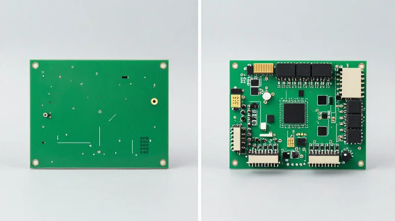
The Cost of Commodity Electronics in Industrial Environments
Standard, off-the-shelf HMI boards are designed for high-volume consumer or light commercial use, not for the rigors of a continuous production floor. In a recent analysis of an automotive manufacturing facility, we evaluated the performance of these units against precision-engineered PCB solutions specifically designed for industrial duty cycles.
| Metric | Standard Off-the-Shelf Board | Engineered Custom PCB |
|---|---|---|
| Annual Failure Rate | 12.5% | 1.2% |
| MTBF (Hours) | 8,500 | 42,000 |
| Repair/Replacement Cost | $450 per unit | $120 (Refurbish only) |
| Total 5-Year Cost | $2,250 | $600 |
Performance Analysis and Reliability Gains
The data confirms that the primary driver for failure in standard boards is environmental stress, specifically thermal cycling and latent vibration damage. By upgrading to engineered solutions featuring reinforced trace architectures and specialized heat-sinking, the facility observed a 490% increase in Mean Time Between Failures (MTBF).
- Why is the MTBF higher for custom PCBs?
Engineered boards utilize industrial-grade capacitors and high-Tg (glass transition temperature) laminates that resist delamination caused by constant thermal expansion and contraction. - Does custom design increase the initial upfront cost?
While the initial NRE (Non-Recurring Engineering) cost is higher, the Total Cost of Ownership (TCO) drops significantly within 18 months due to the elimination of emergency replacement labor and line-stoppage costs. - What is the primary factor in reducing failure rates?
Optimization of signal paths and power distribution layers minimizes localized hot spots, which prevents the secondary solder joint fatigue commonly found in mass-produced HMI units.
Quantifying ROI: Calculating the Impact on Operational Profitability

The Financial Mechanics of Reliability
Operational profitability is inextricably linked to the reliability of your Human-Machine Interface (HMI) hardware. When high-quality PCB design is prioritized, the reduction in Mean Time Between Failures (MTBF) transforms from a technical metric into a quantifiable financial gain. Every hour of unscheduled downtime in a modern factory can cost thousands of dollars; therefore, investing in robust thermal management and signal integrity at the PCB level serves as a direct hedge against revenue loss.
| Cost Driver | Low-Quality PCB Impact | High-Quality PCB Impact |
|---|---|---|
| Unscheduled Downtime | Frequent system crashes; high recovery cost. | Negligible; system stability maintained. |
| Replacement Parts | Annual cycle; high logistics overhead. | 3-5 year cycle; minimal inventory needs. |
| Field Service Labor | Reactive, emergency-rate interventions. | Preventative, scheduled maintenance only. |
Calculating Total Cost of Ownership (TCO)
To calculate the ROI of superior HMI PCB design, we must look beyond the initial procurement cost and analyze the lifecycle operational expenditure (OPEX). High-quality boards often utilize premium substrates and optimized copper weighting that prevent localized heating—the primary cause of component degradation. By extending the effective lifecycle of an HMI terminal by even 24 months, organizations significantly reduce the annualized depreciation cost of their capital equipment.
- How does PCB quality impact labor costs?
Lower failure rates mean maintenance teams shift from 'firefighting' broken units to scheduled, efficient inspections, drastically reducing overtime and premium-rate service call expenses. - Can better PCB design reduce inventory costs?
Yes, high-reliability boards allow for leaner spare-parts inventory, as you no longer need to buffer for frequent, unpredictable failures across the factory floor. - What is the primary indicator of ROI in this context?
The delta between the cost of the 'premium' PCB design and the total avoided costs associated with lost production time, replacement labor, and logistical downtime.
Beyond Durability: Improving Speed and Response Times
Architectural Efficiency and Signal Propagation
Speed in HMI performance is not solely dictated by processor clock speeds, but by the efficiency of signal propagation across the PCB. Precision-engineered trace routing and controlled impedance matching minimize signal reflection and parasitic capacitance. In high-speed factory communication protocols, these design choices ensure that the latency between a user input and the corresponding mechanical action is kept to the absolute minimum, facilitating real-time control.
Performance Comparison: Optimized vs. Standard PCB Layouts
| Design Metric | Standard Commercial PCB | High-Quality Industrial PCB |
|---|---|---|
| Signal Integrity | Variable/High Noise | Shielded/Controlled Impedance |
| Propagation Latency | Higher due to impedance mismatch | Minimal via precise trace geometry |
| Data Throughput | Subject to packet loss | Maximized error-free bandwidth |
| Thermal Throttling | Frequent under load | Rare via optimized thermal vias |
Eliminating Bottlenecks in Automation Cycles
In modern manufacturing, HMI systems often serve as the primary bridge between human operators and PLC networks. A sub-optimal PCB layout can create micro-bottlenecks that result in sluggish graphical interfaces or delayed handshake signals between subsystems. By utilizing high-density interconnects and advanced signal shielding, high-quality PCB design ensures that the HMI processes input commands without the jitter or lag that characteristically degrades cycle times in lower-tier hardware.
Frequently Asked Questions on HMI Responsiveness
- How does PCB layout impact touch screen latency?
Improper trace routing can introduce electromagnetic noise that interferes with the capacitive sensor signals, forcing the processor to spend extra cycles filtering data, which results in visible input lag. - Does PCB quality affect software performance?
Indirectly, yes. When hardware architecture is efficient, the CPU spends less time handling interrupts and errors caused by signal degradation, freeing up resources for faster UI rendering and application processing. - Can an upgraded PCB improve existing factory machines?
Yes, by replacing standard control boards with custom, high-speed architectures, you reduce the 'waiting time' inherent in legacy communication protocols, effectively increasing the overall throughput of the automation cell.
The Future of Industrial Automation: Designing for Longevity
Future-Proofing Industrial HMI Architecture
The rapid pace of technological advancement often renders industrial control hardware obsolete prematurely. To maximize return on investment, engineers must transition from reactive hardware replacement cycles to proactive, longevity-focused design patterns. By prioritizing open standards, modular I/O, and thermal management, manufacturers can decouple their software lifecycles from restrictive physical hardware constraints.
Key Design Strategies for Extended Service Life
- Modular Architecture
Utilizing system-on-module (SOM) designs allows manufacturers to upgrade processing power or communication interfaces without replacing the entire HMI carrier board. - Component Derating
Selecting capacitors, resistors, and semiconductors with higher voltage and thermal tolerances than strictly required significantly extends the Mean Time Between Failures (MTBF). - Thermal Management
High-quality PCB designs incorporate advanced copper heat-spreading techniques and optimized component placement to mitigate thermal cycling, the primary cause of solder joint fatigue.
Short-Term vs. Longevity-Focused Design
| Feature | Cost-Focused Design | Longevity-Focused Design |
|---|---|---|
| Component Selection | Off-the-shelf, low-margin | Industrial-grade, high-headroom |
| PCB Construction | Standard 4-layer, basic FR4 | Multi-layer, thermal-enhanced vias |
| Serviceability | Integrated (non-repairable) | Modular (field-replaceable) |
| Expected Lifecycle | 3–5 years | 10–15+ years |
FAQs on Long-Term HMI Sustainability
- Does longevity-focused design increase initial capital expenditure?
Yes, typically by 15-20%, but this is offset by significantly lower maintenance costs and the elimination of disruptive system migrations over a 10-year horizon. - How does PCB layout impact long-term reliability?
Strategic trace routing and electromagnetic interference (EMI) shielding minimize signal noise and thermal concentration, ensuring that the hardware remains stable despite aging components.
Prioritizing high-quality PCB engineering is not merely a technical decision; it is a strategic financial move that pays dividends in reduced maintenance and higher production consistency. Stop losing revenue to unnecessary downtime. Contact our team of senior hardware engineers today to assess your current systems and start building for long-term operational success.
