
In the high-stakes world of hardware development, the transition from prototype to high-volume production is where most projects stumble. Achieving high-precision assembly requires more than just skilled technicians; it demands a synergy between rigorous Design for Manufacturing (DFM) principles and meticulous mechanical integration. In this guide, we dissect the technical workflow necessary to eliminate assembly-line friction and ensure your final product meets the highest standards of reliability.
The Foundation: Integrating DFM Early in the Product Lifecycle

The Economic Imperative of Early DFM Intervention
The decision to integrate DFM at the conceptual phase is a strategic buffer against the compounding costs of technical rework. In the context of turnkey box builds—which encompass everything from PCB assembly and wiring harnesses to mechanical chassis integration—the complexity of assembly and supply chain alignment is immense. When DFM principles are deferred, engineers risk 'locking in' designs that are inherently difficult to assemble, test, or scale, leading to linear increases in manufacturing latency and unit costs.
| Development Stage | Cost of Change | DFM Impact Potential |
|---|---|---|
| Conceptual Design | 1x | High (Architecture level) |
| Prototyping | 10x | Medium (Assembly optimization) |
| Full Production | 100x+ | Low (Marginal efficiency gains) |
Common Pitfalls and Mitigation Strategies
- Why do many firms delay DFM until the prototype phase?
Organizations often prioritize time-to-market speed over process maturity, erroneously believing that DFM analysis slows down the initial CAD design phase rather than enabling it. - What is the primary risk of late-stage DFM integration in box builds?
Late-stage DFM often reveals mechanical interferences or cabling accessibility issues that necessitate complete redesigns of the chassis or PCB layout, effectively nullifying previous validation efforts. - How does early DFM influence supply chain resilience?
Early engagement allows for the selection of common-stock components and standardized hardware, which stabilizes lead times and provides flexibility during global material shortages.
Bridging Design Intent with Manufacturing Reality
Successful turnkey box build engineering requires a collaborative environment where manufacturing feedback loops are active from the first schematic review. By utilizing virtual build simulations and design rule checks (DRC) during the layout phase, engineers can ensure that tolerance stacks, thermal management requirements, and interconnect accessibility are optimized before the first physical prototype is ever ordered. This proactive stance transforms DFM from a checking procedure into a core component of precision systems engineering.
Standardizing Sub-Assembly Testing Protocols

The Architecture of Pre-Integration Validation
Standardization of sub-assembly testing is the technical firewall against final-assembly bottlenecking. By implementing rigorous gate-keeping protocols at the sub-assembly level—typically encompassing PCBA functional testing, cable harness continuity checks, and mechanical fitment audits—engineers can isolate defects before they propagate into the complex, high-cost environment of a fully enclosed turnkey unit.
Comparative Analysis of Validation Methodologies
| Testing Protocol | Primary Objective | DFM Impact |
|---|---|---|
| In-Circuit Testing (ICT) | Verify electrical component placement | High initial cost, rapid fault identification |
| Functional Testing (FCT) | Validate system-level performance | Essential for high-mix/low-volume agility |
| Automated Optical Inspection (AOI) | Detect soldering and physical defects | Reduces downstream rework cycles |
Key Questions for Protocol Development
- How do we define test coverage for modular components?
Coverage should be determined by a Failure Mode and Effects Analysis (FMEA), ensuring that any sub-assembly that could cause a critical failure in the final box build is subjected to automated functional verification. - At what stage should mechanical fitment testing occur?
Mechanical tolerances should be validated using 'Go/No-Go' gauging prior to final torque application in the chassis to prevent unnecessary labor costs associated with teardowns. - Why is data serialization critical to sub-assembly testing?
Serialization allows for granular traceability. If a final box build fails during final QA, data logs can pinpoint whether the root cause originated from a specific sub-assembly batch, facilitating surgical recall rather than total product scrap.
Maintaining a robust test protocol requires strict adherence to standardized test jigs and calibrated software fixtures. In turnkey environments, engineers must treat the test fixture itself as a precision instrument, ensuring repeatability across distributed manufacturing sites to maintain high first-pass yields (FPY).
Precision Alignment and Mechanical Tolerance Analysis
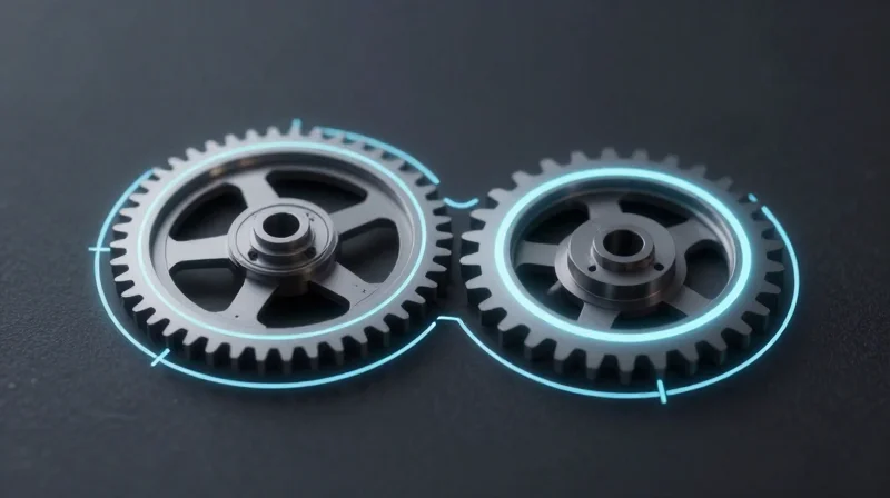
Managing Cumulative Tolerance Stack-Ups
Precision alignment in turnkey box builds relies on rigorous control of cumulative tolerance stack-ups. When individual component variations interact within an enclosure, they often amplify, leading to interference, binding, or gaps that compromise both structural integrity and aesthetic finish. Engineers must employ Worst-Case Analysis (WCA) for critical interface points and Root Sum Squared (RSS) statistical modeling for non-critical features to balance manufacturing yield with functional precision.
Comparison of Tolerance Analysis Methodologies
| Methodology | Risk Assessment | Cost/Complexity | Best Use Case |
|---|---|---|---|
| Worst-Case (WCA) | High (Conservative) | Low | Interlocking safety features |
| RSS (Statistical) | Moderate (Realistic) | High | General assembly fitment |
| Monte Carlo Simulation | Comprehensive | Highest | Complex kinematic linkages |
Strategic DFM Guidelines for Mechanical Integration
To achieve seamless integration, DFM strategies must move beyond individual part tolerances to focus on datum alignment. Establishing primary, secondary, and tertiary datums that carry through from the PCB to the chassis is essential. By utilizing self-aligning features—such as tapered dowel pins or floating fastener hardware—manufacturers can accommodate minor variations without necessitating prohibitively expensive precision machining across all components.
Frequently Asked Questions
- How do floating fasteners mitigate tolerance issues?
Floating fasteners provide a compensatory range, allowing for minor positional offsets in mounting holes without inducing internal stress on the assembly. - When is Statistical Tolerance Analysis preferred over Worst-Case?
Statistical analysis is preferred when the manufacturing process is highly stable (high Cpk) and the cost of forcing absolute precision exceeds the risk of occasional rework. - Why should datums be shared across components?
Shared datums minimize errors caused by frame-of-reference shifts, ensuring that parts align based on the same origin points throughout the build process.
Wiring and Cable Management Strategies for High-Density Builds

Strategic Routing and Signal Integrity
In high-density enclosures, the proximity of signal lines to power delivery systems creates significant electromagnetic interference (EMI) risks. Designers must implement a hierarchical routing strategy that separates low-voltage signal paths from high-current power runs. Using twisted-pair configurations for data lines and shielding high-speed interfaces are essential to minimize crosstalk and preserve signal fidelity. Furthermore, defining routing paths during the mechanical design phase—rather than as an assembly-time afterthought—ensures that cables do not impede airflow or obstruct critical mounting points.
Material Selection and Management Techniques
| Management Method | Primary Benefit | Best Use Case |
|---|---|---|
| Braided Sleeving | Abrasion Resistance | Dynamic or moving parts |
| Spiral Wrap | Flexibility/Expansion | Branching cable bundles |
| Adhesive-Backed Clips | Space Optimization | Internal walls/Compact areas |
| Custom Cable Trays | Structural Organization | Large-scale modular builds |
Best Practices for Strain Relief and Durability
Mechanical failure at connector interfaces is the most common cause of field returns in dense assemblies. Implementing robust strain relief mechanisms prevents cable fatigue and minimizes stress on solder joints or PCB headers. Designers should prioritize 'service loop' inclusion—providing extra cable slack to facilitate assembly and prevent tension—while utilizing bulkhead connectors to transfer mechanical loads directly to the chassis rather than the internal electronics.
Frequently Asked Questions
- How can I prevent cable congestion from restricting airflow?
Utilize thin-gauge ribbon cables where possible and secure bundles against enclosure sidewalls using low-profile routing channels. Ensure all cable paths are mapped in the 3D CAD model to verify clearances. - What is the industry standard for securing connectors in high-vibration environments?
Apply secondary retention methods such as RTV silicone, cable ties with locking bases, or mechanical strain relief clamps to ensure connections remain seated under mechanical shock. - Why should cable identification be part of the DFM process?
Proper labeling at both ends of each cable reduces assembly time, simplifies troubleshooting, and eliminates rework errors caused by misconnections during the final system integration.
Environmental Sealing and Thermal Management Considerations
Environmental sealing and thermal management represent a critical DFM challenge where physical protection often conflicts with cooling requirements. Engineers must design enclosures that prevent the ingress of contaminants while simultaneously providing effective thermal transfer paths, ensuring system longevity without compromising structural integrity.
Balancing IP Ratings and Thermal Performance
| Requirement | Sealing Strategy | Thermal Impact |
|---|---|---|
| IP54 (Dust/Splash) | Gaskets/Compression Seals | Low resistance to airflow |
| IP65 (Jet Proof) | Sealed Enclosures | Requires heat sinking/conduction |
| IP67 (Immersion) | Hermetic Seals/Potted | Requires active heat pipes or TEC |
Strategic Thermal Design Principles
When sealing demands preclude active airflow, designs must shift toward passive thermal management. High-conductivity paths using Thermal Interface Materials (TIMs) should bridge gaps between localized heat sources and the enclosure chassis, effectively turning the entire outer casing into a heat sink.
- How do I choose the right TIM?
Select based on thermal conductivity, conformability to uneven surfaces, and potential for pump-out over thermal cycling to ensure long-term reliability. - Can I use internal fans in a sealed build?
Yes, internal circulation fans are highly effective at preventing localized hotspots by equalizing internal air temperature, even if the external enclosure remains fully sealed. - What is the role of surface finish in thermal DFM?
High-emissivity coatings (anodization or specific powder coats) significantly improve radiative heat transfer from the external enclosure surfaces to the environment.
DFM Verification
Computational Fluid Dynamics (CFD) analysis should be integrated early in the design phase to predict internal heat dissipation bottlenecks. Furthermore, verify sealing efficacy through rapid prototyping of gasket channels to ensure compression tolerances align with standard assembly variations.
Optimizing Final Enclosure Integration
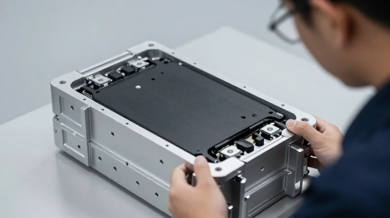
Mastering Final Enclosure Integration
The transition from sub-assembly testing to final enclosure integration is the most critical phase in turnkey box builds. Success here relies on mitigating mechanical stress while maintaining the integrity of sensitive interconnects. By implementing design for manufacturing (DFM) strategies such as pilot-pin alignment, accessible fastening sequences, and localized stress relief, engineering teams can minimize rework and ensure that the final build meets precision specifications under operational loads.
Fastening Protocols and Tolerance Control
Standardized fastening strategies prevent mechanical bias that can warp sensitive boards or misalign optical paths. Utilizing torque-controlled assembly and phased fastening patterns ensures that internal components remain neutral, avoiding unnecessary strain on mounting hardware.
| Method | Best Application | DFM Advantage |
|---|---|---|
| Pilot-Pin Alignment | High-density boards | Eliminates operator error during blind mating |
| Standoff Compression | Ruggedized chassis | Distributes mechanical load across the PCB |
| Captive Fasteners | Field-serviceable units | Prevents hardware loss and simplifies integration |
Frequently Asked Questions: Enclosure Integration
- How can we mitigate vibrational loosening of fasteners?
Utilize pre-applied micro-encapsulated thread lockers or specific locking washers that are rated for the system's operational vibration profile. - Why should enclosure mating surfaces have controlled flatness?
Controlled flatness ensures that thermal interface materials (TIM) maintain uniform thickness, which is vital for effective heat transfer from the internal heatsink to the outer shell. - What is the role of 'design for service' in final assembly?
Designing for service involves ensuring that fasteners are accessible without dismantling secondary sub-assemblies, reducing total repair time and minimizing the risk of damage during maintenance.
Quality Assurance: From Functional Testing to Burn-in
Strategic QA Integration in DFM
Quality assurance in box builds must transcend simple continuity checks; it requires a tiered methodology that validates performance across the entire assembly chain. By designing for testability (DFT) early in the DFM phase, engineers can ensure that internal points are accessible for diagnostic monitoring without compromising the structural or thermal integrity of the finished unit.
Testing Methodology Matrix
| Testing Stage | Primary Objective | Methodology |
|---|---|---|
| Functional Verification | Logic & Signal Integrity | Automated Test Equipment (ATE) |
| Environmental Stress | Thermal Stability | Cycling in Chambers |
| Burn-in Testing | Infant Mortality Removal | Continuous Load Operation |
Burn-in and Real-World Stress Simulation
Burn-in testing is the final barrier against latent manufacturing defects. By subjecting systems to high-load operation while monitoring core voltages and thermal gradients, engineers can trigger 'infant mortality' failures in a controlled environment. The goal is to stabilize the system's behavior before field deployment, ensuring that interconnects and semiconductor components perform reliably under worst-case thermal stress.
- How does DFM affect burn-in feasibility?
Incorporating accessible debug ports and modular power distribution allows for simultaneous testing of multiple units, significantly reducing the throughput bottleneck during long-cycle burn-in sessions. - What is the critical threshold for thermal stress?
Thermal stress must be applied within the component's absolute maximum ratings while maintaining airflow patterns representative of the actual enclosure, ensuring that thermal throttling behaviors are captured during the test phase. - Why is functional testing insufficient alone?
Functional testing validates logic at a snapshot in time; burn-in validates stability over time, exposing transient issues such as marginal solder joints or intermittent cable connections that emerge only under thermal expansion.
Data-Driven Continuous Improvement

The Feedback Loop: Converting Metrics into DFM Evolution
Continuous improvement in DFM is not merely about identifying errors, but about systematically closing the loop between the assembly floor and the engineering design environment. By treating the turnkey assembly process as a data-generation engine, engineering teams can correlate specific design features with recurring production bottlenecks, allowing for iterative, evidence-based optimization of future designs.
| Data Source | Key Metric | DFM Optimization Potential |
|---|---|---|
| AOI/AXI Logs | First-Pass Yield | Refining component clearance and solder stencil apertures |
| Cycle Time Analysis | Touch-time per sub-assembly | Adjusting modularity to reduce manual alignment steps |
| Field Failure Reports | MTBF (Mean Time Between Failures) | Enhancing thermal dissipation paths or structural strain relief |
Implementing a Robust Data Analytics Strategy
To move beyond reactive changes, engineers must implement a structured telemetry system within the box build process. This involves mapping mechanical assembly steps to discrete digital timestamps, enabling the identification of 'hidden' assembly friction—those small, recurring issues that do not result in total failure but do significantly increase cost-of-goods-sold (COGS) through increased labor hours.
Frequently Asked Questions
- How do you distinguish between assembly errors and design-induced issues?
Use variance analysis; if a specific sub-assembly shows consistent failure rates across multiple operators and shifts, the root cause is likely an insufficiently robust DFM constraint rather than a human error. - What is the role of digital twins in this continuous improvement cycle?
Digital twins allow for the virtual simulation of proposed design tweaks based on historical failure data, enabling validation of geometry or material changes before committing to physical prototyping. - How often should DFM models be updated for a mature product?
DFM models should be living documents reviewed quarterly or whenever a change in supply chain, component revision, or manufacturing partner occurs.
Optimizing your assembly process is a continuous commitment to precision, testing, and mechanical excellence. By adhering to these DFM strategies, you can significantly reduce failure rates and improve the overall durability of your hardware. Ready to scale your product with confidence? Contact our engineering team today to discuss your next turnkey box build project.
