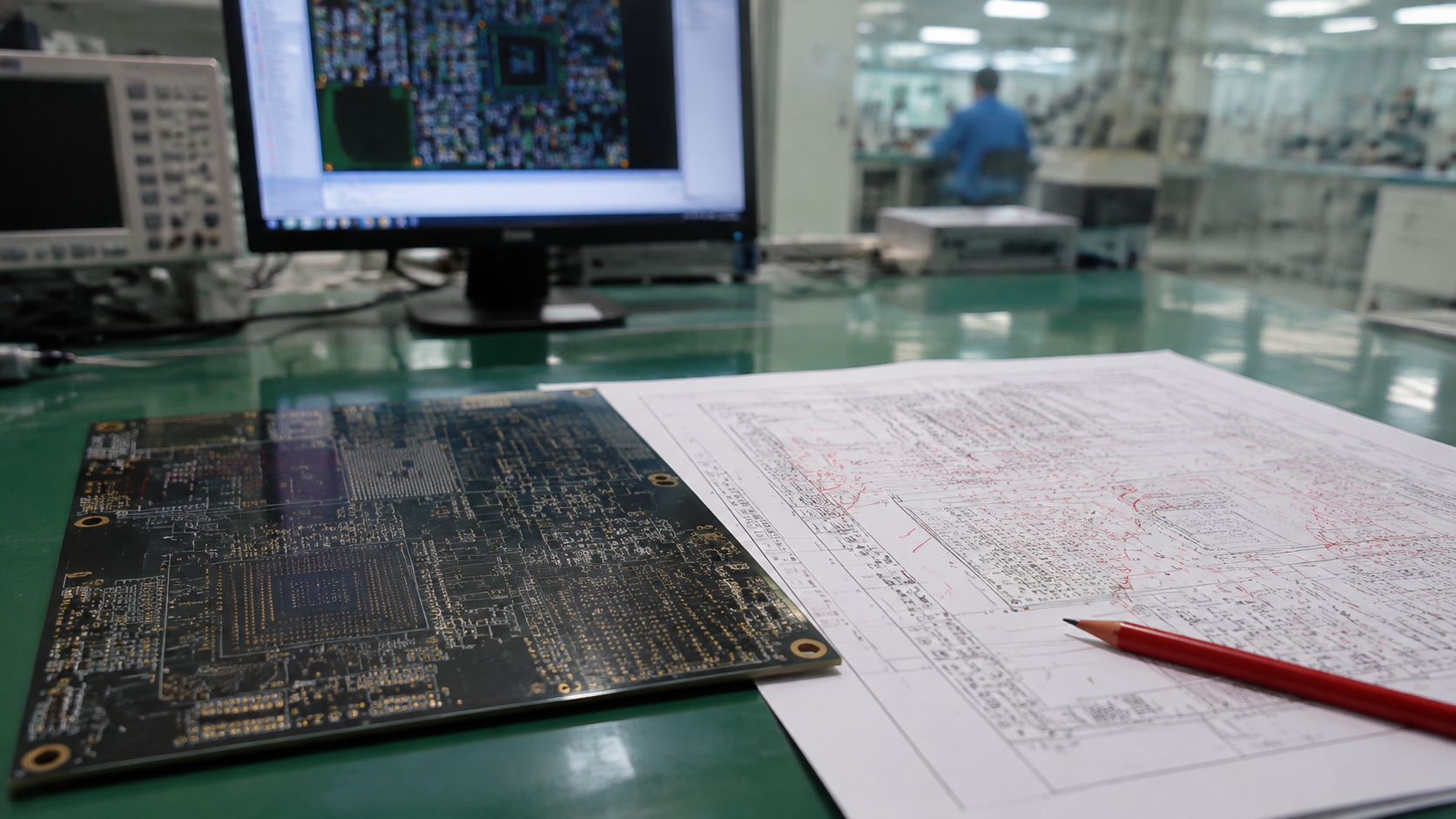
You've spent weeks perfecting your PCB layout. DRC passes with zero errors. You send the Gerber files to your manufacturer with confidence. Then the boards come back — and half of them don't work.
The manufacturer says: "We followed your files." You say: "But my design is perfect."
Both of you are right. And that's exactly the problem.
This is what happens when Design for Manufacturing (DFM) is treated as an afterthought.
DRC checks whether your design follows its own rules. DFM checks whether your design can actually be built. The gap between them is where projects go to die.
Many engineers assume that passing an EDA tool's DRC check means the board is manufacturable. This is a dangerous assumption.
| What DRC Checks | What DFM Checks |
|---|---|
| Electrical rules you set | Factory's physical limits |
| Trace widths and spacing | Etching compensation and tolerances |
| Net connectivity | Drill accuracy and hole quality |
| Your design rules | Solder mask registration and stencil design |
DRC checks your design against your own rules. DFM checks it against physics and process limits.
The difference matters. A design can pass DRC and still fail on the production line — because DRC doesn't know that drilling has mechanical tolerances, or that etching undercuts copper traces, or that your manufacturer's minimum annular ring is different from yours.
Below are the most common DFM issues found during manufacturing reviews — and the design rules that catch them before boards are built.
The Problem: The copper ring around a plated through-hole is too small. Drilling misalignment, registration tolerances, and plating variation can all eat into the annular ring. When it breaks, the connection between layers fails — often not discovered until electrical testing.
The Fix: Set a Minimum Annular Ring rule in your design rules. Apply different values for outer and inner layers based on your manufacturer's capabilities.
Common Rule: ≥4-5 mil minimum for outer layers, ≥3-4 mil for inner layers (varies by manufacturer).
The Problem: Copper features with acute angles (less than 90°) can trap etching solution during the etching process. The trapped chemical continues to etch beyond its intended stop point, potentially "biting through" the trace.
The Fix: Enable the Acute Angle rule in your EDA tool. Route traces entering pads at 45° or 90° angles. Modern low-viscosity etchants have reduced the risk, but it's still a rule worth maintaining.
The Problem: A drill hole landing too close to copper on an adjacent layer can create a short after plating. This risk is especially high on multilayer boards where inner layer copper isn't visible during layout review.
The Fix: Configure Clearance rules using the Hole row in your Minimum Clearance Matrix. Account for drilling tolerance (typically ±2-3 mil) on top of your standard clearance.
Common Rule: ≥8 mil clearance from drill hole edge to copper on all layers.
The Problem: Fine-pitch components require solder mask dams between adjacent pads. If these dams are too thin, they can break off during handling or assembly — allowing solder to bridge between pins during reflow.
The Fix: Set a Minimum Solder Mask Sliver rule. Set Solder Mask Expansion to control how much the mask pulls back from pads.
Common Rule: ≥3-4 mil minimum solder mask sliver; ≥1-2 mil mask expansion.
The Problem: Small two-pad passive components can lift from one pad during reflow if the pads heat at different rates. This happens when one pad connects directly to a copper pour while the other connects via a thin trace.
The Fix: Use thermal relief spokes on pad connections to copper pours. Ensure both pads of a two-terminal component have similar thermal mass and connection patterns.
The Problem: Small, isolated pieces of copper left on the board — often created by clearance holes in planes or narrow gaps between copper features. These slivers can break off and cause shorts, or they can trap etching solution and create defects.
The Fix: Use copper thieving or copper balancing techniques. Review plane clearance holes for narrow copper features.
The Problem: You place a via directly on a surface mount pad but don't specify resin plugging. During reflow, solder wicks down the via barrel — leaving the pad starved of solder and causing dry joints or tombstoning.
The Fix: If you must use via-in-pad, specify VIPPO (Via-in-Pad Plated Over) or resin plugging. If you're not willing to pay for the extra process, move the via off the pad.
The Problem: Components or traces placed too close to the board edge can be damaged during depaneling (V-cut or routing). Tall components or ceramic capacitors are especially vulnerable to mechanical stress.
The Fix: Maintain a clearance zone from the board edge:
V-scoring: Keep traces and components ≥1.5mm from the score line center
Tab routing: Keep components ≥2mm from the board edge
Don't wait until the design is done. Import or configure your manufacturer's design rules before you begin placement. Set spacing, annular ring, and mask rules at the start — and keep them enabled throughout the layout process.
Run a full batch DRC at key milestones: after placement, after routing, and before Gerber export. Don't rely on online DRC alone — it can miss violations that span multiple layers or sections of the board.
Most manufacturers offer a free DFM review before production. Use it. If they find issues, fix them in the design — not by accepting extra charges after the boards are built.
Every factory has different capabilities. Minimum trace width, annular ring, and via sizes all vary. Ask your manufacturer for their design rules before you start designing.
What's the difference between DRC and DFM?
DRC checks your design against your own electrical rules. DFM checks your design against the factory's physical manufacturing limits. A board can pass DRC and still fail DFM.
When should I run a DFM check?
Before sending files for production. The earlier you catch issues, the cheaper they are to fix. Catching a DFM issue during design costs minutes. Catching it during production costs weeks and thousands of dollars.
Is DFM the same as DRC?
No. DRC is a software check you run. DFM is a broader analysis of whether your design can be manufactured reliably. Many DFM issues won't trigger a DRC violation.
How do I set DFM rules in my EDA tool?
Configure your design rules (spacing, annular ring, mask expansion, etc.) to match your manufacturer's capabilities. Do this before you start routing, not after the design is complete.
https://www.anypcba.com/contact-us/
We review every design before production — not after. Send us your files for a free DFM audit.




