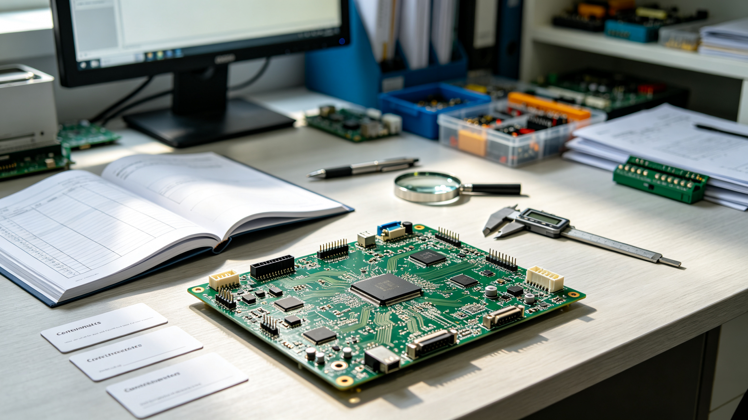
If you're new to PCB design or manufacturing, the number of acronyms and technical terms can be overwhelming. From Gerber to AOI, from FR-4 to HDI — each term represents a concept that you'll encounter at some point in your hardware development journey.
This glossary covers the most common PCB and PCBA terms, organized by category, to help you navigate design reviews, manufacturer conversations, and datasheets with confidence.
Trace
A copper pathway on a PCB that carries electrical signals between components. Trace width is critical — wider traces carry more current, while narrower traces support higher signal density. For high-speed designs, trace geometry must be controlled for impedance matching.
Via
A plated hole that connects traces from one layer of a PCB to another. Common types include:
Through-hole via: Goes all the way through the board
Blind via: Connects an outer layer to an inner layer
Buried via: Connects two or more inner layers without reaching the surface
Plane
A continuous area of copper on a PCB layer, typically used for power distribution or grounding. Planes provide low-impedance return paths and help with heat dissipation.
Thermal Relief
Small traces that connect a pad to a copper plane. These act as heat "spokes" to make soldering easier — without them, the large copper plane would act as a heatsink and prevent proper soldering.
Fiducial Marker
A target registration mark used by pick-and-place machines for alignment during assembly. Fiducials help machines accurately position components on the board.
Silkscreen
The layer of text and symbols printed on the PCB surface. It shows component designators, polarity markers, and other information needed for assembly and troubleshooting.
IPC Standards
Industry standards for PCB design, fabrication, and assembly maintained by IPC. Key standards include:
IPC-A-600: Acceptability of printed boards
IPC-A-610: Acceptability of electronic assemblies
IPC-6012: Performance specification for rigid PCBs
IPC-2221: Generic standard for printed board design
Panelization
The process of arranging multiple PCB designs onto a single manufacturing panel to improve production efficiency. Individual boards are separated using V-scoring, tab routing, or mouse bites.
Mouse Bites
Small perforations or drilled holes along the edge of a PCB that allow it to be easily snapped off from a panel after assembly.
Gerber Files
The standard file format used to describe PCB layers to manufacturers. Gerber files (RS-274X) are generated from your EDA tool and define copper layers, solder mask, silkscreen, and paste layers.
NC Drill File (Excellon)
A separate file that defines hole locations, sizes, and types for drilling. This file works alongside Gerber files to specify where holes should be drilled.
DFM (Design for Manufacturing)
The practice of designing PCBs with manufacturing constraints in mind. A good DFM review catches issues like insufficient trace spacing, inadequate annular ring, or high aspect ratio holes before production begins.
DRC (Design Rule Check)
An automated check performed by EDA software to verify that a design meets spacing, size, and other physical constraints. DRC is a key step before generating Gerber files.
Prepreg
A dielectric material used to bond PCB layers together during lamination. Prepreg is fiberglass fabric pre-impregnated with partially cured resin that melts and cures under heat and pressure.
Lamination
The process of bonding multiple PCB layers together using heat and pressure. The resin in prepreg melts, flows, and then cures to create a solid board.
Annular Ring
The copper pad ring that surrounds a drilled hole in a PCB. A sufficient annular ring is essential for reliable plated through-hole connections.
Copper Weight
The thickness of copper on a PCB layer, measured in ounces per square foot. Common weights include 1oz (35µm) and 2oz (70µm).
HDI (High-Density Interconnect)
PCBs with finer lines, smaller vias, and higher connection density than standard boards. HDI typically uses microvias (laser-drilled holes under 0.15mm) and sequential lamination.
Blind/Buried Via
Vias that don't go all the way through the board. Blind vias connect an outer layer to an inner layer; buried vias connect inner layers to each other.
Castellated Holes
Plated half-holes along the edge of a PCB, commonly used for module-to-motherboard soldering.
SMT (Surface Mount Technology)
The dominant method for assembling PCBs. Components are placed directly onto pads on the board surface and soldered using reflow ovens.
Pick-and-Place
The automated process of placing SMT components onto a PCB before soldering. Machines use fiducial markers for alignment.
Reflow Soldering
The process of soldering SMT components by applying solder paste, placing components, and heating the entire board in a reflow oven to melt the solder.
Wave Soldering
A soldering process primarily used for through-hole components, where the board passes over a wave of molten solder.
AOI (Automated Optical Inspection)
A machine-based visual inspection method that checks PCBs for defects after assembly. AOI can catch missing components, misalignment, solder bridges, and incorrect part markings.
X-Ray Inspection (AXI)
X-ray imaging used to inspect hidden solder joints — especially BGAs, QFNs, and other components where the solder joints are not visible from the outside.
ICT (In-Circuit Test)
An electrical test that uses a bed-of-nails fixture to contact test points on an assembled board. ICT checks component values, shorts, opens, and power supply voltages.
Flying Probe Test
A bare-board test method where motor-driven probes move across the board to check for opens and shorts. No custom fixture is required, making it ideal for prototypes and small batches.
FCT (Functional Test)
The final test that powers up the board and verifies it operates correctly in its intended application. This is the only test that confirms the board actually works.
SPI (Solder Paste Inspection)
A machine that checks solder paste deposits before components are placed. Since roughly 60% of SMT defects come from the printing process, SPI is essential for quality control.
FR-4
The most common PCB substrate material — a glass-reinforced epoxy laminate. FR-4 is used for standard rigid boards and meets UL94 V-0 flammability requirements.
Prepreg
Partially cured resin used between layers during lamination. Prepreg melts and bonds layers together under heat and pressure.
Copper Foil
The conductive layer on a PCB. Copper thickness is specified by weight — 1oz, 2oz, 3oz, etc. Heavy copper (3oz+) is used for power applications.
Surface Finishes
Protective coatings applied to exposed copper pads to prevent oxidation and ensure solderability. Common finishes include:
| Finish | Best For | Planarity | Cost |
|---|---|---|---|
| ENIG | BGA, fine-pitch | Excellent | Medium |
| OSP | Cost-sensitive SMT | Excellent | Low |
| HASL | General through-hole | Poor | Low |
| Immersion Silver | High-frequency | Excellent | Medium |
| ENEPIG | Wire bonding, mixed assembly | Excellent | High |
| Acronym | Full Term | Category |
|---|---|---|
| PCB | Printed Circuit Board | General |
| PCBA | PCB Assembly | General |
| SMT | Surface Mount Technology | Assembly |
| AOI | Automated Optical Inspection | Test |
| ICT | In-Circuit Test | Test |
| FCT | Functional Test | Test |
| HDI | High-Density Interconnect | Design |
| DFM | Design for Manufacturing | Process |
| DRC | Design Rule Check | Process |
| SPI | Solder Paste Inspection | Assembly |
| BGA | Ball Grid Array | Component |
| FR-4 | Flame Retardant 4 | Material |
| ENIG | Electroless Nickel Immersion Gold | Finish |
???? www.anypcba.com/contact-us/
???? We help hardware engineers bridge the gap between design and manufacturing — from DFM review to full turnkey PCBA. Have a project in mind? Send us your files. We'll provide a DFM review and a transparent quote.




