Choosing the Right PCB Board Type: A Comprehensive Guide
Printed circuit boards (PCBs) are the foundation of modern electronics, acting as the nervous system of devices that permeate our daily lives, from smartphones to advanced medical equipment. Selecting the correct PCB board type is crucial for ensuring the performance, reliability, and cost-effectiveness of any electronic device. This article demystifies the common PCB board types and their uses, providing practical insights into choosing the right board for your next project.
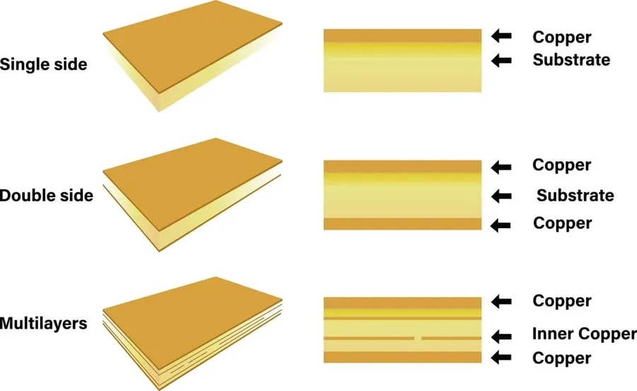
Single-Sided PCBs: The Simplest Form
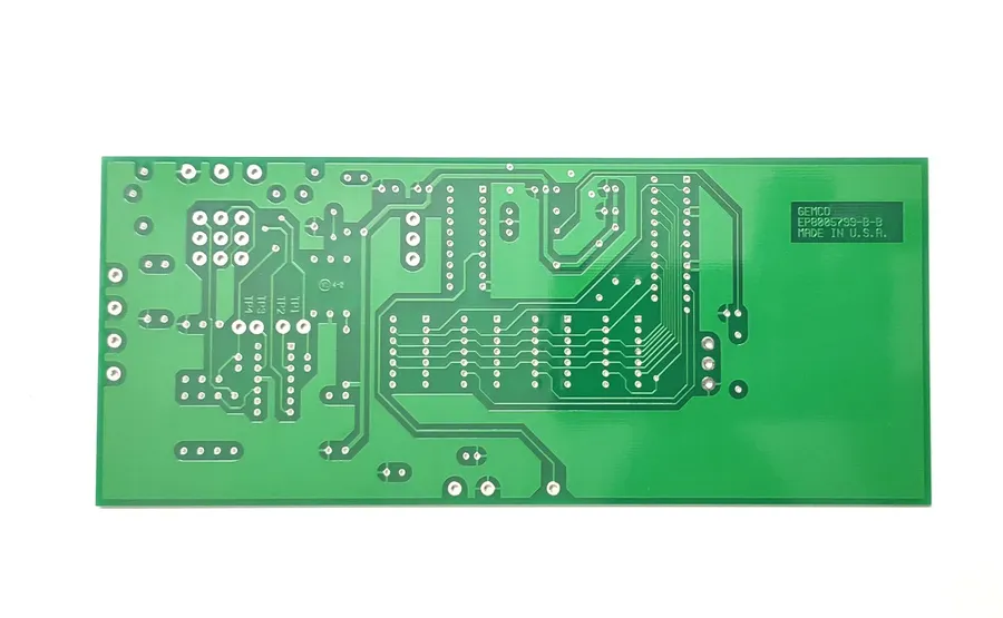
Single-sided PCBs represent the foundational level of printed circuit board technology, characterized by a conductive layer, typically copper, on only one side of the substrate. This design simplicity makes them well-suited for less complex electronic devices, where component density and performance demands are moderate. Their straightforward structure and ease of manufacture contribute to their cost-effectiveness.
- Construction:
Single-sided PCBs feature a single layer of conductive material on one side of an insulating substrate, with components mounted on the same side as the copper traces. This limits the density and complexity of circuits that can be accommodated. - Advantages:
Their primary advantages include low manufacturing costs, simplified design process, and suitability for high-volume production of basic electronic devices. These advantages make them a cost-effective solution for simple electronic projects. - Disadvantages:
However, they have several disadvantages. Single-sided PCBs lack routing flexibility due to only one conductive layer, limiting the complexity of the circuit and making them unsuitable for sophisticated applications. This limits the circuit density, making complex signal paths difficult to implement. - Typical Applications:
They are frequently used in simple electronics, such as basic power supplies, single-function LED lighting, and low-end consumer electronics where circuit density and performance requirements are minimal, such as in simple toys, calculators and basic appliance controls. - Limitations:
Single-sided PCBs are unsuitable for applications requiring high density circuits, multiple signal layers, and complex signal routing. They are also vulnerable to external interferences due to the simplicity of their design. For these scenarios, double sided or multilayer PCBs are the better option.
Double-Sided PCBs: Expanding Capabilities
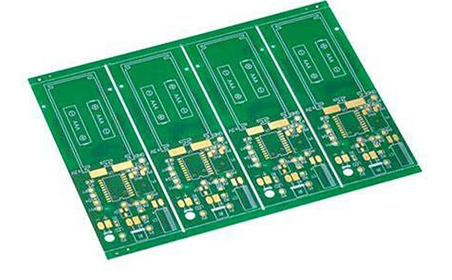
Double-sided PCBs represent a significant step up in complexity and functionality compared to their single-sided counterparts. By featuring a conductive layer on both the top and bottom surfaces of the board, they enable the creation of more intricate circuits and offer greater flexibility in component placement and routing. This design effectively doubles the available area for electrical connections, making them suitable for a broader range of applications.
| Feature | Single-Sided PCBs | Double-Sided PCBs |
|---|---|---|
| Conductive Layers | One | Two |
| Circuit Complexity | Lower | Higher |
| Component Density | Lower | Higher |
| Interconnection Flexibility | Limited | Increased |
| Cost | Lower | Moderate |
| Typical Applications | Simple Electronics | Consumer Electronics, Industrial Controls |
The increased circuit density and interconnection options of double-sided PCBs translate to several advantages. They allow for more complex circuit designs to be realized in the same physical space, and enable more efficient use of board real estate. The presence of conductive layers on both sides enables more intricate routing, utilizing vias to connect pathways on the opposite faces. This results in a more compact solution with greater functionality compared to single-sided boards. While slightly more complex and costly to produce than single-sided PCBs, the improved electrical performance and component integration offered by double-sided boards make them a more suitable solution for many applications.
Multilayer PCBs: High-Density and Complex Designs
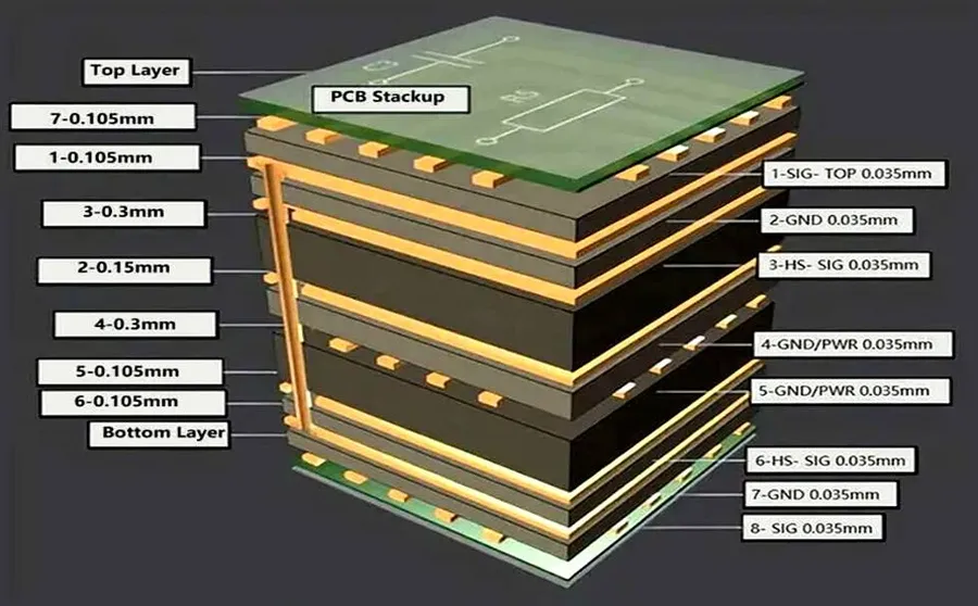
Multilayer PCBs are characterized by their construction of three or more conductive layers, separated by insulating material. This allows for highly complex circuit designs within a compact footprint, crucial for modern high-performance electronics.
The ability to pack more circuitry into a smaller space makes them ideal for applications where size and density are critical constraints.
| Feature | Single-Sided PCB | Double-Sided PCB | Multilayer PCB |
|---|---|---|---|
| Number of Conductive Layers | 1 | 2 | 3 or more |
| Circuit Complexity | Low | Medium | High |
| Density | Low | Medium | High |
| Cost | Lowest | Moderate | Higher |
| Typical Applications | Simple Electronics | Intermediate Electronics | Advanced Electronics |
The layers of a multilayer PCB are typically interconnected via vias, small plated-through holes that allow signals to pass from one layer to another. This intricate connectivity is essential for routing complex signals and power distribution across the board.
Applications for multilayer PCBs include:
- High-performance computing
Servers, workstations, and high-end graphic cards that require complex signal routing and power distribution. - Telecommunications
Network routers, switches, and base stations that demand high-speed signal processing and data transmission. - Medical equipment
Sophisticated medical imaging and diagnostic devices, where reliability and compactness are essential. - Aerospace and defense
Navigation systems, radar systems, and control systems that require extreme performance and high reliability. - Consumer electronics
Advanced smartphones, tablets, and gaming consoles that demand high functionality within a small physical space.
Rigid PCBs: Robust and Stable
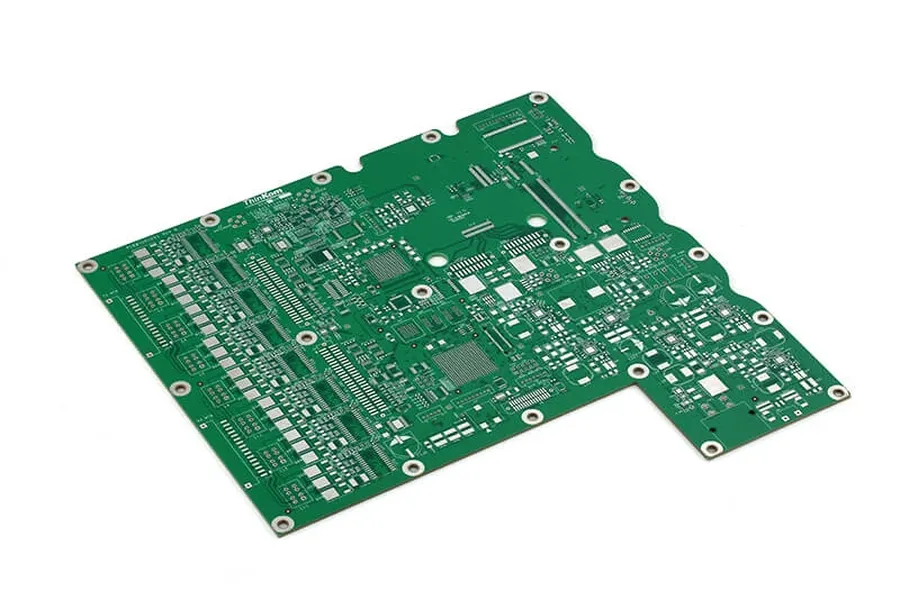
Rigid PCBs, characterized by their solid and inflexible substrate, represent the most ubiquitous type of printed circuit board. Their inherent stability and durability make them a cornerstone in a vast array of electronic applications, ranging from simple consumer electronics to complex industrial equipment.
- Key Characteristics
Rigid PCBs are constructed on a solid substrate like FR-4, which offers mechanical strength and electrical insulation. - Structural Integrity
They maintain their shape and structure, ensuring reliable connections and performance even under stress. This makes them suitable for components that need to remain stable in their working environment. - Cost-Effective
Rigid PCBs are usually more cost-effective compared to flexible or rigid-flex PCBs, particularly in mass production scenarios.
| Feature | Description |
|---|---|
| Material | Typically FR-4, but can include other materials like CEM-1, CEM-3 |
| Flexibility | Inflexible, maintains a defined shape |
| Durability | Highly robust and resistant to physical stress |
| Cost | Generally more cost-effective than flex or rigid-flex PCBs |
| Applications | Consumer electronics, industrial equipment, computing devices, and automotive electronics |
Flex PCBs: Flexibility for Unique Applications
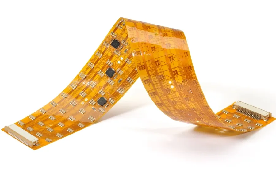
Flexible PCBs (Flex PCBs) utilize bendable materials, enabling them to conform to various shapes and fit within constrained spaces, making them ideally suited for intricate designs and dynamic environments where traditional rigid boards would fail. This inherent flexibility provides significant advantages in applications requiring compact and adaptable electronic solutions.
- Material Composition
Flex PCBs are typically constructed using polyimide or polyester films, known for their excellent dielectric properties and ability to withstand bending and flexing without fracturing. - Dynamic Applications
Flex PCBs are crucial for applications requiring repeated bending or flexing, such as in foldable devices, wearable electronics, and automotive sensor systems. - Space Saving
Their ability to bend and fold allows for dense packaging, resulting in smaller and lighter devices with complex circuitry. - Improved Reliability
By eliminating the need for connectors and cables in some applications, flexible PCBs can increase overall reliability due to fewer points of failure.
| Feature | Flex PCB | Rigid PCB |
|---|---|---|
| Flexibility | High | None |
| Material | Polyimide/Polyester | FR-4/Composite |
| Applications | Wearables, Foldables, Medical | Computers, Appliances, Industrial |
| Space Constraints | Excellent Adaptability | Limited |
Rigid-Flex PCBs: Combining Flexibility and Rigidity
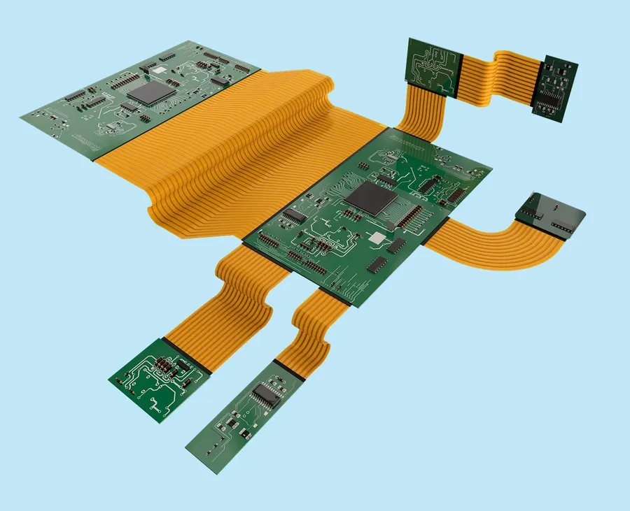
Rigid-flex PCBs represent a sophisticated approach to circuit board design, seamlessly integrating the advantages of both rigid and flexible substrates within a single circuit board. This hybrid construction provides unique mechanical and electrical benefits, enabling complex three-dimensional designs and enhanced durability in dynamic applications.
Rigid-flex PCBs are not merely two separate boards joined together; rather, they are manufactured as a single integrated unit where rigid sections, usually made of FR-4, are interconnected by flexible polyimide regions. This seamless integration avoids connectors and cabling, thereby reducing potential points of failure, saving space, and improving overall system reliability.
| Feature | Rigid PCB | Flex PCB | Rigid-Flex PCB |
|---|---|---|---|
| Flexibility | No | Yes | Hybrid |
| Complexity | Low to Medium | Medium | High |
| Durability | High | Medium | High |
| Applications | General purpose | Dynamic, flexible | Complex, multi-functional |
| Cost | Low | Medium to High | High |
The key advantage of rigid-flex PCBs lies in their ability to conform to the intricate shapes and packaging constraints prevalent in modern electronics. The rigid portions of the board support component mounting and robust interconnections, while the flexible sections allow for bending and twisting, facilitating connections between different parts of an assembly, which is often impossible with conventional boards.
Rigid-flex PCBs find their application in a wide array of industries where space and reliability are paramount. These include aerospace systems, medical devices, automotive electronics, and high-end consumer electronics such as digital cameras and wearables. In each of these scenarios, the ability to reduce overall product size, increase reliability, and accommodate dynamic movements makes rigid-flex PCBs the preferred solution.
The design and manufacturing of rigid-flex PCBs require specialized knowledge and precise techniques. Consideration must be given to materials selection, layer stack-up, and the appropriate integration of rigid and flexible sections to ensure both electrical and mechanical integrity. Although initial costs may be higher, the long-term benefits of reduced assembly time, increased durability, and improved reliability often outweigh the extra investment.
Frequently Asked Questions About PCB Board Types
This section addresses common questions regarding PCB board types, offering clear and concise answers to enhance understanding of their classifications, materials, and applications.
- What are the primary classifications of PCB boards?
PCBs are primarily classified based on the number of conductive layers: single-sided, double-sided, and multilayer. Single-sided PCBs have conductive material on one side, double-sided on both, and multilayer PCBs incorporate three or more layers for complex circuits. This layering determines the board's capacity for signal routing and complexity. The structure directly impacts the application. - What are the main differences between rigid, flexible, and rigid-flex PCBs?
Rigid PCBs are built on a solid, inflexible substrate, offering stability and durability, ideal for general electronic devices. Flexible PCBs use flexible materials that can bend and conform to different shapes, suitable for dynamic applications. Rigid-flex PCBs combine both rigid and flexible areas on the same board, offering versatility for complex designs and applications where both stability and flexibility are needed. Each of these board types serve different design needs and performance requirements. - What is a Type 4 PCB?
The term 'Type 4 PCB' does not conform to a standard classification in the industry. However, it could be referring to a specific type of multilayer PCB with unique characteristics, potentially relating to a specific industry standard, or material composition. Without further context, its exact properties can not be clearly defined, requiring more information about the specific manufacturing process, standard or industry in question. It is best practice to refer to classifications defined by IPC standards. - What is a Type 3 PCB?
Similar to 'Type 4 PCB', 'Type 3 PCB' is not a universally recognized classification in the PCB manufacturing standards. If used, it likely references a specific type of multilayer PCB with unique characteristics, maybe within a specific manufacturer or industry. It can often depend on specific internal standards or a particular industry need. Clear communication about design requirements is essential for a successful PCB production. Without further context, it is impossible to provide a definitive answer. - What materials are commonly used to construct PCBs, and how do their properties differ?
Common PCB materials include FR-4 (fiberglass reinforced epoxy), which is a cost-effective and widely used material that provides good electrical insulation and flame resistance. Polyimide offers high temperature resistance and flexibility, suitable for demanding environments, while Teflon (PTFE) has superior electrical properties and is ideal for high frequency applications. Each of these materials' distinct properties have significant impacts on thermal management and the electrical performance of the circuit board. - What considerations are important when selecting a PCB board type for a project?
Selecting the right PCB board type requires consideration of the application's electrical performance requirements, operating environment, mechanical requirements, manufacturing cost, production volume, and longevity. Single-sided PCBs are suitable for basic low cost projects, while multilayer PCBs are required for high density, complex systems. The decision must align with the design's needs for functionality, durability, and cost effectiveness. - What are the 7 types of PCB testing methods?
There are various PCB testing methods to ensure reliability and functionality. These include: Visual inspection to detect physical defects, In-circuit testing (ICT) to verify component placement and electrical connections, Flying probe testing for electrical verification without a test fixture, Automated optical inspection (AOI) to identify defects automatically, X-ray inspection for internal solder joints, Functional testing to evaluate operation, and Environmental testing to determine performance under varying conditions. Thorough testing is essential to ensuring a product's reliability and performance.
PCB Material Considerations
The performance and reliability of a PCB are significantly influenced by the materials used in its construction. Selecting the appropriate material is critical for meeting the electrical, mechanical, thermal, and environmental requirements of the application. This section delves into the key materials used in PCB manufacturing, highlighting their properties and suitability for different applications.
| Material | Description | Advantages | Disadvantages | Typical Applications |
|---|---|---|---|---|
| FR-4 | A composite material made from woven fiberglass cloth with an epoxy resin binder. | Good mechanical strength, cost-effective, widely available, good electrical insulation properties. | Limited thermal performance compared to other materials, moderate electrical performance at high frequencies. | General-purpose PCBs, consumer electronics, low to mid-frequency applications. |
| Polyimide | A high-performance polymer known for its exceptional thermal and chemical resistance. | Excellent thermal stability, high temperature performance, good chemical resistance, superior electrical properties at high frequencies. | Higher cost compared to FR-4, may require specialized processing. | Aerospace, high-reliability applications, high-temperature environments, flexible PCBs. |
| Teflon (PTFE) | A fluoropolymer with exceptional electrical and dielectric properties. | Very low dielectric loss, excellent for high frequency applications, high chemical resistance, low moisture absorption. | Expensive, challenging to process, less mechanically stable. | Microwave and RF applications, high-speed digital circuits, aerospace, radar systems. |
| Aluminum | A metal substrate with high thermal conductivity and mechanical strength. | Excellent heat dissipation, good mechanical robustness, lightweight. | Electrically conductive, requires additional insulation layers, not suitable for all PCB types. | LED lighting, power electronics, high-power applications. |
| Ceramic | An inorganic material with superior thermal conductivity, electrical properties and chemical inertness. | Excellent thermal conductivity, good electrical insulation properties, high temperature resistance, stable. | High cost, brittle, difficult to machine. | High-frequency applications, power modules, aerospace applications, medical devices. |
Selecting the Right PCB Board Type for Your Project
Choosing the appropriate PCB board type is a critical decision in any electronic project, directly influencing the final product's performance, cost, and reliability. This selection process requires careful evaluation of project-specific requirements, balancing functionality with practical considerations.
The following factors should be carefully considered when selecting a PCB board type:
- Application Requirements
The intended application dictates the necessary complexity and performance. Simple circuits may suffice with single- or double-sided PCBs, while high-performance devices often demand multilayer or rigid-flex PCBs. - Circuit Complexity
Complex circuits with numerous components and interconnections require more layers for routing and signal integrity. Multilayer PCBs are ideal for these applications. - Cost Constraints
The cost of PCBs increases with the number of layers and the complexity of the design. Single-sided boards are the most economical, while rigid-flex PCBs tend to be the most expensive. The PCB material also plays a key role in the overall cost. - Environmental Factors
The operating environment can influence material selection and board type. Temperature fluctuations, humidity, or mechanical stress necessitate specific materials (e.g., high-Tg FR-4, Polyimide) and flexible PCB options. - Physical Space Limitations
Size constraints may drive the need for multilayer or flexible PCBs, especially in miniaturized devices. Using high-density interconnect (HDI) technologies can further optimize the use of space. - Performance Requirements
High-speed and high-frequency applications require PCB materials with low dielectric loss and controlled impedance. Multilayer PCBs with specific stack-ups are essential to mitigate signal integrity issues. - Production Volume
The production volume impacts the decision, For high volume, choose a lower-cost and readily available PCB. For low volume prototypes, a more expensive PCB with unique capabilities may be justified.
| PCB Type | Complexity | Cost | Application | Advantages | Disadvantages |
|---|---|---|---|---|---|
| Single-Sided | Low | Lowest | Simple circuits, basic electronics | Simple design, low cost | Limited routing, low density |
| Double-Sided | Medium | Low to Medium | Intermediate electronics, prototyping | Increased routing options, moderate density | Limited layer count, potential for signal crossing issues |
| Multilayer | High | Medium to High | Complex circuits, high-performance electronics | High density, complex routing, enhanced signal integrity | Higher cost, more complex manufacturing |
| Rigid | Variable | Low to Medium | Most common, general-purpose electronics | Robust, Stable, widely available | Inflexible, limited to flat shapes |
| Flex | Variable | Medium to High | Dynamic environments, specific shapes, space constraint applications | Flexible, adapts to different shapes | Higher cost, more complex manufacturing |
| Rigid-Flex | High | High | Complex electronic systems with flexible and rigid requirements | Combines rigidity and flexibility, versatile | Highest cost, complex manufacturing |
Future Trends in PCB Board Technology
The landscape of PCB technology is continually evolving, driven by the demand for smaller, faster, and more efficient electronics. Key trends include the development of advanced materials, higher-density interconnect (HDI) technologies, and the integration of new functionalities to meet emerging application needs.
- Advanced Materials
Research into new substrate materials beyond traditional FR-4 is ongoing. These include materials with superior thermal properties, higher dielectric constants, and improved mechanical strength. Examples include ceramics, liquid crystal polymers (LCP), and novel resin systems. The goal is to enable higher operating temperatures, reduced signal loss, and better performance in demanding environments. - High-Density Interconnect (HDI)
HDI technology focuses on miniaturizing PCB features, such as vias, traces, and component pads. This allows for increased component density and improved signal integrity. Techniques like microvias, laser direct imaging, and fine-line etching are key enablers for HDI PCBs. This trend supports the reduction in size and weight for portable and wearable electronics. - Embedded Components
Embedding passive and active components directly within the PCB layers offers significant advantages in terms of space-saving and performance improvements. This allows for more compact designs by placing components internal to PCB layers or within internal spaces or cavities within the PCB layers. Embedded capacitors, resistors, and even integrated circuits are being explored. It results in lower parasitic inductance and capacitance, leading to improved electrical performance. - Additive Manufacturing (3D Printing)
3D printing of PCBs is a rapidly growing trend. It offers the potential for faster prototyping, more complex geometries, and on-demand production. Direct write technologies for conductive inks and polymers enable the creation of custom PCBs without the need for traditional manufacturing processes. This is particularly useful for customized, small-batch, and complex PCB manufacturing. - Flexible and Stretchable Electronics
The development of flexible and stretchable PCBs is enabling new applications, such as wearable sensors, biomedical devices, and conformable displays. New materials, such as conductive polymers, elastomers, and thin-film metallization, are driving progress. These technologies cater to unique form factors and dynamic conditions. They provide opportunities in implantable medical devices and flexible display systems. - Sustainable PCB Manufacturing
Environmental concerns are driving the development of more sustainable PCB manufacturing processes. This includes exploring bio-based materials, reducing the use of hazardous chemicals, and improving waste management practices. This trend is aimed at aligning with growing environmental regulations. It emphasizes the circular economy and reduces the environmental impact of electronics production. - Integration of Advanced Functionalities
Beyond traditional circuitry, PCBs are becoming platforms for integrated functionalities. This includes integrating sensors, wireless communication modules, and power management circuits directly onto the PCB. This trend is driven by the need for more compact and interconnected devices. It facilitates the design of sophisticated electronic systems with enhanced capabilities.
Choosing the correct PCB board type is pivotal to the success of any electronic design project. Understanding the differences between single-sided, double-sided, multilayer, rigid, flex, and rigid-flex PCBs allows you to make informed decisions based on your specific application needs and budget. As technology advances, so will PCB designs, paving the way for more powerful and innovative electronics.