Choosing the Right Proto PCB Boards: A Comprehensive Guide
In the fast-paced world of electronics, rapid prototyping is key. Proto PCB boards, the unsung heroes of innovation, are essential for quickly testing and refining electronic designs. This article will delve into the different types of proto PCB boards, their uses, and how to make the right choice for your project, with a focus on maximizing the utility of proto pcb boards in the development cycle.
Understanding Proto PCB Boards: Definition and Purpose
Proto PCB boards, often referred to as prototype printed circuit boards, are fundamental tools in electronics development, serving as a crucial bridge between theoretical circuit designs and final product realization. These boards are specifically designed to facilitate the rapid construction and testing of electronic circuits, enabling engineers and hobbyists to validate their designs before committing to mass production. The adaptability and flexibility of proto PCBs are paramount, allowing for iterative design improvements and modifications, significantly reducing both time and cost associated with product development. These boards play a vital role in identifying design flaws early, ensuring that the final product meets performance and reliability standards. Their utilization provides a tangible platform to test the schematic and to fine-tune the electrical characteristics of a circuit.
Types of Proto PCB Boards: Breadboards vs. Perfboards vs. Custom PCBs
Proto PCB boards serve as a crucial stepping stone in electronics development, allowing engineers and hobbyists to test and refine circuits before committing to a final design. These boards come in various forms, each offering unique advantages and disadvantages based on project requirements, complexity, and cost considerations. The three most common types are breadboards, perfboards, and custom proto PCBs.
| Feature | Breadboard | Perfboard | Custom Proto PCB |
|---|---|---|---|
| Connectivity | Solderless, reusable connections | Requires soldering for permanent connections | Soldered or surface-mounted components |
| Durability | Low, not suitable for permanent circuits | Moderate, semi-permanent | High, designed for robust and reliable operation |
| Complexity | Best for simple, low-frequency circuits | Suitable for moderately complex circuits | Handles complex, high-density, and high-frequency circuits with fine pitch components |
| Cost | Low | Moderate | Higher initial cost but suitable for multiple prototype runs, and also depends on complexity |
| Ease of Use | Very easy for rapid prototyping and debugging | Moderate, requires soldering skills | Requires design software knowledge and fabrication expertise |
| Flexibility | Highly flexible for component and configuration changes | Moderate flexibility with some modifications possible | Less flexible, requires board modification for design changes |
| Frequency Handling | Limited to low frequencies, susceptible to signal interference | Better than breadboards, but has limitations in higher frequencies | Designed for specific frequency requirements |
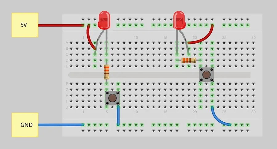
Breadboards are ideal for initial prototyping, especially for beginners, they facilitate quick component placement and easy modifications without soldering. However, their temporary nature and limitations with high frequencies make them unsuitable for more demanding projects. Perfboards offer a step up in terms of durability, allowing for more permanent circuit construction through soldering. They're suitable for semi-permanent solutions but can be time-consuming for complex layouts. Custom proto PCBs, while requiring more upfront effort in design and fabrication, provide the most tailored and robust solution. They can handle complex layouts and high-frequency circuits, making them perfect for designs nearing production.
Key Factors to Consider When Choosing Proto PCB Boards
Selecting the appropriate proto PCB board is crucial for successful electronics prototyping. This decision hinges on several key factors, including the complexity of the project, the physical size of the required circuit, the necessary durability for testing, and budgetary limitations. Ease of use also plays a significant role in ensuring the prototyping process is efficient and effective.
| Factor | Description | Impact on Proto PCB Choice |
|---|---|---|
| Project Complexity | The intricacy of the circuit design, including the number of components and layers. | More complex projects may necessitate larger proto boards, multilayer PCBs, or even custom designs. Simpler projects can utilize basic perfboards or breadboards. |
| Circuit Size | The physical dimensions of the circuit being prototyped. | Larger circuits require larger proto boards with sufficient space for component placement and routing, while smaller circuits can be tested on more compact boards. |
| Durability Needs | The extent to which the prototype will be handled, tested, and reused. | Projects needing extensive or rugged testing require durable materials and construction methods. Fragile prototypes may be suitable for breadboards, while more robust prototypes could benefit from custom PCBs or more solid perfboards. |
| Cost Considerations | Budget allocated for prototyping | Simple breadboards are low cost, but less robust, while custom PCBs provide excellent robustness and functionality, but are expensive and time-consuming. Balancing cost and project requirements is critical. |
| Ease of Use | How straightforward it is to design and assemble the circuits on the selected board. | Ease of use can be related to factors such as the clarity of markings, simplicity of hole placement (for perfboard), or availability of specific mounting locations. This should be in consideration for the users experience. |
Proto PCB Board Materials and Construction
The performance, durability, and longevity of proto PCB boards are significantly influenced by the materials used in their construction and the methods employed in their fabrication. Understanding these aspects is crucial for selecting the appropriate board for specific prototyping needs. This section explores the common materials and construction methods of proto PCB boards.
| Material | Description | Pros | Cons | Typical Use |
|---|---|---|---|---|
| FR4 | A composite material made of woven fiberglass cloth with an epoxy resin binder. | Excellent mechanical strength, good electrical insulation, widely available, cost-effective. | Can be difficult to machine, can absorb moisture if not properly sealed, not very flexible. | Most general-purpose proto boards and final PCBs. |
| Phenolic | A paper-based material impregnated with phenolic resin. | Low cost, easier to machine than FR4. | Less durable than FR4, poorer electrical performance and prone to moisture absorption. | Simple, low-cost projects where durability and signal integrity are not critical. |
| Aluminum | A metal substrate with a dielectric layer. | Excellent thermal conductivity, robust and durable. | More expensive, requires specific fabrication techniques, can be harder to work with for prototyping. | High-power applications, LED lighting, and where heat dissipation is crucial. |
| CEM-1 | Composite material with paper and woven glass fabric with epoxy. | Better electrical and mechanical performance than phenolic. More robust than phenolic. | More expensive than phenolic, less durable than FR4. | Cost-sensitive projects that require better performance than phenolic boards. |
Proto PCB boards are typically constructed using one of the following methods, impacting their complexity and signal handling capabilities:
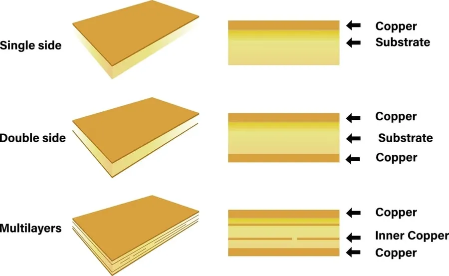
- Single-Sided
The simplest type, with conductive traces on only one side of the board. Suitable for basic circuits with few components. Less costly to manufacture. - Double-Sided
Has conductive traces on both sides, allowing for more complex circuits and increased component density. Typically utilizes plated through-holes for electrical connections between both sides. - Multilayer
Consists of multiple layers of conductive traces sandwiched together by dielectric layers. Supports very complex circuits with many components and requires specialized manufacturing techniques. These boards can have 4, 6, 8 or even more layers, allowing for high density designs.
Designing and Assembling Circuits on Proto PCB Boards
Efficiently designing and assembling circuits on proto PCB boards is crucial for successful prototyping. This process involves careful component placement, strategic wiring, and systematic troubleshooting to ensure the prototype functions as intended. Effective utilization of proto PCB boards can significantly streamline the development process.
- Component Placement
Plan the physical arrangement of components based on your schematic. Consider signal flow, power distribution, and physical constraints. Place components logically to minimize wire lengths and potential interference. Group related components closely to minimize signal path lengths. Avoid placing heat-sensitive components near heat-generating ones. Ensure adequate spacing for soldering. - Wiring Techniques
Use point-to-point wiring (using wire-wrapping or soldering). Keep wires as short and direct as possible. Use different colors to differentiate power, ground, and signal wires. Ensure secure and reliable connections to prevent shorts and opens. Route power and ground traces separately when designing custom PCBs, as it ensures low-impedance paths and reduces noise. - Power Supply Considerations
Design a reliable power distribution network. Use decoupling capacitors near power pins of integrated circuits to reduce noise. Ensure power and ground connections are robust enough to handle the current draw. If multiple voltage levels are required, plan carefully how to supply them. Check datasheets for power requirements and recommendations. - Effective Use of Proto PCB Boards
Use standard proto board layouts as a base for component placement. Follow the board's grid system and component footprints to guide your assembly. Clearly mark all components and wires for easy identification and debugging. Consider using DIP sockets for integrated circuits, which simplifies replacement. - Troubleshooting
Verify your circuit with a multimeter to ensure continuity and proper voltages. Start by checking basic functionality first, gradually moving to more complex circuits. Isolate potential sources of errors by testing components and circuit subsections individually. Use a logic analyzer or oscilloscope, if needed, to trace signals and diagnose timing and other signal integrity issues. Use your schematic as the primary reference when troubleshooting. - Documentation
Keep track of all modifications and changes you make to the prototype, including a revised schematic and layout of your modifications. Document every step carefully. This is important for effective troubleshooting and re-creation if needed. Thorough documentation will be very useful when transitioning to a final PCB design.
Where to Buy Proto PCB Boards: Comparison of Suppliers
Selecting the right supplier for proto PCB boards is crucial for ensuring quality, cost-effectiveness, and timely delivery of your prototypes. This section compares different types of suppliers, including online marketplaces, specialized manufacturers, and local electronics stores, to help you make an informed decision based on your project needs.
| Supplier Type | Examples | Pros | Cons | Best Use Cases |
|---|---|---|---|---|
| Online Marketplaces | Amazon, eBay | Wide variety of options, generally lower prices, convenient purchasing | Variable quality, potential for counterfeit products, less control over specifications | Simple projects with less critical specifications or for beginners seeking low cost options |
| Specialized PCB Manufacturers | PCBWay, JLCPCB, Seeed Studio | High-quality boards, custom specifications, design for manufacturing (DFM) checks, production scalability | Higher cost than marketplaces, longer lead times, potentially more complex ordering process | Complex or high-performance prototypes that require precise specifications and high reliability and also for larger production needs |
| Local Electronics Stores | Fry's Electronics (if available), Micro Center | Immediate availability, ability to inspect boards before purchase, good for quick prototyping. | Limited selection, generally higher prices, lack of customization options. | Simple prototypes when you need a proto board immediately and do not require special customizations. |
Frequently Asked Questions about Proto PCB Boards
This section addresses common inquiries about proto PCB boards, providing clarity on their functionality, applications, costs, and differences from related prototyping tools. Understanding these points is crucial for effectively utilizing proto PCBs in electronics design.
- What exactly is a prototype PCB?
A prototype PCB, or proto PCB, is a circuit board specifically designed for testing and validating electronic circuit designs before mass production. It allows engineers and hobbyists to build and evaluate their circuits on a physical board, verifying their design, component placement and wiring. - What are the primary uses for proto PCB boards?
Proto PCBs are used to create working models of electronic circuits. This includes validating circuit functionality, testing different component configurations, checking signal integrity, and evaluating the overall design. It is a crucial step for risk mitigation and design optimization. - How much does a PCB prototype typically cost?
The cost of a PCB prototype varies widely depending on factors such as board size, number of layers, material selection (e.g., FR4 vs. specialized substrate), and the quantity of prototypes ordered. Simple, single-layer designs can be quite inexpensive, while complex, multi-layer boards or prototypes with unique material requirements will cost significantly more. Prices can range from tens to hundreds of dollars depending on specifications and supplier. - Is a protoboard the same as a breadboard?
No, a protoboard (also known as a perfboard) and a breadboard are not the same. A breadboard is used for temporary circuit construction and is reusable without soldering. A protoboard is a more permanent solution; components are typically soldered onto a perfboard. While a breadboard is suitable for quick testing, a protoboard is for more robust and durable proto circuits. - Can I use proto PCB boards for final product production?
While proto PCBs can be useful for initial low-volume production runs, they are not intended for large-scale manufacturing due to constraints related to manufacturing tolerance and standardization. Proto PCB are primarily for testing and verification, and should be followed by custom designed boards optimized for production and scalability. - What are some common materials used in proto PCB construction?
Common materials include FR4 (a glass-reinforced epoxy laminate), which is cost-effective and widely used, and phenolic paper, used for simpler boards. Other more specialized materials may be used for higher-performance needs. Material choice influences the PCB's durability, performance, and cost. - What should I consider when selecting a supplier for proto PCB boards?
Factors to consider include the supplier's pricing, turnaround time, manufacturing capabilities (e.g., single-sided, double-sided, multilayer), material options, available surface finishes, and shipping costs. Reading customer reviews and checking supplier certifications can also provide valuable insights. A balance between cost, quality, and timeliness should always be a key consideration.
Best Practices for Effective Proto PCB Board Use
Effective utilization of proto PCB boards is crucial for successful electronic prototyping. Adhering to best practices not only ensures functional circuits but also streamlines the design and testing process, saving time and resources. This section outlines essential techniques for optimal proto PCB board performance.
- Design Validation
Before commencing physical assembly, validate your circuit design using simulation software. This step can reveal potential issues such as incorrect component values or wiring errors, which are easier to rectify at the design stage. Employ tools like SPICE to model circuit behavior accurately. - Component Placement Strategy
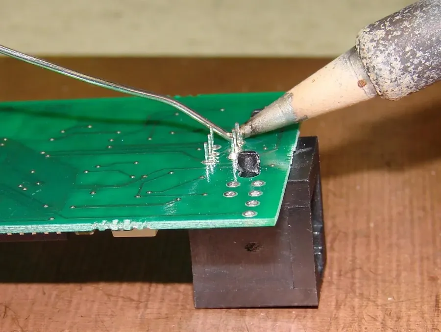
Strategically place components on the proto board to minimize wire lengths and reduce signal interference. Group related components together to ensure clean signal paths and improve overall circuit performance. This also simplifies troubleshooting and debugging. - Proper Soldering Techniques
Utilize correct soldering techniques to ensure robust electrical connections and prevent cold joints, which can cause intermittent failures. Employ a temperature-controlled soldering iron and use appropriate flux to achieve clean and reliable solder joints. Practice on spare boards to hone your soldering skills. - Wire Management
Employ high-quality wires and avoid excessive wire lengths. Use wire strippers to avoid damaging the wires, which can result in poor connections. Organize wires neatly to prevent shorts and facilitate easy tracing of connections, using wire ties or clips for better organization. - Workspace Organization
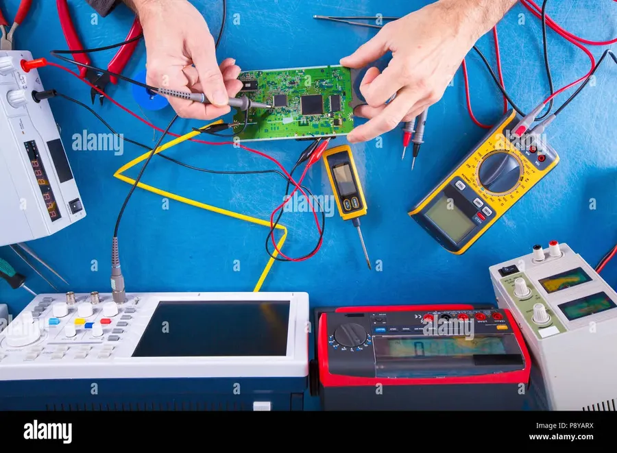
Maintain a clean and organized workspace to enhance efficiency and minimize errors. Use bins or drawers to store components, tools, and wires neatly. A well-organized workspace reduces distractions and enhances concentration during the assembly and debugging process. - Testing and Verification
Rigorously test and verify your circuit at each assembly stage. Use a multimeter to check continuity and voltage levels to identify and resolve any issues early. This iterative approach greatly reduces the complexity of debugging at the end of the design cycle. - Documentation
Document all aspects of your circuit, including the schematic, component layout, and wiring details. Maintain a clear record of any modifications or troubleshooting steps. This ensures consistency and assists future reference or design improvements.
Advanced Proto PCB Techniques: Beyond Simple Circuits
Venturing beyond basic circuits on proto PCBs unlocks the potential for more complex and functional prototypes. Advanced techniques enable the integration of surface mount components and the creation of intricate layouts, essential for modern electronic designs. These techniques, while demanding precision and skill, allow engineers to validate sophisticated designs without the commitment of custom PCB fabrication.
- Surface Mount Technology (SMT) on Proto Boards
Integrating SMT components onto proto boards requires techniques like using SMT breakout boards or adapters. Precise soldering with hot air reflow or fine-tipped soldering irons is crucial due to the small size of these components. SMT components allow for smaller circuit footprints and are essential for high-density designs. Consider using solder paste and a stencil for more accurate and consistent SMT component placement. - Multilayer Circuit Emulation on Proto Boards
While proto boards are primarily single or double-sided, techniques exist to emulate multilayer circuits. This involves strategically using jumper wires or insulated wire wraps to connect traces on different layers, or by stacking proto boards with interconnections. Careful planning and wire management are paramount to avoid shorts and signal integrity issues. - Utilizing Flexible Proto PCBs
Flexible proto PCBs can be useful for applications requiring non-rigid board shapes or for integrating circuitry into tight spaces. These require specialized handling due to their flexibility but enable unique prototype designs that traditional boards cannot accommodate. Flexible proto PCBs allow for bending and shaping to fit unique enclosures or mechanical designs, which adds another dimension to prototype capabilities. - Thermal Management Considerations
As circuit complexity increases, so does the need for thermal management. Adding heatsinks to proto PCBs is crucial. Employing thermal vias, where applicable, for heat dissipation helps ensure prototype boards operate safely and reliably, particularly when dealing with power-intensive circuits or when components are densely packed. Consider using thermal tape or adhesive to efficiently secure heatsinks. - High-Frequency Proto PCB Design
High-frequency circuits require careful proto board construction. Pay close attention to signal routing and impedance matching. Minimize parasitic capacitance and inductance. Utilize techniques such as ground planes to control signal integrity and reduce noise. High-speed signal traces should be as short and direct as possible, with careful component placement.
Proto PCB boards are indispensable tools in the electronics design and prototyping process. Whether you are working on a simple hobby project or a complex industrial design, understanding the different types of proto PCB boards and how to utilize them effectively is critical. By carefully considering your project's requirements and the various options available, you can streamline your development process, save time, and create better products. Investing in high quality proto pcb boards and best practices in their use will significantly improve your projects outcomes.