Decoding PCB Components: A Deep Dive for Beginners & Experts
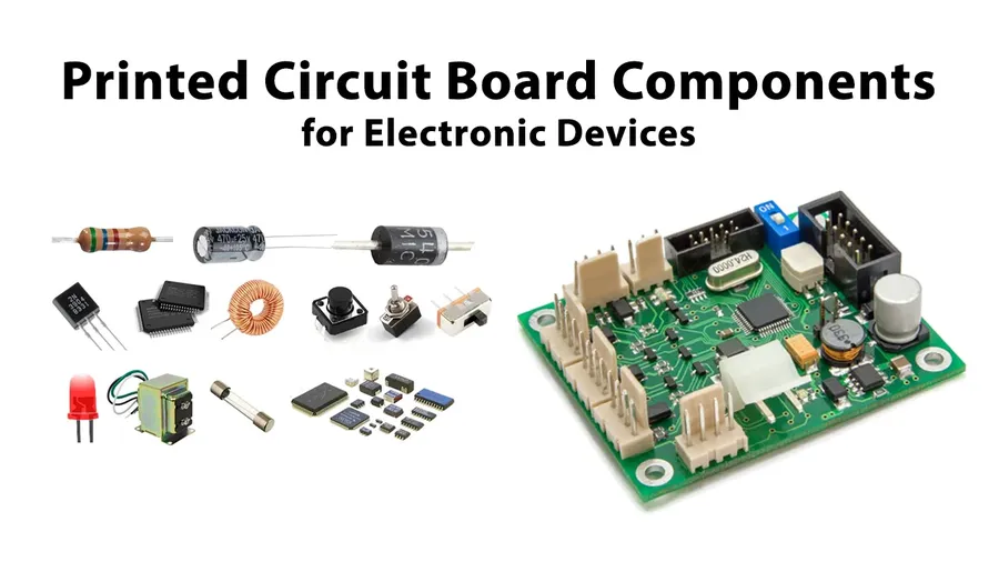
In our digitally-driven world, printed circuit boards (PCBs) are the unsung heroes, forming the backbone of nearly all electronic devices. From the smallest microchip in your phone to the complex control systems of industrial machinery, PCBs rely on a variety of crucial components. This article demystifies these essential building blocks, offering a clear and comprehensive guide suitable for both beginners and experienced engineers, emphasizing not just their presence, but their vital roles in every circuit.
The Core Functions of PCBs and Their Components
Printed Circuit Boards (PCBs) serve as the foundational platform for electronic devices, providing both mechanical support and electrical connections for various electronic components. Essentially, a PCB is a structured network that allows components to interact, enabling complex circuits to perform specific functions as designed. Without PCBs, the intricate connections required for modern electronics would be impractical to achieve.
At its core, a PCB facilitates two primary functions: the mechanical mounting of components and the electrical routing that allows these components to communicate and operate together. This is achieved through a combination of conductive pathways (traces), insulating materials, and connection points.
The interaction between components on a PCB is determined by the layout and routing of these conductive traces. These traces are precisely designed to ensure proper signal flow, preventing shorts and signal degradation. Different types of components—passive, active, connectors, etc.—are placed strategically to optimize the circuit's performance and functionality. Understanding these components, as detailed in subsequent sections, is essential to comprehending how PCBs function and how electronic devices operate.
Passive Components: The Foundation of Every Circuit
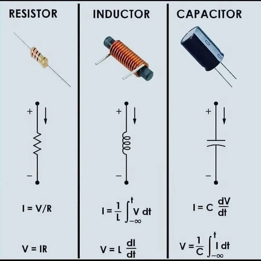
Passive components are fundamental building blocks of any electronic circuit, including PCBs. Unlike active components, they do not require an external power source to operate and cannot amplify or switch electronic signals. Instead, they modify signals through their inherent properties, primarily manipulating voltage, current, and impedance. Resistors, capacitors, and inductors are the core elements within this category, serving distinct but equally crucial roles in circuit functionality.
| Component | Symbol | Function | Key Parameters | Typical Applications |
|---|---|---|---|---|
| Resistor | Zigzag line or Rectangle | Limits current flow, divides voltage | Resistance (Ohms), Tolerance, Power Rating | Current limiting, voltage dividers, biasing circuits |
| Capacitor | Two parallel lines | Stores electrical charge, filters signals | Capacitance (Farads), Voltage Rating, Tolerance | Filtering, decoupling, energy storage |
| Inductor | Coil or series of loops | Stores energy in magnetic field, filters signals | Inductance (Henries), Current Rating, Quality Factor | Filtering, tuning circuits, chokes |
Understanding the role of each passive component is crucial for PCB design and analysis. Resistors regulate the flow of current and establish voltage levels within the circuit. Capacitors store electrical energy and are instrumental in filtering out unwanted signal frequencies. Inductors store energy in a magnetic field and are also used in filtering and energy storage applications. These components do not introduce gain or switching functionality and perform as defined by physical laws.
Active Components: The Control Centers of PCBs
Active components are the dynamic elements within a Printed Circuit Board (PCB), actively influencing current flow and enabling complex functions. Unlike passive components, which simply react to electrical signals, active components can amplify, switch, or otherwise manipulate these signals, forming the basis of all electronic processing and control. This section will explore the roles of key active components such as diodes, transistors, and integrated circuits (ICs).
| Component | Function | Description |
|---|---|---|
| Diodes | Current Direction Control | Allow current to flow primarily in one direction; used for rectification, signal detection, and voltage regulation. Different types of diodes exist, such as rectifiers, LEDs, and Zener diodes, each with specific characteristics. |
| Transistors | Switching and Amplification | Three-terminal semiconductor devices that can act as electronic switches or amplifiers. They are the fundamental building blocks of modern electronics, with types like BJTs and MOSFETs serving a multitude of roles, from signal amplification to logic gates. |
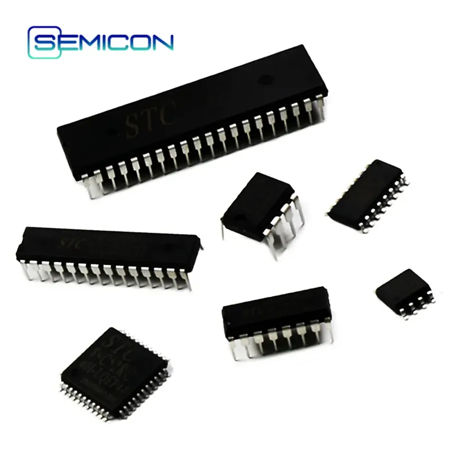
| Integrated Circuits (ICs) | Complex Function Execution | Miniaturized electronic circuits (also called chips) containing a large number of transistors and other components interconnected to perform specific functions, such as microprocessors, memory, amplifiers, and logic functions. They form the core of most complex electronics. |
Other Essential PCB Components and Their Uses
Beyond the fundamental active and passive components, numerous other specialized elements play vital roles in the functionality of a Printed Circuit Board (PCB). These components, while not always the core of the circuit, provide crucial connectivity, sensing capabilities, or specific electrical transformations that allow the PCB to perform its intended application.
- Connectors
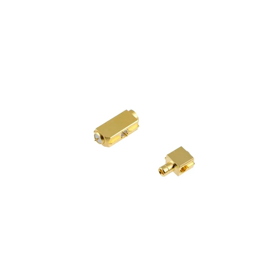
Connectors facilitate the transfer of signals and power between the PCB and external devices or other PCBs. They come in various types (e.g., headers, edge connectors, USB ports), each designed for specific applications and connection types. Their proper selection ensures reliable and durable physical and electrical connections. - Sensors
Sensors convert physical phenomena (e.g., temperature, pressure, light) into electrical signals. They enable PCBs to interact with their environment, providing feedback to control systems. Different sensor types are used depending on the application, such as temperature sensors in thermostats or pressure sensors in automotive systems. - Transformers
Transformers are used for stepping up or down voltages within a circuit, providing electrical isolation between different parts of the circuit or between the circuit and the power source. They are essential in power supply circuits to adapt incoming power to the specific needs of the PCB's components. - Potentiometers
Potentiometers are variable resistors that allow for manual or automatic adjustment of resistance. They are commonly used in circuits that require adjustable voltage or current levels. Typical uses include volume controls, calibration adjustments, or sensor adjustments - Crystals and Oscillators
These components generate precise clock signals that synchronize the operation of digital circuits. Crystals provide a stable frequency reference and are used in conjunction with oscillator circuits, ensuring consistent timing and operation within the PCB. - Fuses
Fuses are safety devices that protect circuits from overcurrent conditions. They are designed to fail (melt and open the circuit) when the current exceeds a specified limit, preventing damage to more expensive components. Proper fuse selection is critical for preventing fire and safety risks.
PCB Component Identification: Decoding Markings and Symbols
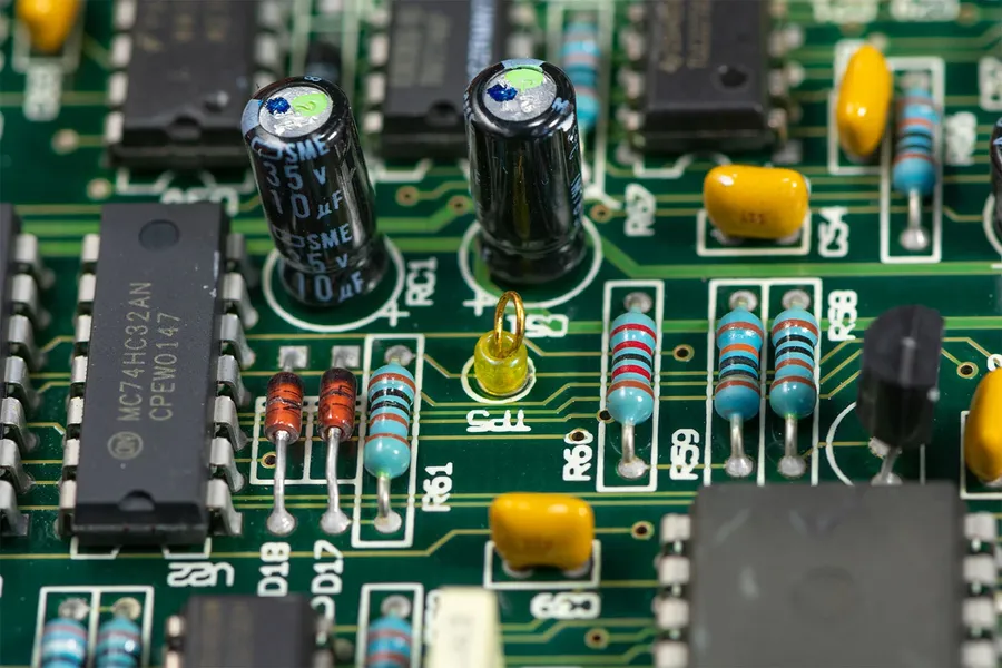
Accurate identification of PCB components is crucial for effective troubleshooting, repair, and design modification. This section details how to decode the markings, symbols, and codes found on various electronic components, thereby enhancing your ability to work with PCBs.
The identification process involves understanding component markings, which often include manufacturer logos, part numbers, date codes, and electrical specifications (e.g., resistance, capacitance, voltage ratings). These markings can be read directly on the component body or from accompanying datasheets. Understanding schematic symbols is equally important; these represent components in circuit diagrams, which provide a functional view of the PCB.
| Component Type | Typical Markings | Schematic Symbol Example | Key Identification Features |
|---|---|---|---|
| Resistor | Color bands (EIA code), resistance value, tolerance | Zigzag line | Color bands indicate resistance; numeric value codes |
| Capacitor | Capacitance value (numeric or alphanumeric), voltage rating, tolerance | Two parallel lines | Numeric values indicate capacitance; polarity indicated on some types |
| Inductor | Inductance value, physical size and shape | Coiled wire | Often marked with inductance value or a numerical code. |
| Diode | Part number, cathode marking | Triangle pointing to a bar | Bar indicates cathode; alphanumeric code specifies type |
| Transistor | Part number, manufacturer logo | Three lines with arrows or symbols | Alphanumeric code indicates type; package indicates function |
| Integrated Circuit (IC) | Part number, manufacturer logo, date code | Rectangle with pins | Part number specifies function; pin configuration is critical |
Proper component identification also requires knowledge of international standards, such as the EIA (Electronic Industries Alliance) color code for resistors and the standard symbols defined by IEEE (Institute of Electrical and Electronics Engineers). Component datasheets, provided by manufacturers, are an invaluable resource for detailed specifications and pin-out information.
Selecting the Right Components: Factors to Consider
Selecting the appropriate PCB components is crucial for ensuring the reliable and efficient operation of any electronic device. This decision process requires a thorough understanding of various electrical, environmental, and mechanical factors. Choosing components that precisely meet the design specifications prevents premature failure, optimizes performance, and minimizes the risk of catastrophic issues.
| Factor | Description | Importance |
|---|---|---|
| Voltage Rating | The maximum voltage a component can safely handle without breakdown. | Critical for preventing component failure due to overvoltage. |
| Current Rating | The maximum current a component can continuously conduct without overheating. | Essential for preventing thermal damage and ensuring long-term reliability. |
| Power Rating | The amount of power (measured in watts) a component can dissipate safely. | Important for managing heat generated during circuit operation and preventing component damage due to excess heat. |
| Tolerance | The permissible variation from the specified nominal value of a component. | Affects circuit accuracy and stability, particularly in precision applications. |
| Thermal Characteristics | The component's ability to handle heat generation and dissipation, including thermal resistance and operating temperature range. | Crucial for reliability, particularly in high-power or high-temperature environments. |
| Operating Frequency | The range of frequencies at which a component can operate effectively. | Vital for signal integrity and performance in high-frequency applications. |
| Physical Size and Package | Dimensions and packaging of the component, which affects PCB layout and assembly. | Influences design density, manufacturability, and component placement options. |
| Environmental Conditions | Operating temperature range, humidity, and other environmental factors the component can tolerate. | Essential for ensuring the reliability of devices used in harsh or variable conditions. |
| Material Compatibility | Ensuring the component materials are compatible with other PCB materials and manufacturing processes. | Prevents corrosion, delamination, and other manufacturing-related problems. |
| Cost | The price of the component and the effect it will have on the overall cost of the product. | Must be balanced with the performance and reliability required for the application. |
| Datasheet Specifications | Detailed characteristics and performance parameters from the component's technical datasheet. | The foundation for accurate design and component selection; must be carefully reviewed before design |
Common PCB Component Failure Points and Troubleshooting Tips
Understanding common failure modes in PCB components is crucial for effective troubleshooting and maintenance. This section delves into the typical causes of component failure and offers practical diagnostic and repair advice, emphasizing the use of a multimeter for accurate assessments.
The following are some key areas to focus on when troubleshooting PCB components:
- Overheating
Excessive heat, often caused by overcurrent or inadequate cooling, can damage components, leading to performance degradation or complete failure. Signs include discoloration, bulging, or a burnt smell near the component. - Overvoltage
Exposing components to voltages beyond their rated specifications can cause immediate damage or long-term degradation. This often manifests as short circuits or open circuits within the component. - Physical Damage
Impacts, bending, or other physical stress can crack components, damage internal connections, or create shorts and opens. Visible cracks or broken leads are obvious indicators. - Incorrect Installation
Incorrect component placement or orientation (especially with polarized components like diodes and electrolytic capacitors) can lead to improper circuit function and subsequent component failure. Always double check datasheet specifications for proper installation. - Environmental Factors
Exposure to moisture, corrosive materials, or extreme temperatures can lead to component degradation, corrosion, or malfunction over time. Verify storage and operational conditions meet manufacturer's recommendations. - Aging and Wear
Components, especially electrolytic capacitors, have a finite lifespan and will degrade over time due to natural wear and tear of the materials. Reduced capacitance or increased ESR can be symptoms of aging. - Electrostatic Discharge (ESD)
ESD can damage sensitive components, particularly semiconductors like ICs and transistors. Always use proper ESD protection during handling and assembly.
Below are general steps for troubleshooting using a multimeter:
- Visual Inspection
Carefully inspect the PCB for any visible signs of damage, such as burnt components, cracked solder joints, or lifted traces. Compare with a known good board if possible. - Power Off and Discharge Capacitors
Ensure the circuit is powered off before testing any components, and discharge capacitors to avoid accidental shocks and inaccurate readings. A discharge resistor may be required for larger capacitors. - Component Testing with Multimeter
Use the multimeter to test specific components based on the symptoms. For example, check resistors for their rated resistance, capacitors for capacitance and shorts, diodes for forward voltage drop, and transistors for their operational functionality. Refer to component datasheets for expected values. - Circuit Continuity Testing
Use the multimeter's continuity test function to check for breaks in traces or shorts between adjacent conductors on the PCB. Ensure you are testing isolated sections of the circuit by powering off and disconnecting power, and that capacitors have been discharged - Voltage and Current Measurements
Use the multimeter to measure voltage and current values at various points on the circuit to verify that the voltages, and current are within the design parameters. - Replace Faulty Components
Once a faulty component is identified, remove it carefully and replace with a new one. Ensure correct polarity and values when replacing polarized components like electrolytic capacitors, and use the correct solder temperature to avoid thermal shock. - Re-test
After replacing components, re-test the circuit to confirm that the issue has been resolved.
By understanding these common failure points and employing systematic troubleshooting techniques, you can effectively diagnose and repair issues within your PCB, minimizing downtime and maximizing component lifespan.
Frequently Asked Questions About PCB Components
This section addresses common inquiries regarding PCB components, their operational roles, and their integration within a circuit board. Understanding these FAQs can help both beginners and experienced professionals in electronics design and troubleshooting.
- What are the fundamental components found on a PCB?
PCBs incorporate a variety of components, broadly categorized as passive and active. Passive components, such as resistors, capacitors, and inductors, manage electrical energy. Active components, like diodes, transistors, and integrated circuits (ICs), control and process electrical signals. Additionally, connectors, sensors, and transformers are vital for specific functions within a circuit. - What does a PCB actually consist of in terms of materials and structure?
A PCB primarily consists of a non-conductive substrate material, often fiberglass reinforced epoxy laminate, onto which conductive traces are etched. These traces, typically made of copper, form the electrical pathways. Components are then soldered onto the board, and multiple layers of conductive and non-conductive material can be stacked together to increase circuit density and functionality. The board may also include solder masks and silkscreen layers for insulation and identification. - What is the meaning of 'PCB' and its significance in electronics?
PCB stands for Printed Circuit Board. It's a fundamental building block in electronics, providing the mechanical support and electrical connections for electronic components. PCBs allow for organized, reliable, and efficient assembly of circuits, facilitating the production of a wide range of electronic devices. Without PCBs, electronic systems would be far more bulky, unreliable and difficult to manufacture. - What are the different types of PCB testing methods to ensure component functionality?
PCB testing methods include visual inspection, in-circuit testing (ICT), flying probe testing, functional testing, automated optical inspection (AOI), X-ray inspection, and environmental testing. These methods ensure that components are placed correctly, functioning as intended, and that the board meets performance and reliability standards. Each test has a specific application, with some focusing on individual component values and connections while others test the board as a functional unit. - How do I identify different types of PCB components visually?
Component identification is typically achieved through a combination of visual inspection, markings, and schematic symbols. Resistors are often color-coded, capacitors may have values and voltage ratings printed on their bodies, and ICs have part numbers. Schematics provide standard symbols to represent each component type. Referencing component datasheets and online resources can aid in precise identification of specific component models. - What are some common failure points for components on PCBs?
Common failure points include overheating due to excess current, damage from electrostatic discharge (ESD), mechanical stress from physical shock, and corrosion from exposure to moisture. Component failures often manifest as a result of manufacturing defects, aging, or exposure to harsh operating conditions. Careful design, testing and environmental controls can mitigate these common failure causes. - What is the best approach for troubleshooting components on a PCB?
Troubleshooting begins with visual inspection for obvious issues like burnt components or broken solder joints. A multimeter is crucial for measuring voltage and resistance, which can reveal if a component is shorted or open. Following the circuit diagram can help isolate faulty sections. In many instances, component replacement can be the most efficient method to correct the faulty connection. Detailed documentation can help to identify the root cause for a problem.
Future Trends in PCB Components: Miniaturization and Innovation
The landscape of PCB components is constantly evolving, driven by the demand for smaller, more efficient, and more powerful electronic devices. Miniaturization, surface mount technology (SMT), and the development of advanced materials are at the forefront of these innovations, promising significant advancements in the capabilities and applications of PCBs.
- Miniaturization
The relentless push for smaller devices necessitates a reduction in component size. This trend leads to the development of increasingly compact components, which in turn require more precise manufacturing processes. Benefits include reduced device size, improved portability, and increased circuit density. - Surface Mount Technology (SMT)
SMT is a method where components are mounted directly onto the surface of the PCB, rather than being inserted through holes. This technology enables higher component densities, faster production speeds, and reduced board thickness. SMT components are typically smaller and lighter than their through-hole counterparts, contributing to further miniaturization. - Advanced Materials
The performance of PCB components is increasingly dependent on the materials used in their construction. Researchers are developing new materials with superior electrical conductivity, thermal management, and mechanical strength. Examples include high-performance polymers, ceramic composites, and graphene-based materials.
- Emerging Trends in Component Design
Beyond miniaturization, SMT and advanced materials, other emerging trends are also shaping the future. These include the development of integrated passive devices (IPDs), which combine multiple passive components into a single package, and the increasing use of flexible PCBs, which can conform to curved surfaces and allow for new form factors. Furthermore, the use of 3D printing techniques is being explored for the fabrication of complex and custom PCB components.
Understanding PCB components is crucial for anyone working with electronics, from hobbyists to professional engineers. This guide provides a comprehensive overview of essential components, their functions, and how they contribute to the overall performance of PCBs. By mastering these fundamentals and anticipating future developments, you will be well-equipped to handle today's electronic challenges and prepare for tomorrow's innovations. PCB components are the cornerstones of modern electronics, and a thorough understanding of them is essential for both effective design and maintenance.