FR4: The Ultimate Guide to PCB Material
In today's fast-paced world of electronics, the backbone of almost every device lies in printed circuit boards (PCBs). And at the heart of many PCBs, we find FR4. Like the frame of a building, FR4 provides the structural support for complex electronic circuits. This material, a composite of fiberglass and epoxy resin, is ubiquitous for good reason. In this guide, we will explore the properties of FR4, its advantages and disadvantages, and what makes it such a popular choice for PCB manufacturing. We will delve into its applications, specifications and answer any questions you might have about this common yet essential component.
Understanding FR4: What is it?
FR4, a ubiquitous material in printed circuit board (PCB) manufacturing, is a composite laminate primarily composed of woven fiberglass cloth and a flame-retardant epoxy resin. This specific combination results in a material with a unique balance of mechanical, electrical, and thermal properties, making it exceptionally suitable for a broad range of applications. The designation 'FR4' signifies that the material meets specific flammability standards, ensuring its safe use in various electronic devices.
Key Properties of FR4 Material
FR4's widespread use in printed circuit boards (PCBs) stems from its well-balanced set of properties. These include its dielectric constant, thermal behavior, mechanical strength, and flame retardancy, each playing a crucial role in the performance and reliability of electronic devices. These characteristics are paramount for design considerations and are the primary reason for FR4's broad acceptance in the electronics industry.
| Property | Typical Value | Significance |
|---|---|---|
| Dielectric Constant | 3.8 - 4.8 @ 1 MHz | Influences signal speed and impedance; Lower values reduce signal distortion. |
| Dissipation Factor (Tan δ) | 0.02 or less @ 1 MHz | Affects signal loss at high frequencies; Lower values reduce signal attenuation. |
| Glass Transition Temperature (Tg) | 130 - 180 °C (standard to high Tg) | Determines the maximum operating temperature before material properties degrade; higher Tg for more demanding applications. |
| Thermal Conductivity | 0.25 - 0.3 W/m·K | Affects heat dissipation; lower thermal conductivity means more heat is retained by the PCB. |
| Flexural Strength | Typically 250-400 MPa | Indicates the material's resistance to bending; higher strength for greater durability |
| Tensile Strength | Typically 200-350 MPa | Indicates the material's resistance to stretching; higher strength for greater durability. |
| Flame Retardancy | UL94 V-0 | Indicates the material's ability to self-extinguish in the event of a fire; V-0 is the highest rating. |
| Water Absorption | 0.1-0.2% after 24 hrs | Impacts dielectric properties and mechanical stability; low values are essential for consistent performance. |
The dielectric constant of FR4, typically between 3.8 and 4.8 at 1MHz, is crucial for determining the impedance of signal traces and how signals propagate through the board. The dissipation factor, or loss tangent, which is typically 0.02 or less at 1MHz, is responsible for signal loss at higher frequencies, influencing signal integrity, particularly in high-speed applications. The thermal properties, such as the glass transition temperature (Tg), which varies from 130 to 180 degrees C depending on the type, dictate the operating temperature limits before the material properties degrade. The thermal conductivity of FR4, ranging from 0.25-0.3 W/m·K, impacts the PCB's ability to dissipate heat generated by electronic components. FR4 also offers considerable mechanical strength, with flexural strength ranging between 250 and 400 MPa and tensile strength from 200-350MPa which ensures the board will withstand stress and pressure during assembly and operation. The inherent flame retardancy, rated at UL94 V-0, ensures that the material will self-extinguish when exposed to flames, and the low moisture absorption helps maintain stable electrical properties. Understanding these key properties allows for a more strategic and informed design for PCB applications.
The Manufacturing Process of FR4 PCBs
The creation of FR4 PCBs is a multi-stage process that transforms raw materials into functional circuit boards. This process involves layering fiberglass cloth with resin, followed by lamination, and the application of copper circuitry. The process requires precision and control to ensure the final board meets performance specifications.
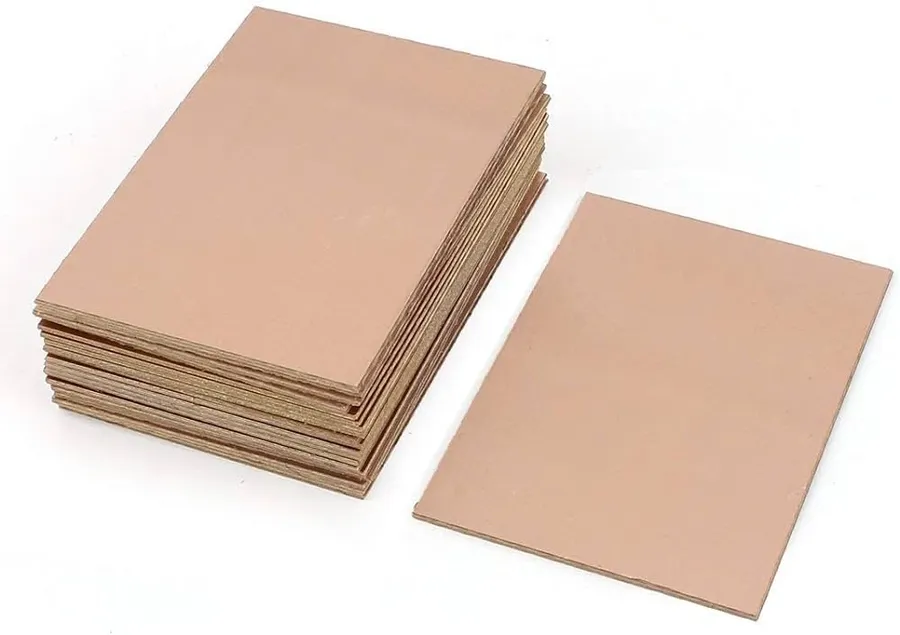
- Preparation of the FR4 Laminate
The process begins with woven fiberglass cloth, which is impregnated with a flame-retardant epoxy resin. This combination forms the base material of FR4. The fiberglass provides mechanical strength, while the resin binds the structure and provides electrical insulation. - Lamination
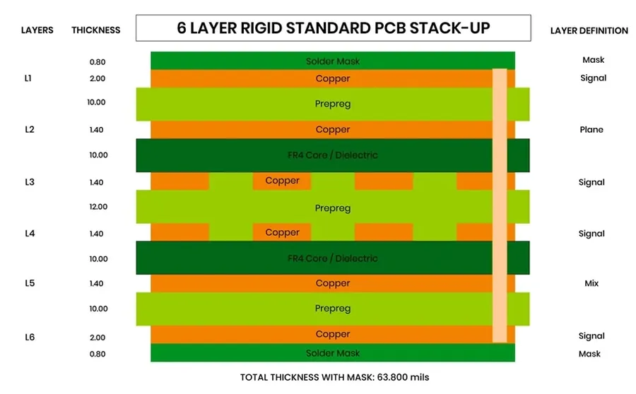
Multiple layers of the resin-impregnated fiberglass cloth, along with copper foil, are stacked together. This stack is then subjected to high temperature and pressure. This lamination process fuses the layers, creating a solid, multi-layered laminate of FR4 with copper bonded to its surfaces. - Copper Patterning
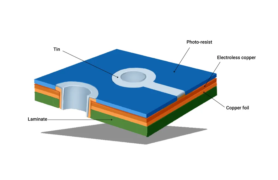
The copper foil bonded to the FR4 substrate is then patterned to create the circuit traces. This is typically achieved using photolithography, where a photoresist material is applied, exposed to UV light through a mask, and then etched to remove the unwanted copper, leaving behind the desired circuit traces. - Drilling and Via Creation
Holes are drilled through the PCB for mounting components and creating vias (interlayer connections). These vias are often plated with copper to ensure electrical conductivity between different layers of the board. - Solder Mask Application
A solder mask is applied over the board, covering the copper traces and leaving only the solderable pads exposed. This protects the traces from oxidation and prevents solder bridging during the assembly process. - Surface Finishing
A final surface finish is applied to the exposed copper pads, which improves solderability. Common surface finishes include HASL (Hot Air Solder Leveling), ENIG (Electroless Nickel Immersion Gold) and others. - Profiling and Testing
The boards are profiled or cut out from the laminate to the required shape and size. Finally, each board undergoes electrical testing to ensure its functionality and compliance with design specifications.
Advantages of Using FR4 in PCB Design
FR4's widespread adoption in printed circuit board (PCB) manufacturing stems from a confluence of advantageous properties. Its cost-effectiveness, excellent electrical insulation, commendable mechanical strength, and broad availability make it a compelling choice for a vast range of PCB applications. These attributes collectively provide a balance of performance and economic viability unmatched by many alternative materials.
| Advantage | Description | Impact on PCB Design |
|---|---|---|
| Cost-Effectiveness | FR4 is relatively inexpensive compared to specialized materials. | Reduces overall manufacturing costs, enabling wider accessibility for various applications. |
| Excellent Electrical Insulation | FR4 provides high resistance to electrical current flow, preventing short circuits and signal leakage. | Ensures reliable signal transmission and minimizes interference. |
| Good Mechanical Strength | FR4 exhibits good flexural and tensile strength, providing mechanical integrity to the PCB. | Enables robust PCBs that can withstand mechanical stress. |
| Wide Availability | FR4 is readily available from numerous suppliers globally. | Shortens lead times and simplifies procurement, making it more accessible. |
| Flame Retardancy | FR4 is self-extinguishing and meets UL94 V-0 standards, preventing fire hazards. | Enhances safety for both the user and the device. |
Disadvantages and Limitations of FR4
While FR4 is a ubiquitous and cost-effective material for PCB fabrication, it's crucial to acknowledge its inherent limitations, particularly when performance demands are high. These limitations primarily stem from its material properties that affect electrical and thermal characteristics at high frequencies.
Understanding these drawbacks will assist in making informed decisions on when to use FR4 or consider alternative materials for optimized circuit board functionality and reliability.
- Relatively High Dielectric Constant:
FR4's dielectric constant, typically ranging from 3.8 to 4.8, is higher compared to some specialized materials. This can lead to signal degradation and impedance mismatches, particularly in high-speed digital or RF applications. - Increased Signal Loss at Higher Frequencies:
The dielectric loss tangent of FR4 increases with frequency, leading to more significant signal attenuation at higher operating frequencies. This is a crucial consideration in RF and microwave applications where signal integrity is paramount. Data and case studies indicate that at frequencies above a few GHz, FR4 can exhibit substantial losses, resulting in performance degradation compared to materials with lower loss tangents. - Thermal Limitations:
While FR4 exhibits adequate thermal stability for many applications, it has a limited maximum operating temperature before its properties begin to degrade. It also has relatively low thermal conductivity, which can result in increased component temperatures and potential reliability issues. For applications where substantial heat generation is expected, better thermal management may be required, potentially increasing complexity and cost. - Moisture Absorption:
FR4 is prone to absorbing moisture, which can alter its dielectric constant and loss tangent. This change can lead to unpredictable electrical performance. The absorbed moisture can also affect the mechanical integrity of the board, especially in high-humidity environments or during reflow soldering processes, creating potential long-term reliability concerns. - Dimensional Instability:
FR4 can expand and contract with changes in temperature and humidity which leads to dimensional instability. This dimensional instability can cause stress on components and solder joints, increasing the risk of failure. In precision designs, this change must be accounted for during manufacturing processes.
FR4 vs. Other PCB Materials
While FR4 stands as the most commonly used material in PCB manufacturing, it's essential to understand how it compares with other available options. This section provides a detailed comparison of FR4 with materials like polyimide, CEM-1, and Rogers materials, focusing on their cost, performance, and suitable applications. This comparison will empower designers to make well-informed choices based on their specific project requirements.
| Material | Cost | Dielectric Constant | Loss Tangent | Thermal Performance | Mechanical Strength | Typical Applications |
|---|---|---|---|---|---|---|
| FR4 | Low to Moderate | 3.8-4.8 | 0.02 at 1 GHz | Moderate | Good | General-purpose PCBs, consumer electronics |
| Polyimide | High | 3.0-3.5 | 0.002-0.004 at 1 GHz | Excellent (High Tg) | Excellent | High-temperature, aerospace, flexible circuits |
| CEM-1 | Low | 4.2-4.6 | 0.025 at 1 GHz | Poor | Moderate | Single-sided, low-cost applications |
| Rogers Materials | Very High | 2.2-3.6 | 0.0001-0.002 at 10 GHz | Good to Excellent | Good | High-frequency, RF, and microwave circuits |
**Detailed Comparison Points:** * **Cost**: FR4 offers an excellent balance between performance and price, making it a cost-effective choice for many applications. CEM-1 is at the lower end of the cost spectrum, however, it has significant limitations in performance. Polyimide and Rogers materials, on the other hand, are significantly more expensive due to their superior performance characteristics. * **Dielectric Constant**: FR4's dielectric constant, typically ranging from 3.8 to 4.8, is suitable for most digital and analog applications but may be a limiting factor in high-frequency applications. Polyimide offers a lower and more stable dielectric constant, making it suitable for high-speed signals. Rogers materials, designed for high-frequency applications, have a lower and more stable dielectric constant than both FR4 and polyimide, often falling in the 2.2 to 3.6 range. * **Loss Tangent**: The loss tangent, which indicates signal loss, is an important parameter at high frequencies. FR4's loss tangent is relatively high compared to polyimide and Rogers, leading to signal degradation at higher frequencies. Polyimide and Rogers offer much lower loss tangents, crucial for RF and microwave circuits. * **Thermal Performance**: FR4 has moderate thermal performance, suitable for typical operating conditions. Polyimide has excellent thermal properties and high glass transition temperature (Tg), making it suitable for high-temperature environments. Rogers also has good to excellent thermal performance, depending on the specific formulation. * **Mechanical Strength**: All of these materials exhibit good mechanical strength. FR4 is a rigid material and it offers good structural integrity for most applications. Polyimide has excellent mechanical strength and flexibility, which makes it ideal for flexible circuit boards. CEM-1 is less strong than FR4 or Polyimide. * **Applications**: FR4 is ideal for a wide range of general-purpose applications, including consumer electronics, industrial control systems, and simple digital circuits. Polyimide is utilized in aerospace, high-temperature applications, and flexible electronics. Rogers materials excel in high-frequency applications such as RF circuits, microwave devices, and telecommunication equipment. CEM-1 is often used in low-cost, single-sided PCBs. **Conclusion:** The choice of PCB material is heavily dependent on the specific requirements of the application. While FR4 provides a versatile and cost-effective solution for many general applications, more demanding applications requiring higher frequencies, temperatures, or flexible designs require materials such as Polyimide or Rogers. Understanding these differences is essential for designers to choose the most suitable material for their projects.
Frequently Asked Questions About FR4 Material
This section addresses common queries regarding FR4, a widely used material in printed circuit board (PCB) manufacturing. We aim to provide clear and concise answers to help you better understand its properties, applications, and limitations.
- What does FR4 stand for?
FR4 stands for 'Flame Retardant 4'. It is a NEMA (National Electrical Manufacturers Association) grade designation for a composite material composed of woven fiberglass cloth impregnated with a flame-retardant epoxy resin binder. This material is not just 'flame resistant,' but has a specific flame retardancy rating. - Why is FR4 so widely used in PCBs?
FR4's popularity stems from its excellent balance of properties and cost-effectiveness. It offers good electrical insulation, high mechanical strength, flame retardancy, and is relatively easy to manufacture. These factors make it a suitable choice for a wide range of PCB applications. Its cost relative to performance is a major driving factor in its adoption. - What are the primary disadvantages of FR4?
While widely used, FR4 does have limitations. Its relatively high dielectric constant (typically 3.8 to 4.8) and dielectric loss can affect signal integrity at high frequencies, resulting in signal attenuation and distortion. Additionally, its thermal conductivity is not ideal, which can cause heat management issues in high-power applications. These limitations must be considered for high performance, high-frequency circuits. - How does the dielectric constant of FR4 affect PCB design?
The dielectric constant of FR4 dictates how electric fields propagate within the material. A higher dielectric constant, such as the 3.8 to 4.8 range of FR4, can lead to signal propagation delay and impedance changes. This must be carefully considered in high-speed circuit design to ensure signal integrity, requiring designers to match impedances and account for dielectric losses which are also frequency-dependent. - What is the difference between G-10 and FR4?
G-10 and FR4 are both fiberglass epoxy laminates but G-10 is not flame retardant. FR4 is essentially a flame-retardant version of G-10. This key distinction makes FR4 the standard choice for PCBs where flame resistance is critical. While G-10 is still used in various other electrical and structural applications where fire resistance isn't required, FR4 is preferred for PCBs to meet safety standards and regulations. - Is FR4 suitable for high-frequency applications?
FR4 can be used for high-frequency applications to a certain extent, however its performance degrades with increasing frequency. For demanding high-frequency applications, such as those above a few GHz, other materials with lower dielectric constants and losses, such as Rogers materials or specialized laminates, may be better alternatives. The limitations of FR4's dielectric losses become significant at these higher frequencies. - What are the typical thickness options for FR4 PCBs?
Standard FR4 PCB thicknesses range from 0.2mm to 3.2mm, with the most common being 1.6mm. The appropriate thickness choice depends on mechanical, electrical, and thermal requirements. Thinner boards can allow for tighter designs and increased flexibility, while thicker boards provide increased durability and strength. This thickness directly impacts thermal properties and impedance.
Applications of FR4 in Various Industries
FR4's versatility and favorable properties make it a cornerstone material across a wide spectrum of industries. Its balance of electrical insulation, mechanical strength, and cost-effectiveness allows it to facilitate diverse applications ranging from everyday consumer products to high-performance industrial and critical medical devices.
- Consumer Electronics
FR4 is extensively used in the production of printed circuit boards for smartphones, tablets, computers, and various other consumer electronics. Its affordability and ease of processing make it ideal for high-volume manufacturing. - Industrial Equipment
In industrial settings, FR4 PCBs are integral components in control systems, power supplies, and automation machinery. Its durability and reliability are crucial for withstanding the harsh environments often encountered in industrial applications. - Aerospace
Although more specialized materials may be required for extreme conditions, FR4 finds use in avionics systems, control panels, and various electronic subsystems within aircraft. The balance of properties and cost-effectiveness is important in many non-critical aerospace applications. - Medical Devices
FR4 is used in a wide range of medical equipment, from diagnostic tools to patient monitoring systems. Its reliability and compatibility with various sterilization techniques are critical factors. - Automotive Electronics
FR4 is crucial in automotive electronics such as engine control units (ECUs), infotainment systems, and driver-assistance systems. Its capacity to handle a wide range of temperatures and vibrations is essential for its functionality in automotive applications. - Telecommunications
FR4 is a common material for circuit boards in telecommunication equipment, including routers, switches, and base stations. Its reliable electrical performance and low cost makes it suitable for such infrastructure. - Lighting
FR4 is widely used in LED lighting systems and control circuits for both residential and commercial applications due to its excellent insulating properties and mechanical stability.
Choosing the Right FR4 Thickness for Your PCB Design
Selecting the appropriate FR4 thickness is a crucial step in PCB design, directly impacting the board's mechanical integrity, electrical performance, and overall functionality. The choice depends on various factors including component size, weight, flexibility requirements, and the intended application environment.
A thinner board, for example, offers increased flexibility, which is beneficial for applications that involve bending or flexing. It can also help reduce weight, which is critical in portable devices or in aerospace application. However, thinner FR4 will generally compromise on mechanical strength and may require additional support to prevent damage. A thicker board, conversely, provides increased rigidity and better mechanical stability, making it ideal for applications where structural integrity is paramount, however it is heavier and may result in reduced flexibility.
| FR4 Thickness | Typical Application | Advantages | Disadvantages |
|---|---|---|---|
| 0.2 mm - 0.6 mm | Highly flexible PCBs, wearable devices | High flexibility, low weight | Low mechanical strength, challenging to manufacture |
| 0.8 mm - 1.2 mm | General-purpose PCBs, consumer electronics | Good balance of flexibility and rigidity, moderate weight | May not be ideal for very high-stress or very flexible applications |
| 1.6 mm | Standard for robust PCB, industrial electronics | High mechanical strength, wide availability | Higher weight, less flexible |
| 2.0 mm - 3.2 mm | High-stress application, backplanes, heavy-duty equipment | Exceptional structural integrity, heavy components | High weight, low flexibility, limited availability for some designs |
In addition to standard thicknesses, non-standard thicknesses of FR4 can be specified to fulfill particular requirements. Non-standard thicknesses are more expensive and often require a custom order. It is good practice to always consult with your PCB manufacturer to ensure that the required thickness can be manufactured cost effectively and according to the required tolerances.
Future Trends in FR4 Technology
The evolution of FR4 technology is driven by the increasing demands of modern electronics, which require higher performance, greater reliability, and improved signal integrity. Ongoing research and development efforts are focused on addressing existing limitations and enhancing FR4's capabilities to meet future needs.
Key areas of advancement include the reduction of dielectric loss at higher frequencies, increased thermal conductivity, and improved mechanical strength. These developments aim to expand the range of applications for FR4 while maintaining its cost-effectiveness.
- Lower Dielectric Loss Materials
Efforts are underway to reduce the dielectric loss of FR4, particularly at higher frequencies. The goal is to minimize signal degradation, allowing for the use of FR4 in high-speed applications, such as 5G and advanced communication systems. - Enhanced Thermal Performance
Research is focusing on developing FR4 materials with higher thermal conductivity. This improvement facilitates better heat dissipation in densely packed electronic circuits, crucial for maintaining reliability and performance. This is especially beneficial for high power and high-frequency applications. - Improved Mechanical Strength
Ongoing research is focused on improving the mechanical properties of FR4, including bending strength and impact resistance, to meet more demanding application requirements. This enhances the durability and longevity of electronic devices, making them more robust in harsh environments. - Integration of Nanomaterials
The incorporation of nanomaterials into the FR4 matrix is being explored to enhance various properties, such as mechanical strength, thermal conductivity, and dielectric performance, This leads to a performance boosts and new possibilities for material characteristics. - Environmentally Friendly Options
There is a growing trend towards developing more sustainable and eco-friendly FR4 materials. This encompasses the use of bio-based resins and more environmentally friendly manufacturing processes, aligning with the industry's movement towards more green technologies.
These trends indicate that FR4 will continue to be a prominent material in PCB manufacturing, evolving to meet future technological challenges while retaining its advantages of cost-effectiveness and versatility. As these improvements become more widely adopted, the performance limits of FR4 based PCBs will be pushed, leading to broader applications and new innovative design possibilities.
FR4 has become the workhorse of the electronics industry due to its balance of cost, performance, and availability. Its unique composition of fiberglass and epoxy resin, results in a material that is both electrically insulating and structurally robust. Understanding the properties, advantages, and limitations of FR4 is crucial for designing reliable and cost-effective PCBs. As technology continues to advance, ongoing improvements in FR4 will make it remain a relevant material in the electronic world. Whether you're an experienced engineer or just starting, understanding FR4 will help your journey with printed circuit boards.