Illuminating the World: A Comprehensive Guide to LED PCB Boards
In our increasingly illuminated world, the LED PCB board quietly powers much of what we see. From the screen you're reading this on to the streetlights guiding you home, these circuit boards are critical to efficient and effective lighting. This guide will demystify LED PCBs, exploring their construction, uses, and how they're revolutionizing modern lighting.
Understanding LED PCB Boards: The Basics
An LED PCB board serves as the foundational platform for LED lighting systems, providing both mechanical support and electrical connectivity for light-emitting diodes (LEDs). Essentially, it’s a printed circuit board (PCB) specifically designed to host and power LEDs for various lighting applications. The abbreviation PCB stands for Printed Circuit Board, which is a non-conductive material that has conductive pathways (traces) etched on its surface to form an electrical circuit. These pathways enable electricity to flow from a power source to the LEDs, causing them to illuminate. In the context of LEDs, a PCB board allows for the efficient and reliable operation of these light sources.
Types of LED PCB Boards: A Detailed Overview
LED PCB boards are the foundation of modern LED lighting solutions, and their diverse applications necessitate various design types. These designs range from simple single-layer boards to complex multi-layer and flexible substrates, each offering unique advantages tailored to specific operational requirements and environmental conditions. Understanding these types is crucial for selecting the correct board for any LED lighting project.
| Type of LED PCB Board | Description | Advantages | Disadvantages | Common Applications |
|---|---|---|---|---|
| Single-Layer PCB | Consists of a single layer of conductive material on one side of the dielectric substrate. | Simple design, low cost, easy to manufacture. | Limited circuit complexity, not ideal for high-density applications. | Simple LED indicators, basic lighting applications |
| Double-Layer PCB | Features conductive material on both sides of the substrate, connected through vias. | Increased circuit density, more routing options compared to single-layer PCBs. | More expensive and complex than single-layer boards. | General lighting, automotive lighting |
| Multi-Layer PCB | Consists of three or more layers of conductive material, separated by dielectric layers. | High circuit density, suitable for complex designs, excellent signal integrity | More complex and expensive to manufacture. | Advanced LED lighting systems, high-performance electronics |
| Flexible PCB (Flex PCB) | Made of flexible substrate materials like polyimide or polyester. | Can be bent or folded to fit in tight spaces, lightweight. | Can be more expensive than rigid PCBs, delicate, complex manufacturing. | Wearable electronics, curved displays, automotive lighting |
| Rigid-Flex PCB | Combines rigid and flexible PCB sections in one design. | Combines the advantages of both rigid and flexible boards, excellent for complex, space-constrained designs. | Complex manufacturing process, higher cost. | Advanced medical devices, aerospace applications, complex automotive systems. |
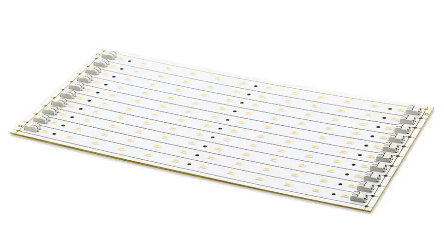
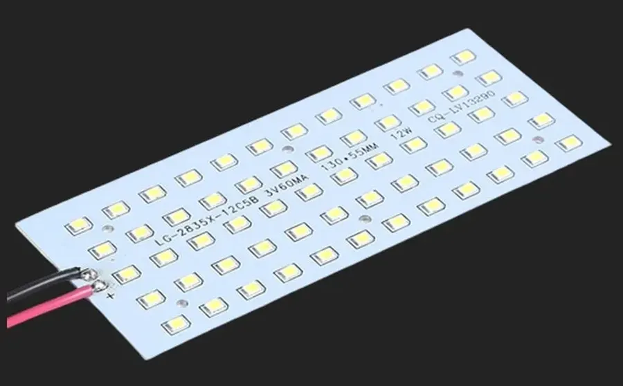
| Aluminum PCB | Features a metal core, typically aluminum, for enhanced heat dissipation. | Excellent thermal conductivity, suitable for high-power LEDs, mechanically robust. | More expensive than FR-4 PCBs, heavier than standard PCBs. | High-power LED lighting, automotive LED lighting, industrial lighting |
Key Materials Used in LED PCB Board Manufacturing
The selection of materials in LED PCB manufacturing is pivotal, directly influencing thermal management, durability, and overall performance. This section will delve into the properties and applications of common materials such as aluminum, FR-4, and ceramic substrates, highlighting how each contributes to the efficacy and longevity of LED lighting systems.
| Material | Description | Thermal Conductivity | Typical Applications | Advantages | Disadvantages |
|---|---|---|---|---|---|
| Aluminum | A metal core PCB material commonly used for its excellent thermal dissipation. | High (approx. 237 W/m·K) | High-power LEDs, Automotive lighting, Industrial lighting | Superior thermal management, Lightweight, Cost-effective for high power applications. | Electrically conductive (requires insulation), Heavier than FR-4. |
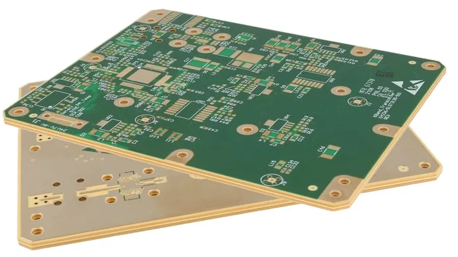
| FR-4 | A composite material made of woven fiberglass cloth with an epoxy resin binder. | Low (approx. 0.3 W/m·K) | Low to medium-power LEDs, General lighting, Control circuitry. | Cost-effective, Good electrical insulation, Easy to manufacture. | Poor thermal conductivity, Limited to low power applications. |
| Ceramic | Material characterized by its high thermal resistance, dimensional stability, and resistance to high temperatures. | High (varies greatly depending on the type of ceramic, but generally very high) | High-density LED arrays, High-power and high-temperature applications, High-reliability LED lighting. | Excellent thermal and electrical insulation, Superior thermal stability, Resistant to chemicals and corrosion. | Higher cost, Less impact resistant, More difficult to manufacture. |
| Copper | Used for traces and thermal vias, as well as in Metal Core PCBs(MCPCBs) | High (approx. 400 W/m·K) | All types of LED PCBs, heat sinking | Excellent electrical and thermal conductivity, widely available | More expensive than FR-4 |
Design Considerations for Effective LED PCB Boards

Effective LED PCB design is critical for ensuring optimal performance, longevity, and reliability of LED lighting systems. It encompasses several key elements, primarily focusing on thermal management, component placement, and trace layout. These considerations, when properly addressed, minimize operational issues such as overheating and performance degradation, thus achieving efficient and stable operation.
Each aspect of the design process interacts in a way that affects the overall performance of the LED PCB board, therefore each must be fully considered for an effective design.
| Design Element | Description | Importance |
|---|---|---|
| Thermal Management | Refers to how heat generated by LEDs and other components is dissipated | Prevents overheating, extends the lifespan of the LEDs, maintains stable performance and reduces the risk of component failure. |
| Component Placement | The strategic arrangement of LEDs, driver circuits, and other components on the PCB | Affects heat distribution, electrical performance and optimizes the circuit to avoid signal interference. |
| Trace Layout | The design of the conductive paths that carry electrical signals and power across the PCB | Ensures minimal signal loss, proper power delivery, and reduces electromagnetic interference. |
A comprehensive approach to LED PCB design considers all these aspects synergistically to create a robust, high-performing lighting solution. Each area needs careful planning and detailed execution to achieve the desired outcomes.
Applications of LED PCB Boards Across Industries
LED PCB boards, due to their energy efficiency, longevity, and compact design, have permeated a vast array of industries. Their versatility allows for deployment in applications ranging from simple indicators to complex lighting solutions, impacting both consumer and industrial sectors significantly. The adaptability of LED technology, combined with the robust nature of PCB construction, makes them an ideal choice for a multitude of applications.
- Residential Lighting
LED PCB boards are fundamental in modern residential lighting, powering everything from energy-efficient light bulbs and fixtures to smart home lighting systems. The move towards LED in homes is driven by their cost-effectiveness and long life span compared to traditional lighting. - Automotive Industry
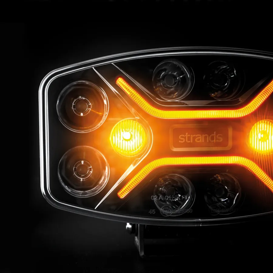
LED PCB boards are crucial for vehicle lighting, including headlights, taillights, interior lighting, and dashboard displays. Their durability and reliability are essential for the automotive environment. The design and placement of LEDs on PCBs also contribute to specific styling and safety requirements in vehicles. - Signage and Displays
The signage industry utilizes LED PCB boards for both indoor and outdoor displays. From large billboards to small retail signs, LED technology enables vibrant, energy-efficient displays that are easily customizable. Their high brightness and energy efficiency make them suitable for use in various advertising and information signage applications. - Consumer Electronics
LEDs on PCBs are integral to numerous consumer electronics such as smartphones, tablets, and televisions, serving as backlights, indicator lights, and flashlights. The compact size and low power consumption of LEDs make them ideal for integration into small portable devices. - Medical Devices
LED PCB boards are used in various medical devices, including diagnostic equipment, surgical lighting, and patient monitoring systems. The accuracy and reliability of LED lighting are critical in these applications, where precision and safety are paramount. Also, their low heat output is important for temperature sensitive equipment. - Industrial Applications
Industrial settings use LED PCBs in control panels, machine lighting, and safety equipment. The robust nature of LED PCB boards make them suitable for harsh industrial environments, offering dependable lighting and signaling capabilities. High brightness and durability are key features required in industrial applications. - Aerospace
LED PCBs are used for cockpit lighting, cabin lighting, and exterior navigation lights in aircraft. Their durability and high reliability are crucial in this demanding sector. The lightweight and efficient nature of LEDs contribute to energy saving and weight reduction within the aerospace industry.
Mounting LEDs on PCBs: Best Practices
The method of mounting LEDs onto a Printed Circuit Board (PCB) is crucial for both the electrical functionality and thermal performance of the final product. Selecting an appropriate mounting technique is vital for achieving optimal performance and long-term reliability in LED lighting applications. This section details the primary methods: surface mount technology (SMT) and through-hole technology (THT), emphasizing best practices.
- Surface Mount Technology (SMT)
SMT involves mounting LED components directly onto the surface of the PCB. This is the dominant technique for modern LED assembly due to its suitability for high-volume, automated manufacturing. LEDs are adhered to the board using solder paste, followed by reflow soldering. SMT components are generally smaller, leading to compact designs. This approach is ideal for applications needing precise placement and high density component arrangements. Key advantages include scalability and cost-effectiveness for large production runs. However, SMT components may be more susceptible to thermal stress if not handled correctly. Proper thermal design of the PCB and reflow profile optimization are crucial to avoid damaging components. - Through-Hole Technology (THT)
THT involves mounting LEDs with leads that pass through holes drilled in the PCB. After inserting the leads, the solder is applied on the opposite side of the board to secure the component. While less common in modern LED assembly, THT can still be relevant for larger or non-standard LED packages, situations requiring a more robust mechanical connection or for prototype work. THT is typically more labor intensive than SMT, making it less efficient for large-scale manufacturing. However, it generally offers enhanced mechanical stability and resistance to physical stress. This makes THT a suitable option in applications where the PCB will be subjected to more strain.
Regardless of the mounting method, several best practices should be observed to ensure reliable LED mounting.
- Pad Design and Layout
Ensure the pad layout on the PCB matches the LED component's specifications. The design must comply with IPC standards and include sufficient solderable areas for proper bonding and to facilitate heat dissipation. Correct pad design prevents soldering issues like tombstoning or cold joints. - Solder Paste Application
Use the correct type and quantity of solder paste for SMT. The volume and distribution of solder paste is critical to ensure good solder joints, thus preventing issues such as bridging and open connections. Applying solder paste requires precision, often done through stencil printing to ensure consistency and even distribution. - Reflow Soldering Profile
Optimize the reflow soldering profile to suit the components and solder paste being used. Pre-heating, peak temperature, and cooling rates must be carefully controlled to prevent thermal stress on the LEDs, as this can lead to premature failures. Temperature control is necessary to ensure the proper bonding of the solder and to avoid damaging LEDs. - Component Handling
Handle LED components carefully to avoid mechanical damage or contamination. Electrostatic discharge (ESD) precautions should be taken to protect LEDs from electrostatic shock, particularly in sensitive LED packages. Use proper ESD safe equipment when handling, especially in a manufacturing or research environment. - Inspection
Inspect soldered joints visually and, when needed, use X-ray to ensure proper solder joints. This is critical to check for solder joint quality, shorts, opens, and other defects. An effective inspection process is essential to catch issues early, preventing field failures.
LED PCB Board Design Considerations
Designing an effective LED PCB board requires careful consideration of several key aspects to ensure optimal performance, longevity, and reliability. These considerations encompass trace layout, thermal management via thermal vias, and proper pad design. Ignoring these elements can result in decreased efficiency and premature failure of the LED system.
- Trace Layout:
The copper traces on the PCB act as conductors, carrying power and signals to the LEDs. The width and spacing of these traces must be carefully calculated to handle the required current and minimize resistance, voltage drops, and heat generation. Poor trace design can lead to uneven current distribution, causing some LEDs to be brighter than others, and potentially damaging the circuit due to excessive heat. - Thermal Vias:
LEDs generate heat during operation, and this heat must be efficiently dissipated to prevent the LEDs from overheating and degrading. Thermal vias are small plated through-holes placed strategically around the LED components to facilitate heat transfer from the LED junction through the PCB and to a heat sink or other cooling system. The number and placement of thermal vias are critical, especially for high-power LEDs. Improper thermal management is a major contributor to reduced performance and shorter lifespan of LED systems. - Pad Design:
The pads on the PCB are the areas where the LED components are soldered. They must be carefully designed to ensure a reliable and robust electrical and mechanical connection. Sufficient pad size is crucial for proper soldering and heat transfer. Inadequate pad design can lead to poor solder joints, and unreliable connectivity, and can also hinder heat dissipation.
Optimal heat dissipation is paramount for LED PCB design. Heat is the primary factor affecting the performance and longevity of LED systems. Efficient heat dissipation is achieved through a combination of optimized thermal vias, PCB material selection (e.g., using aluminum PCBs for better thermal conductivity), and external heat sinks, if necessary. Neglecting heat management is a leading cause of premature LED failure.
| Design Aspect | Importance | Best Practices |
|---|---|---|
| Trace Layout | Ensures efficient current flow, minimizes voltage drops, and prevents overheating. | Use appropriate trace width and spacing based on the required current; consider using power and ground planes for better heat dissipation. |
| Thermal Vias | Facilitate heat transfer away from the LED junction, preventing overheating. | Strategically place thermal vias close to the LED pads; use a sufficient number of vias based on thermal load. |
| Pad Design | Ensures reliable electrical and mechanical connections and good heat transfer. | Use adequately sized pads for proper soldering and heat dissipation; consider using thermal pads. |
Frequently Asked Questions About LED PCB Boards
This section addresses frequently asked questions about LED PCB boards, providing concise, authoritative answers to common queries regarding their design, materials, applications, and sourcing. These answers are grounded in fundamental principles of electronics and manufacturing, offering clear insights for both beginners and experienced users.
- What are the primary advantages of using Aluminum PCB for LEDs?
Aluminum PCBs offer superior thermal conductivity compared to FR-4, enabling efficient heat dissipation from LEDs. This reduces operating temperatures, enhances LED lifespan, and improves overall system reliability. Aluminum substrates also provide mechanical strength and durability. - How do I choose the correct material for my LED PCB design?
The choice of material depends on factors like thermal performance requirements, mechanical stress, operating environment, and cost. Aluminum is ideal for high-power LEDs demanding efficient heat dissipation. FR-4 is a cost-effective option for less demanding applications. Other materials like copper or ceramics might be chosen for specific needs. Consider your application's requirements and consult material datasheets for specific properties. - What are the steps involved in designing a custom LED circuit board?
Designing a custom LED PCB involves specifying the circuit, choosing suitable components, creating a layout that manages heat and electrical performance, generating Gerber files, and choosing a reliable manufacturer. Start with a schematic, determine your thermal management strategy, use PCB design software to develop a layout, and consider best practices in component placement and trace routing. - Where can I source high-quality LED circuit boards?
High-quality LED PCBs can be sourced from reputable manufacturers that specialize in PCB fabrication. Look for manufacturers with ISO certifications, strict quality control processes, and experience in LED board production. Verify their capabilities regarding materials, tolerances, and surface finishes. Consider also, the delivery time and the manufacturer's pricing structure. - Can you explain the difference between single-layer and multi-layer LED PCBs?
Single-layer PCBs have conductive traces on one side of the substrate, offering a simple, cost-effective solution for basic LED applications. Multi-layer PCBs have conductive traces on multiple layers within the substrate. These boards offer greater design flexibility and allow for more complex circuits, better thermal management, and higher component density. - How does thermal management impact the performance of LED PCBs?
Effective thermal management is critical for optimal performance and longevity of LED PCBs. Excessive heat can lead to reduced luminous output, color shift, and premature failure of LEDs. Employing appropriate PCB materials, thermal vias, heat sinks, and careful component placement are crucial strategies for managing heat effectively. - What are the typical trace layout considerations for LED PCBs?
Trace layout on LED PCBs should minimize resistance and ensure adequate current-carrying capacity for each LED. Wider traces are often required for high-power LEDs. Consider impedance matching, especially in high frequency applications. Employing techniques such as star routing can improve the balance of current and voltage across multiple LEDs. Avoid sharp corners in the traces, and always ensure adequate isolation between traces to prevent shorts.
LED PCB boards are at the heart of modern lighting technology, and their continued innovation will continue to illuminate our lives. From their sophisticated designs to their versatile applications, understanding LED PCB boards is essential for anyone involved in electronics, lighting, or product design. As technology evolves, so will these crucial components, powering a brighter future for all.