Mastering Circuit Board Soldering: A Comprehensive Guide
Circuit board soldering, a fundamental skill in electronics, is akin to building with tiny, precise components. It’s the process of joining these components to create functioning circuits, much like laying bricks in construction, but on a microscopic scale. This guide will illuminate the path to mastering this essential technique, ensuring reliable connections and bringing your electronic projects to life, from the basics to advanced tips.
Understanding the Basics of Circuit Board Soldering
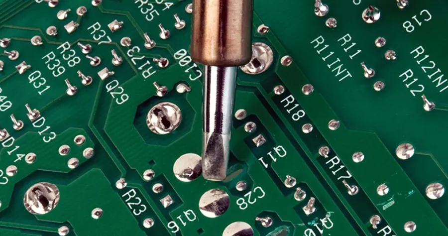
Circuit board soldering is a fundamental process in electronics assembly, involving the use of a molten metal alloy (solder) to create a permanent electrical connection between electronic components and the conductive pads on a printed circuit board (PCB). This process ensures both mechanical and electrical integrity, crucial for the proper functioning of any electronic device. Solder, typically a tin-lead or tin-silver alloy, acts as a conductive 'glue,' while flux is used to clean the metal surfaces and promote better solder flow. There are two primary methods of soldering: through-hole and surface mount, each requiring different techniques and tools.
| Feature | Through-Hole Soldering | Surface Mount Soldering |
|---|---|---|
| Component Mounting | Components have leads inserted through holes in the PCB. | Components are placed directly on the surface of the PCB. |
| Solder Application | Solder is typically applied to the leads on the opposite side of the board. | Solder paste is often used and melted with hot air or reflow oven. |
| Tooling | Requires basic soldering iron and manual dexterity. | Requires specialized equipment like hot air stations and fine-tipped irons. |
| Complexity | Generally easier for beginners due to larger component size. | More complex and requires precision due to the size and close spacing of components. |
| Use Cases | Suitable for prototyping and simpler circuit designs. | Essential for high-density, compact, and automated assemblies. |
Essential Tools for Circuit Board Soldering
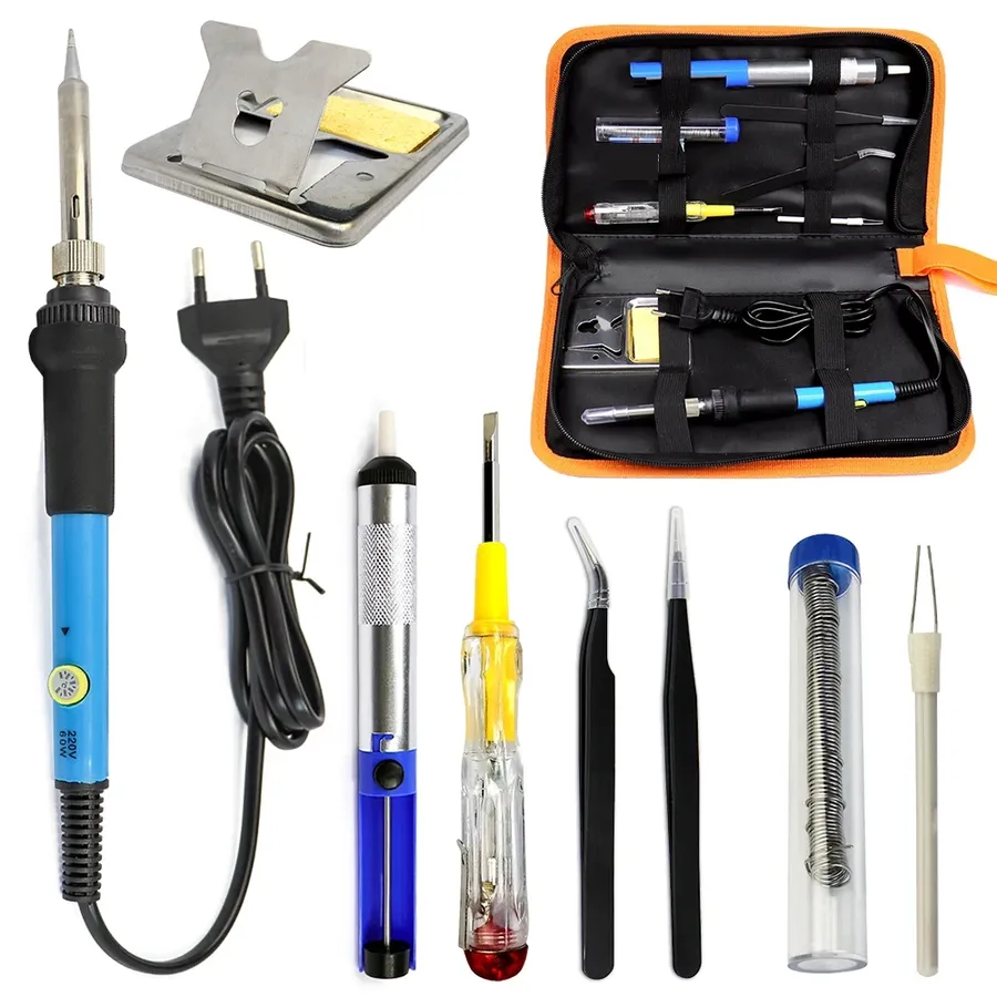
Achieving reliable solder joints on circuit boards requires a specific set of tools, each playing a crucial role in the process. This section details the essential equipment, focusing on their function, types, and key considerations for selection to ensure effective and safe soldering practices.
| Tool | Description | Types/Considerations |
|---|---|---|
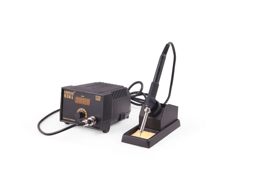
| Soldering Iron | Provides heat to melt solder and form a joint. | Variable wattage (15W-60W typical), temperature controlled, various tip shapes (conical, chisel, fine-point) |
| Solder Wire | Metal alloy that melts to form the conductive bond. | Lead-based (e.g. 60/40 tin-lead) or lead-free (e.g. SAC305), various diameters (0.5mm - 1.0mm), with/without flux core |
| Flux | Chemical agent that cleans surfaces and improves solder flow. | Rosin-based (most common), no-clean, water-soluble; available in liquid, paste, or pen form |
| Desoldering Tools | Removes solder from joints to correct errors or replace components | Solder sucker (manual or electric), desoldering wick (braided copper wire) |
| Safety Gear | Protects user from burns, fumes, and other hazards. | Safety glasses or goggles, fume extractor, heat-resistant gloves, appropriate clothing |
Preparing Your Workspace and Materials for Circuit Board Soldering
A well-prepared workspace is crucial for successful and safe circuit board soldering. This involves ensuring proper ventilation, organizing components for easy access, and meticulously cleaning both the PCB and its components prior to soldering. These steps minimize the risk of errors, prevent the introduction of contaminants, and contribute to the overall quality of the soldered connections.
- Ventilation
Ensure adequate ventilation in your workspace to remove soldering fumes, which can be harmful. This can be achieved by working near an open window or using a fume extractor fan. Proper ventilation is essential to avoid respiratory irritation and long-term health issues associated with soldering fumes, which are typically composed of rosin and lead particles. Studies by OSHA confirm that extended exposure can lead to various health problems and that sufficient extraction measures must be in place. - Workspace Organization
Organize your components, tools, and solder on a clean, well-lit work surface. Using component trays or organizers can prevent clutter and loss of components, which saves time and reduces the risk of damage from handling. Keeping your work area clutter-free is directly proportional to the efficiency and quality of the soldering process. - PCB Cleaning
Clean the printed circuit board using isopropyl alcohol (IPA) and a lint-free cloth or brush to remove dust, oils, and other contaminants. A clean PCB ensures proper solder adhesion, preventing the formation of poor solder joints. Contaminants can lead to non-wetting and non-conductive joints. The surface tension of the solder can also be altered by the presence of these contaminants, causing unpredictable results. - Component Cleaning
Clean component leads using a soft brush or IPA to remove any oxidation or contaminants. This step is essential for ensuring a strong and reliable solder joint because solder only bonds to clean metal surfaces. Oxidation can act as a barrier to solder flow, hence the importance of ensuring clean leads prior to soldering. - ESD Protection
Use an anti-static mat and a wrist strap to prevent electrostatic discharge (ESD) which can damage sensitive electronic components, particularly CMOS circuits. ESD is a significant hazard to electronic components, especially in dry environments, and proper precautions are crucial to prevent component failures.
Step-by-Step Guide to Through-Hole Soldering
Through-hole soldering is a fundamental skill in electronics assembly, involving the secure attachment of components with leads that pass through holes in a printed circuit board (PCB). This process, while seemingly straightforward, requires a careful approach to ensure reliable electrical connections and prevent damage to components. Mastering through-hole soldering is crucial for both beginners and seasoned professionals as it forms the basis for more advanced techniques.
- Component Insertion
Begin by carefully inserting the component leads into their corresponding holes on the PCB. Ensure the component sits flush against the board surface (or is positioned correctly if it has standoffs or specific mounting requirements). If necessary, lightly bend the leads on the back of the board to secure the component in place, preventing it from falling out during the soldering process. Take care to avoid any bending stress on the component body. - Heating the Joint
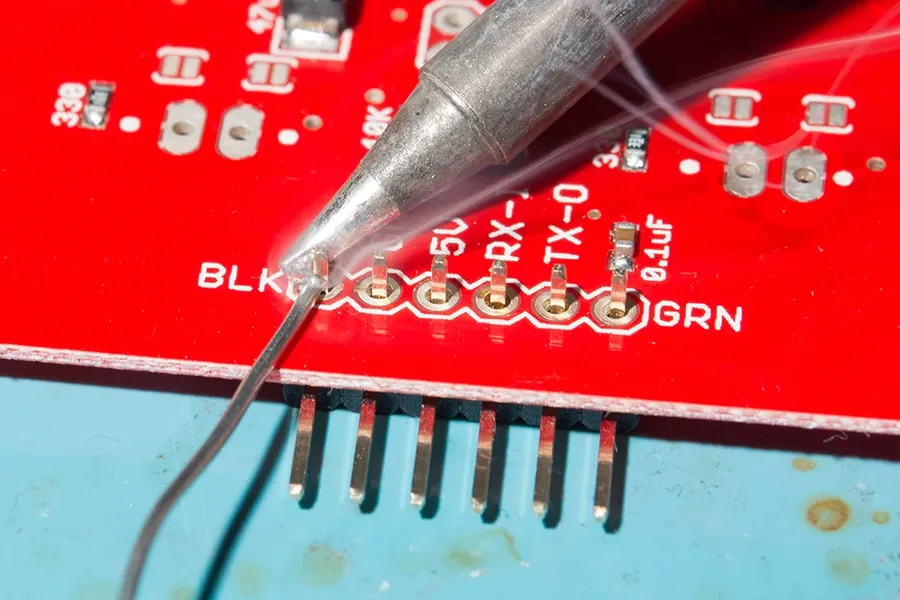
Position the soldering iron tip so that it simultaneously contacts both the component lead and the pad on the PCB. Apply heat to both surfaces for a few seconds, allowing them to reach the solder's melting temperature. The duration of heating depends on the size of the pad and lead, as well as the soldering iron's wattage. It’s essential to avoid excessive heating which can damage the component or PCB pad. - Applying Solder
Once the joint is heated sufficiently, apply solder to the junction of the heated lead and the pad. The solder should melt and flow smoothly around both parts of the joint forming a small fillet. Feed solder until a sufficient amount has been applied, then remove the solder wire and, then the soldering iron. The goal is to create a smooth, shiny solder joint that provides a solid mechanical and electrical connection. Avoid using too much solder, which can create bridges to adjacent pads or leads. - Allowing the Joint to Cool
Allow the solder joint to cool and solidify naturally after you remove the iron. It is vital to avoid any movement or vibration during the cooling process as this may result in a ‘cold’ or brittle solder joint. - Inspection
Once cooled, visually inspect the solder joint. A good solder joint should be smooth, shiny, and concave, forming a ‘volcano’ shape around the component lead, making a strong mechanical and reliable electrical connection.
Achieving optimal temperature control during soldering is critical. Too low a temperature results in a cold solder joint, which is characterized by a dull, grainy appearance and a weak connection. Conversely, excessive heat can damage the PCB and component. A temperature range of 315°C to 370°C (600°F to 700°F) is generally suitable for lead-based solder, with slightly lower temperatures recommended for lead-free solder, but should be confirmed by the solder manufacturer's specific instructions. Practice and careful observation are key to developing a feel for the correct heating time and solder application.
Surface Mount Soldering Techniques

Surface mount soldering is a technique for attaching electronic components directly onto the surface of a printed circuit board (PCB). Unlike through-hole soldering, which involves inserting component leads through holes in the board, surface mount technology (SMT) components are soldered to pads on the PCB surface, allowing for higher component density and smaller device sizes.
The process of surface mount soldering involves precise placement of components and careful application of heat and solder, often employing specialized tools and techniques. The small size of SMT components requires a high level of precision and attention to detail during the soldering process. Common techniques include using solder paste, hot air tools, and fine-tipped soldering irons, each offering a way to heat the solder and achieve solid joints.
- Solder Paste Application
Solder paste, a mixture of solder particles and flux, is applied to the PCB pads using stencils or manual application methods. The amount and distribution of solder paste are critical for reliable solder joints. - Component Placement
SMT components are then carefully placed onto the solder paste, typically using tweezers or a vacuum pick-up tool. Accuracy is paramount to align component leads to the pads. - Reflow Soldering
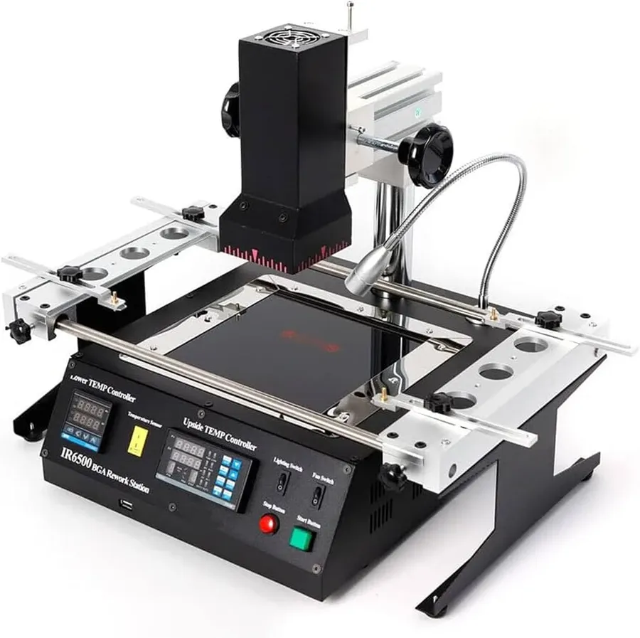
Heat is applied to the solder paste to melt the solder and form solder joints, which is usually achieved with hot air rework stations, reflow ovens, or even specialized soldering irons. Precise temperature control is essential to avoid damaging components or the PCB. The solder paste melts, the solder makes contact with the component terminals and PCB pads, forming a permanent electrical connection. - Inspection
After soldering, the solder joints are inspected for quality and proper connection, and any defects need to be repaired to ensure the reliability of the assembled circuit board.
| Technique | Description | Advantages | Disadvantages |
|---|---|---|---|
| Hot Air Rework Station | Uses a focused stream of hot air to melt solder. | Good for reflowing multiple components simultaneously, adjustable temperature and airflow, versatile for various components. | May require more practice and precision, can displace small components if airflow is too strong, can cause overheating if not controlled correctly. |
| Fine-Tipped Soldering Iron | A soldering iron with a very fine tip is used to melt solder. | Precise control, best for single component soldering, cost-effective. | Slower than hot air, less suitable for multiple pins or large surface mount components, can cause uneven heating. |
| Reflow Oven | A specialized oven to heat the entire PCB in a controlled manner | Uniform heating, suitable for mass production, efficient for complex boards. | Expensive, requires more setup, not suitable for single board repairs. |
When working with surface mount components, it's essential to use proper tools and techniques, focusing on consistent application of heat, solder, and flux to obtain reliable solder joints. Troubleshooting may include dealing with issues such as solder bridges, insufficient solder, or misaligned components, all of which require attention to detail and a solid understanding of the soldering process. With careful planning, proper equipment, and a little practice, the quality and reliability of surface mount soldering can be significantly improved.
Frequently Asked Questions About Circuit Board Soldering
Soldering circuit boards can present a variety of questions for both beginners and experienced users. This section addresses common queries regarding materials, techniques, and best practices to ensure successful and reliable solder joints.
- What type of solder is best for circuit boards?
The most common and recommended type of solder for circuit boards is a lead-tin alloy with a rosin core. A 60/40 (60% tin, 40% lead) or a 63/37 alloy is often preferred for its lower melting point and good wetting properties. Lead-free solders are also widely used, particularly in commercial applications, for environmental considerations. Common lead-free alloys include tin-silver-copper (SAC) mixtures. The choice often depends on environmental regulations, user preference and application. - Is flux necessary when soldering circuit boards?
Yes, flux is essential for effective soldering. It acts as a cleaning agent, removing oxidation from the metal surfaces to be joined. This promotes proper solder flow and creates a reliable bond. Rosin-based flux is commonly used in electronics soldering. Flux is typically present in cored solder wire but sometimes additional flux is required, such as a liquid or gel form. - What is the optimal soldering temperature for circuit boards?
The ideal soldering temperature for circuit boards depends on the solder alloy. For lead-based solder, a temperature of 350-370°C (662-698°F) is usually adequate. Lead-free solders often require a slightly higher temperature, around 370-400°C (698-752°F). It is important to avoid overheating, which can damage components, or using too low of a temperature, which can result in a cold solder joint. Always refer to the solder manufacturer’s recommendations. - How do you fix solder bridges on a circuit board?
Solder bridges, or solder shorts, occur when solder unintentionally connects two or more adjacent pads. To fix them, first use a clean soldering iron to reheat the bridge and remove excess solder with desoldering wick. Another option is to use a solder sucker to remove the excess solder. Ensure that no two pads are connected after the repair. - Can I use a regular soldering iron for circuit board soldering?
While a basic soldering iron can be used, a temperature-controlled soldering iron with a fine tip is strongly recommended for circuit board work. This type allows for more precise heating control, and a fine tip allows for work on smaller components. This helps prevent damage from excessive heat and provides more accurate solder placement, especially for surface mount components. - How do I clean a PCB after soldering?
After soldering, residue from flux can leave a sticky film that may corrode over time or cause electrical problems. Use isopropyl alcohol (IPA) with a small, soft brush to remove the residue. Be sure to allow the PCB to completely dry after cleaning.
Common Circuit Board Soldering Problems and Troubleshooting
Effective circuit board soldering is crucial for reliable electronic devices; however, several common issues can arise. These problems, if not addressed properly, can lead to circuit malfunctions or device failure. This section delves into identifying, resolving, and preventing common soldering problems, ensuring robust connections and overall circuit integrity.
| Problem | Description | Causes | Solutions |
|---|---|---|---|
| Cold Solder Joint | A weak or unreliable joint characterized by a dull, grainy appearance. | Insufficient heat, movement during cooling, or contaminated surfaces. | Reheat the joint with adequate heat and ensure stability during cooling. Clean surfaces with isopropyl alcohol and apply flux. |
| Solder Bridges | Unintended connections formed between adjacent solder joints. | Excessive solder, inappropriate tip size, or misalignment of components. | Use solder wick or a desoldering pump to remove excess solder. Adjust tip size and accurately position the components. |
| Lifted Pads | Detachment of the conductive pad from the PCB substrate. | Excessive heat, mechanical stress during soldering or desoldering, or faulty PCB materials. | Carefully apply heat and lift the pad back into place (use solder mask if required). Exercise caution to minimize stress when soldering. |
| Burnt Components | Component damage from prolonged or excessive heat exposure. | Excessive soldering temperature, prolonged exposure to heat, or incorrect tip size. | Use the correct soldering temperature, apply heat for the shortest necessary period, and use a tip size appropriate for the component. |
Preventative measures, such as proper temperature calibration, using appropriate tools, and maintaining a clean working environment, are key to avoiding these issues. Regular checks of equipment and materials also contribute to consistent, high-quality soldering results. Understanding these common problems and their solutions is vital for anyone involved in PCB assembly or repair.
Advanced Soldering Tips and Techniques
Mastering circuit board soldering involves more than just basic techniques. This section explores advanced methods that enhance soldering efficiency and reliability, focusing on precision and problem-solving in complex scenarios. These techniques are essential for professionals and serious hobbyists aiming for high-quality, durable solder joints. We will delve into the use of specialized tools and approaches for optimal results.
- Solder Wick Usage
Solder wick, also known as desoldering braid, is a copper braid used to remove excess solder. It's crucial for correcting mistakes like solder bridges or removing components for rework. To use it effectively, place the wick over the unwanted solder and apply heat with the soldering iron. The solder will be drawn into the braid due to capillary action. - Rework Stations
Rework stations provide controlled heat and airflow for safely removing and replacing surface mount components. They often include hot air guns and preheating plates, which are vital for dealing with intricate boards and temperature-sensitive components. A controlled environment is essential to prevent damaging the board or other nearby components when resoldering or removing a component. - Specialized Soldering Tips
Different soldering tips are designed for specific applications. Fine-point tips are ideal for precision surface mount work, while chisel tips are better for through-hole components and larger solder joints. The size and shape of the tip directly impacts heat transfer, solder flow, and overall efficiency. Choosing the right tip ensures optimal contact and precision. - Reflow Soldering
While reflow soldering is commonly used in mass production, it can also be employed for intricate jobs. This process involves applying solder paste to pads, placing the components, and heating the entire board in a controlled manner until the solder melts (reflows) to form solder joints. It's advantageous for handling dense, multi-pin surface mount components. When applying it to custom projects, proper preparation and a controlled reflow method are key.
| Technique | Description | Application | Key Benefit |
|---|---|---|---|
| Solder Wick | Braided copper wire used to remove excess solder. | Correcting solder bridges, removing components. | Precise solder removal |
| Rework Station | Device with controlled heat and airflow | Removing and replacing surface mount components. | Controlled and safe component removal |
| Specialized Tips | Various shapes and sizes for specific tasks. | Different joints and component sizes | Optimized heat transfer |
| Reflow Soldering | Heating the entire board with solder paste | Dense surface mount components | Simultaneous soldering |
Safety Precautions When Soldering Circuit Boards
Soldering circuit boards involves working with high temperatures and potentially hazardous materials. Adhering to strict safety protocols is crucial to prevent injuries and ensure a safe working environment. This section provides essential guidelines for minimizing risks associated with soldering.
- Ventilation
Adequate ventilation is paramount. Soldering produces fumes from both the solder and flux, which can be harmful if inhaled. Work in a well-ventilated area, preferably using a fume extractor to draw away these harmful fumes. Ensure proper air circulation to prevent the build-up of fumes in your workspace. - Eye Protection
Always wear safety glasses or goggles to protect your eyes from solder splatter or flying debris. The intense heat of soldering can cause molten solder to eject unexpectedly. This is particularly important if working with lead-based solder. - Skin Protection
Wear gloves, preferably heat-resistant ones, to prevent burns. Long sleeves and pants are also recommended to protect your skin from hot components and solder. Avoid wearing jewelry that might conduct heat or get caught in equipment. - Hand Washing
Wash your hands thoroughly with soap and water after soldering, especially before eating or touching your face. This will help remove any lead or other potentially toxic substances that may be present on your skin. Using hand sanitizer is not an adequate substitute to properly washing your hands. - Fire Safety
Keep a fire extinguisher rated for electrical fires close by. Soldering equipment can malfunction, and hot components can ignite flammable materials. Never leave a soldering iron unattended while it's powered on. - Handling Solder and Flux
Solder containing lead is hazardous if ingested. Avoid touching your mouth or face when handling solder. Flux can also cause skin and eye irritation, be sure to wear gloves and eye protection to avoid any chemical burns. Ensure that all materials are handled with care and that any spillages are cleaned up promptly. - Proper Disposal of Materials
Dispose of used solder, flux, and any other waste materials in accordance with local regulations. Do not dispose of these items in general waste or down the drain. Lead-containing materials require special disposal methods.
Mastering circuit board soldering is more than just connecting components; it's about creating robust, functional electronics. This guide has covered essential techniques, from selecting the right soldering tools and materials to troubleshooting common issues and adopting best safety practices. Through practice and attention to detail, you can transform your soldering skills from a basic necessity into an art form, paving the way for countless innovative projects. Remember, precise soldering ensures your circuit boards function as intended, just like laying the perfect foundation for a skyscraper, one careful join at a time.