Mastering Stripboard: A Comprehensive Guide for Electronics Prototyping
In the realm of electronics, where innovation sparks from experimentation, [stripboard], also known as Veroboard, stands as a cornerstone for prototyping. It's the unsung hero that bridges the gap between ideas and tangible circuits, allowing enthusiasts and professionals alike to quickly test and refine their designs. This guide delves deep into the world of stripboard, unraveling its intricacies and equipping you with the knowledge to confidently navigate your prototyping endeavors. From understanding its structure to mastering practical techniques, prepare to unlock the full potential of stripboard in your projects.
Understanding Stripboard Basics
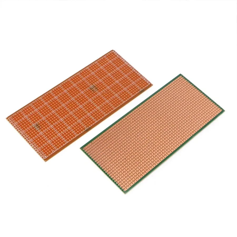
Stripboard, also known as Veroboard, is a fundamental prototyping material in electronics, characterized by its pre-drilled holes arranged in a grid pattern, interconnected by parallel strips of copper on one side. This structure facilitates the easy construction of electronic circuits without the need for custom printed circuit boards (PCBs), allowing for rapid testing and development of electronic designs.
The standard hole spacing on stripboard is typically 0.1 inches (2.54 mm), a crucial dimension because it is compatible with most through-hole electronic components, integrated circuits (ICs), and connectors. This standardization allows for easy placement and soldering of components directly onto the board. Different stripboard types may vary in size and overall dimensions but will nearly always follow this grid spacing.
Several types of stripboard exist, varying primarily in the material of the base substrate, copper thickness, and the presence of additional features such as solder masks. Variations include single-sided boards (with copper tracks on one side) and double-sided boards, which allow for more complex and compact layouts.
Stripboard vs. Perfboard vs. Breadboard: A Detailed Comparison

When embarking on electronics prototyping, choosing the right platform is crucial. Stripboard, perfboard, and breadboard each serve distinct purposes, offering unique advantages and disadvantages. This section provides a comparative analysis to guide your selection based on your project needs.
| Feature | Stripboard | Perfboard | Breadboard |
|---|---|---|---|
| Structure | Pre-etched copper strips | Grid of isolated holes | Interconnected spring clips |
| Connectivity | Components connected via copper strips, cuts required | Requires point-to-point wiring | Components plugged into interlinked connection points |
| Ease of Use | Moderate - requires track cutting and soldering | Moderate - requires wiring and soldering | High - solderless, plug-and-play |
| Durability | High - permanent once soldered | High - permanent once soldered | Low - not suitable for permanent projects |
| Component Suitability | Ideal for through-hole components, requires pre-planning for layouts | Flexible for various components, layout flexibility | Primarily through-hole components, limitations in component size |
| Project Suitability | Small to medium-sized, permanent prototypes | Medium-sized, permanent prototypes, more versatile layout | Temporary prototyping, learning circuits, easy iterative design |
| Cost | Low | Low | Moderate |
| Reusability | Low - generally not reusable once project is complete | Low - generally not reusable once project is complete | High - components can be easily reused |
Essential Tools and Equipment for Stripboard Projects
Successfully constructing projects on stripboard requires a set of specialized tools that enable precise component placement, secure soldering, and accurate circuit modifications. These tools are not merely conveniences, but rather integral to ensuring the reliability and functionality of your electronic circuits built on stripboard.
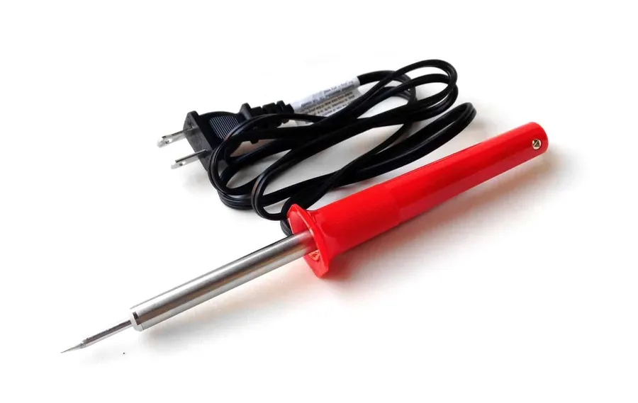
- Soldering Iron
A temperature-controlled soldering iron with a fine tip is essential for creating reliable solder joints without damaging components or the stripboard. Consider a station with adjustable temperature settings to accommodate various solder types and component sizes. - Solder
Use rosin-core solder with a diameter suitable for electronics work (typically 0.7-1mm). Lead-free solder is more environmentally friendly but may require a slightly higher soldering temperature. - Wire Strippers
Quality wire strippers with different gauge settings ensure that wire insulation is removed neatly and without damaging the conductors. Precise wire stripping is crucial for reliable connections. - Cutting Tools
A sharp pair of side cutters or flush cutters are necessary for cleanly cutting component leads and wires. A stripboard cutter or a craft knife is also essential for creating breaks in copper tracks or for separating sections of the board. - Desoldering Tools
Desoldering pumps or desoldering braid are important for removing components if corrections or modifications are required. These tools help to avoid damage to components or the board when rework is needed. - Multimeter
A digital multimeter is indispensable for testing circuits, measuring voltages, currents, and resistances. It is key for verifying continuity, detecting short circuits, and debugging designs,ensuring the functionality of the project. - Helping Hands
A helping hands tool or similar is incredibly helpful for holding stripboard or components in place during soldering. This can significantly improve the precision and safety of your work. - Safety Glasses
Safety glasses are mandatory when soldering, cutting, or working with any tools, protecting the eyes from splatters or flying debris.
Investing in good quality tools will significantly improve the reliability and longevity of your stripboard projects, while also enhancing the overall building experience. Creating an organized and well-lit workspace will further increase your success rate and reduce frustration, with special attention paid to ensuring good ventilation and safety.
Step-by-Step Guide to Planning and Layout for Stripboard Circuits
Effective stripboard circuit layout begins with a meticulous planning phase, bridging the gap between a circuit diagram and its physical implementation. This involves interpreting the schematic, strategizing component placement, and understanding how to minimize errors to create a functional and reliable prototype.
- Interpreting the Schematic Diagram
Begin by thoroughly understanding the circuit diagram. Identify all components, their values, and their interconnections. Note the flow of current, especially if it is a more complex circuit, this understanding is vital for proper planning. - Mapping the Circuit to Stripboard
Translate the schematic into a stripboard layout. Represent each track as a conductive line on your layout, ensuring components are placed where they can be linked using the pre-existing copper tracks, while minimizing the need for jumpers or wire links. Start by positioning the most crucial components first, e.g. integrated circuits and power supply connections. - Component Placement and Orientation
Strategically position components to maximize track utilization and minimize the need for additional wiring. Consider component orientation to make it easier to connect them, always referencing the datasheet to avoid connection errors. This planning step also involves visualizing any required track breaks. - Planning Track Cuts
Identify where track cuts are necessary to isolate certain component terminals and avoid short circuits. Mark the required track cuts directly on the board for a clear visual guide during assembly. Track cuts must always be made perpendicular to the tracks and must not connect to other tracks in the process. - Double-Check Your Layout
Carefully review your planned stripboard layout to check for any misaligned connections or components that might need different wiring. Trace the signal paths to ensure they correctly reflect the original schematic, this helps catch common errors, such as incorrect pinout wiring and component connection errors. Make sure to verify any integrated circuit pinout connections to the specific chip that you intend to use. - Marking and Assembly
Before beginning to solder, verify that all markings are clear and accurate, make sure that all component positions, track breaks, and jumpers are clearly marked. This clarity is essential for a smooth and error-free assembly of your circuit. Then begin the assembly process by gently pressing the components into the board and cutting the legs with the cutting tool. Ensure that all components are flush to the stripboard.
By meticulously planning each step, from circuit diagram interpretation to final assembly, you can avoid many common stripboard errors and create a functional and reliable prototype. This method saves time and ensures that your finished project operates as expected.
Soldering Techniques and Best Practices for Stripboard
Effective soldering on stripboard is critical for establishing robust electrical connections and ensuring the longevity of your electronic projects. Proper technique minimizes the risk of dry joints, shorts, and component damage, leading to more reliable and efficient circuits.
This section provides a step-by-step guide to soldering components onto stripboard, focusing on best practices and addressing common pitfalls. It also includes guidance on efficient desoldering techniques.
- Preparation is Key
Before soldering, ensure your stripboard and components are clean. Use isopropyl alcohol to remove any contaminants. Tin the soldering iron tip and ensure the temperature is appropriate for the solder you are using (typically 300-350°C for leaded solder and 350-400°C for lead-free solder). Components should be prepared by pre-bending their leads to ensure easy and correct fitment onto the stripboard. - Step-by-step soldering guide
1. **Position Components:** Place the component on the stripboard, ensuring its leads are correctly aligned with the copper tracks and holes. 2. **Heat the Joint:** Apply the soldering iron tip to the junction of the component lead and the copper track. Heat both simultaneously for 2-3 seconds. Avoid excessive heat, which can lift the copper track. 3. **Apply Solder:** Feed solder onto the heated junction where the lead and track meet. Use only enough solder to create a smooth, shiny, concave joint. Do not apply solder to the tip of the iron and then transfer it to the joint; always bring the solder wire into contact with the hot joint itself. 4. **Remove Heat:** Remove the soldering iron promptly after the solder has flowed and created the joint. Do not move the component while the solder is still molten. 5. **Inspect the Joint:** Once the solder has cooled and solidified, visually inspect each joint for smoothness and a concave shape. A smooth, shiny joint is indicative of a good electrical connection. A dull or lumpy joint may indicate a dry joint that is prone to failure. - Best Practices for Specific Components
For through-hole components, ensure the leads are trimmed after soldering. For larger components like electrolytic capacitors, ensure correct polarity and secure them with a drop of glue to avoid stress on solder points. Surface-mount components can be used with the correct soldering techniques, using flux and a very fine soldering tip. It is always best practice to work on one joint at a time. - Dealing with Dry Joints
Dry joints occur when the solder does not properly adhere to the component lead or the stripboard, resulting in a poor electrical connection. Reheat the joint and apply a small amount of fresh solder with flux to resolve a dry joint. Always ensure the joint is properly cleaned and the surfaces to be soldered are free from contaminants. - Efficient Desoldering
If a component needs to be removed, a desoldering pump or solder wick can be used. Heat the solder joint with the soldering iron until the solder melts, and then quickly use the desoldering tool to remove the solder. Gently lift the component after removing all solder. Take care to avoid damaging the copper tracks on the stripboard.
Troubleshooting Common Stripboard Issues
Effective troubleshooting is crucial for successful stripboard projects. Common issues such as short circuits, dry joints, and trace breakages can impede functionality, and a systematic approach is essential for identifying and resolving them. Careful visual inspection coupled with logical testing will ensure project reliability.
- Short Circuits
Short circuits occur when unintended connections are made between different parts of the circuit, often due to solder bridges or misplaced components. To diagnose, visually inspect for solder bridges, particularly between adjacent tracks or component leads. Use a multimeter to check for continuity between points that should be isolated. To rectify, carefully remove excess solder with solder wick and ensure components are correctly placed and isolated. - Dry Joints
Dry joints are poor solder connections that have not properly adhered to the metal surface due to insufficient heat or movement during cooling, resulting in high resistance and intermittent connection. Visually they appear dull, granular, and not shiny. To diagnose, use a multimeter to test the resistance of connections that appear suspect, or wiggle suspect components to identify intermittent problems. To rectify, reflow the solder joint using adequate heat and flux, ensuring a shiny and smooth connection. - Trace Breakage
Trace breakages are interruptions in the conductive copper tracks. These can occur due to physical stress or damage, often when the copper is cut or scraped too aggressively. Visually, look for gaps or damage along the copper tracks, if they are not very obvious, use a continuity tester to locate any breaks and then use a wire jumper to bridge the broken connection. If the damage is excessive, replacement of the stripboard may be necessary. - Component Failure
Components themselves can fail or malfunction. Before assuming the problem lies with the stripboard, verify that components are functioning correctly. Check datasheets for appropriate specifications and test using a component tester or multimeter. - Incorrect Component Placement
Placing components in the wrong location or orientation can disrupt circuit functionality. Double-check component placement against the layout diagram. Ensure polarized components, such as electrolytic capacitors and diodes, are installed in the correct direction.
Testing is an integral part of the troubleshooting process. Use a multimeter to check for continuity, voltage, and current at various points in the circuit. Start by confirming power supply is present and working correctly. Then work your way through the design, checking critical connections.
Stripboard Layout Tips and Tricks for Efficient Design
Efficient stripboard layouts are crucial for creating reliable and compact electronic circuits. This section explores advanced techniques, focusing on optimizing space, minimizing errors, and enhancing the overall functionality of your stripboard projects by strategic component placement, the use of jumpers and wire links, and the adoption of best practices for efficient design.
- Strategic Component Placement
Prioritize the placement of critical components such as power supply elements, microcontrollers, and signal processing circuits first. Arrange components to minimize the number of track cuts and wire links required. Aim for a layout that logically flows from input to output, aiding in troubleshooting and circuit comprehension. - Utilizing Jumpers and Wire Links
Jumpers are essential for bridging gaps and connecting non-adjacent tracks. Use insulated wire jumpers to avoid short circuits. Employ dedicated jumper wires or pre-made jumper kits, which are often more secure than relying on component leads for bridging. Keep wire runs short and organized. - Minimizing Track Cuts
Carefully plan your layout to minimize the number of track cuts required, this reduces the potential for creating weak connections or accidental breaks. Each cut represents a potential point of failure, so efficient layout planning is key. Group related components to reduce the frequency of track breaks and simplify the circuit. - Planning for Component Size and Orientation
Take into account the physical size of all components, ensuring adequate spacing to avoid overlapping or crowding which can lead to short circuits or difficulties in accessing components during troubleshooting and assembly. Orient all polarized components (such as diodes and electrolytic capacitors) properly according to the schematic diagram. - Color-Coding for Organization
Use different colored wires for power, ground, and signal lines. This helps you to quickly identify and distinguish between different types of connections in complex circuits, reducing confusion and facilitating troubleshooting. Consistent color-coding is helpful to manage the complexity of larger circuits. - Documentation of your Layout
Maintain a detailed record of your stripboard layout for future reference or modifications. Note the location of all components, wire links, and track cuts. Clear documentation simplifies the debugging and further development stages. Consider taking photos or creating a diagram of your layout to ensure you can reference it if required.
Frequently Asked Questions About Stripboard
This section addresses common queries regarding stripboard, providing clear and concise answers to help users understand its applications, differences from other prototyping methods, and its nuances.
- What is a stripboard used for?
Stripboard is primarily used for creating semi-permanent electronic prototypes. It allows for the assembly of electronic circuits by soldering components to copper tracks, providing a robust alternative to breadboards when a more permanent solution is needed. It's ideal for small to medium scale projects that require more stability than a breadboard can offer but don't warrant a custom PCB. - What is the difference between a stripboard and a breadboard?
A breadboard is a solderless prototyping tool designed for temporary circuit construction. Components are pushed into the breadboard's holes and connected via internal conductive clips. This allows for easy experimentation and modifications. Conversely, a stripboard requires soldering components to copper tracks, creating a more permanent connection. Breadboards are advantageous for initial testing and prototyping, whereas stripboards are preferable when a more robust and stable prototype is required. - What is the difference between stripboard and perfboard?
Stripboard has continuous copper tracks running across its length, allowing components to be connected along these strips by soldering. Perfboard (also known as prototyping board or dot board) is a board with a grid of holes, without any pre-made tracks. Connections on perfboard are made point-to-point using wires, therefore offering more flexibility in component placement but potentially resulting in more wiring. Stripboard is quicker and easier for many basic circuits but is not as adaptable as perfboard for complex layouts. - Can stripboard be used for high-frequency circuits?
While stripboard is generally suitable for low to medium frequency circuits, its inherent parallel copper tracks can introduce inductance and capacitance, which may impact high-frequency signal integrity. For high-frequency applications, perfboard with careful point-to-point wiring or custom PCBs would be more appropriate. However, careful consideration of layout, component placement, and additional design techniques, such as ground planes, can allow a stripboard to be used for low frequency circuits within the MHz range. - Is stripboard suitable for surface mount components?
Stripboard is not directly suited for surface mount components, as they are designed to be soldered directly onto the surface of a PCB. However, small surface mount components can be mounted on stripboard using breakout boards, or adapters. For the best results, consider using PCBs that are designed for surface mount components if their use is needed. - How do I plan a circuit layout on stripboard?
Planning a stripboard circuit layout involves carefully mapping your schematic diagram onto the physical layout of the stripboard, taking into account the existing copper tracks. Components are placed so their leads align with the copper tracks, and any track interruptions or links are made as needed. It's often helpful to sketch your design on a grid to visualize the component placement before soldering. Also, starting with the components that have the largest number of connections to minimize the amount of needed track cutting and links. - What tools are needed for working with stripboard?
Essential tools include a soldering iron, solder, wire cutters/strippers, a drill or a specialist track cutting tool, and possibly desoldering tools. Optional tools that are beneficial, include a multimeter, to test for circuit continuity and shorts and a magnifying glass to verify the quality of the solder joints and track cuts.
Advanced Stripboard Techniques and Design Considerations
Moving beyond basic stripboard usage involves employing advanced techniques to create more complex and efficient circuit designs. These techniques address limitations in simple stripboard layouts and extend its usability to more demanding applications by addressing issues such as signal integrity, thermal management and component density.
The goal is to maintain a high degree of functionality and design elegance, while ensuring the reliability of the final product.
- Multi-Layer Stripboard Construction
While stripboard is inherently single-layer, creative techniques can simulate multi-layer layouts for higher component density. This often involves using double-sided boards where the tracks can be modified and connected using wire links to form more intricate layouts with components mounted on both sides. This approach requires careful planning and execution, but allows for more complex circuit designs in a smaller footprint. The key is to ensure proper insulation to avoid short circuits and to manage thermal dissipation. - Incorporating Power Rails
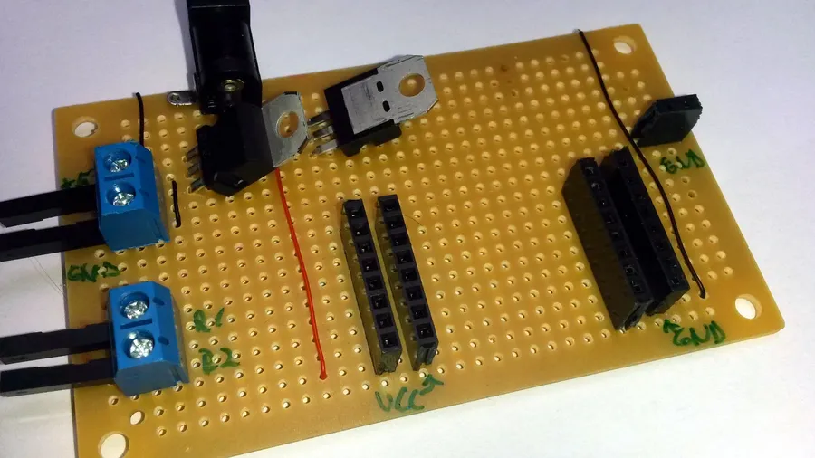
Dedicated power rails are crucial for distributing power efficiently across the stripboard. This is especially important for complex designs. Power rails typically consist of a set of parallel tracks dedicated for power (VCC) and ground (GND) connections. These are typically created using dedicated solid wire soldered to the end of each track, creating a robust power distribution system that minimises voltage drops across the board. - Surface Mount Device (SMD) Integration
Adapting stripboard for surface mount devices (SMD) presents a significant challenge. Using SMD adapter boards or 'breakout boards' can allow for these components to be connected. This method can be combined with fine-gauge wiring to form more complex circuits using these smaller components. - Signal Integrity Considerations
At higher frequencies, signal integrity becomes a key concern. Minimizing trace lengths, avoiding sharp bends in traces, and using ground planes can help maintain signal quality and reduce the effects of interference, reducing signal loss and cross-talk between circuit elements. Implementing a ground plane requires creating a large conductive surface by connecting multiple ground traces together. - Thermal Management
For circuits that generate significant heat, it's crucial to ensure proper thermal management. This can involve using heat sinks, selecting components with good thermal performance, or leaving extra space between heat-generating components on the board to dissipate heat. The careful placement of heat-generating elements and the usage of thermal pads can prevent circuit failure and increase component longevity. - Optimised Layout Design
Creating efficient layouts requires careful planning, using jumpers and wire links effectively, and designing layouts with a clear signal flow. Optimised layout also reduces errors, improving troubleshooting and overall reliability. The placement of components should be dictated by their function, with components that interact frequently placed close together, which helps minimise track lengths and overall signal paths.
Stripboard offers a unique blend of flexibility and reliability, making it a favorite for many electronics projects. It's a versatile platform to test designs before finalizing a custom PCB and allows for creativity in circuit construction. By understanding its structure, mastering soldering, and utilizing the best design practices, you can bring your electronic concepts to life with [stripboard]. This guide has equipped you with the knowledge to excel in the realm of prototyping, paving the way for countless successful projects. Embrace the potential of stripboard, and continue innovating in the world of electronics.