MCPCB: The Ultimate Guide to Metal Core PCBs
In today's fast-paced tech world, where devices pack more power into smaller spaces, effective heat management is crucial. Enter the Metal Core Printed Circuit Board, or MCPCB. This isn't your typical circuit board; it’s engineered with a metal base, often aluminum or copper, offering superior thermal conductivity to dissipate heat efficiently, crucial for high-performance electronics. This article delves into MCPCB technology, unraveling its structure, benefits, and applications, and aims to highlight why this technology is critical for modern engineering.
What is a Metal Core PCB (MCPCB)?
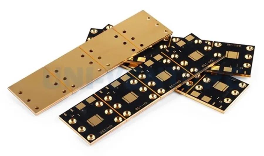
Metal Core PCBs (MCPCBs), also referred to as metal-backed PCBs or thermal PCBs, are printed circuit boards distinguished by their use of a metal base—typically aluminum or copper—instead of the conventional FR4 substrate. This metal core's primary function is to provide a highly efficient thermal pathway, significantly improving heat dissipation compared to standard PCBs, which is crucial for managing thermal loads in high-power electronics applications.
MCPCB Structure: Key Components
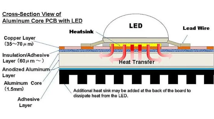
Metal Core PCBs (MCPCBs) are engineered for efficient thermal management, and their structure is pivotal to achieving this. The core design incorporates three essential layers: a metal base, a dielectric layer, and a copper foil layer, each serving a specific function in the board's operation.
| Component | Function | Material Example |
|---|---|---|
| Metal Base | Provides structural support and acts as a heat sink, dissipating heat away from the components. | Aluminum, Copper |
| Dielectric Layer | Offers electrical insulation between the metal base and the copper circuitry, ensuring proper circuit function without shorting. | Ceramic-filled polymer, thermally conductive epoxy |
| Copper Foil Layer | Forms the conductive paths for the electrical signals and power. It is etched to create the required circuit pattern. | Electrodeposited Copper |
The interplay between these components is critical for the overall performance of the MCPCB. The metal base's ability to rapidly transfer heat, coupled with the dielectric's capacity to provide electrical insulation, and the precise pattern of the copper layer, enables these boards to excel in applications where heat management and reliability are essential.
Advantages of Using MCPCBs
Metal Core Printed Circuit Boards (MCPCBs) present several key advantages over traditional FR4 PCBs, primarily in thermal management, durability, and dimensional stability. These benefits make MCPCBs particularly well-suited for demanding high-power applications where heat dissipation is crucial.
- Superior Heat Dissipation
The most significant advantage of MCPCBs is their exceptional ability to dissipate heat. The metal core, typically aluminum or copper, provides a highly conductive path for heat to travel away from heat-generating components, preventing thermal buildup and ensuring stable operation. This is particularly important in high-power applications such as LED lighting and power electronics where effective thermal management is crucial. The thermal conductivity of aluminum and copper significantly surpasses that of FR4, which is an insulator, resulting in a lower operating temperature. - Improved Durability and Mechanical Strength
MCPCBs exhibit greater mechanical strength and durability compared to FR4 PCBs, due to the robust metal core. This provides better resistance to mechanical stresses and deformation, reducing the likelihood of damage from vibration, impact, or rough handling. This enhanced robustness is critical in harsh operating environments and for applications where structural integrity is paramount. - Enhanced Dimensional Stability
The metal core of MCPCBs offers a higher degree of dimensional stability when compared with FR4. This reduces the coefficient of thermal expansion (CTE) and ensures the circuit board maintains its shape and dimensions when faced with temperature changes. This stability is essential in preventing stress on soldered connections and ensuring reliable performance over a wide temperature range, especially in precision applications. - Longer Lifespan
The efficient heat dissipation capabilities of MCPCBs lead to a lower operating temperature for components. This reduces thermal stress on solder joints and electronic components, thus increasing the overall lifespan and reliability of the electronic device and reducing maintenance requirements, particularly in long-term or critical applications. Heat is a major cause of component failure, and MCPCBs mitigate this risk. - Higher Power Density
Due to their superior thermal performance, MCPCBs can operate at higher power densities without the risk of overheating. This allows for more compact and efficient designs, reducing the size and weight of the overall product, crucial in applications where space is at a premium. This higher density is achievable by ensuring efficient heat extraction, keeping components within safe operating limits. For example, high-brightness LED arrays benefit from this, facilitating more powerful light sources in a smaller package.
Materials Used in MCPCBs: Aluminum vs. Copper
The selection of materials for Metal Core PCBs (MCPCBs) is pivotal, directly influencing performance and cost. Aluminum and copper are the predominant choices, each offering distinct advantages and disadvantages, tailored to specific application requirements.
| Feature | Aluminum MCPCB | Copper MCPCB |
|---|---|---|
| Thermal Conductivity | Moderate (200-250 W/m·K) | High (380-400 W/m·K) |
| Cost | Lower | Higher |
| Weight | Lightweight | Heavier |
| Corrosion Resistance | Good | Good (may require surface treatment) |
| Mechanical Strength | Good | Good |
| Common Applications | General LED lighting, low-power electronics | High-power LEDs, automotive, aerospace applications |
The selection between aluminum and copper for an MCPCB is a trade-off based on thermal requirements, cost constraints, and application context. While aluminum offers a cost-effective solution for many applications with sufficient heat dissipation, copper is the premium choice for high-performance scenarios demanding superior thermal management despite the additional cost and weight.
MCPCB Applications: Where are they used?
Metal Core PCBs (MCPCBs) are essential in applications that demand efficient heat dissipation, offering a significant advantage over traditional FR4 PCBs. Their ability to manage thermal loads makes them ideal for a variety of high-power and temperature-sensitive applications.
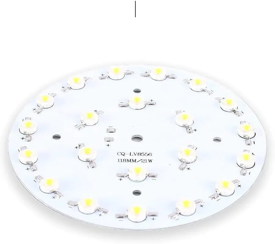
- LED Lighting
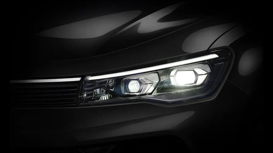
MCPCBs are extensively used in LED lighting applications due to their excellent heat dissipation capabilities. This is crucial for maintaining the performance and lifespan of LEDs, particularly in high-brightness and high-power LED systems like streetlights, automotive headlights, and architectural lighting. The metal core efficiently draws heat away from the LEDs, preventing overheating and ensuring consistent light output. - Automotive Electronics
The automotive industry utilizes MCPCBs in various applications where reliability and thermal management are critical. This includes engine control units (ECUs), power converters, LED lighting systems (both interior and exterior), and advanced driver-assistance systems (ADAS). The robust nature of MCPCBs ensures that these sensitive electronic components function reliably under the harsh conditions experienced in vehicles. - Power Electronics
High-power electronics applications, such as power supplies, inverters, and converters, benefit significantly from the superior thermal performance of MCPCBs. These applications generate considerable heat, which must be efficiently managed to ensure stable operation and to avoid damage to the components. MCPCBs allow for higher power densities and better overall performance in these systems. - Motor Control Systems
In motor control applications, where significant power is used to operate motors, MCPCBs provide the necessary heat management to keep the driver circuitry within safe operating temperatures. The increased efficiency allows for more compact designs and higher output. - High-Intensity Lighting Systems
MCPCBs are ideal for high-intensity lighting systems such as those found in commercial spaces and industrial settings, where maintaining a safe operating temperature of the LEDs is important. By using a metal core, heat can be quickly dissipated away from the LEDs. - Other Applications
MCPCBs also find use in a wide variety of applications such as solar power systems, industrial automation equipment, and aerospace systems where thermal management and reliability are crucial.
The Manufacturing Process of MCPCBs
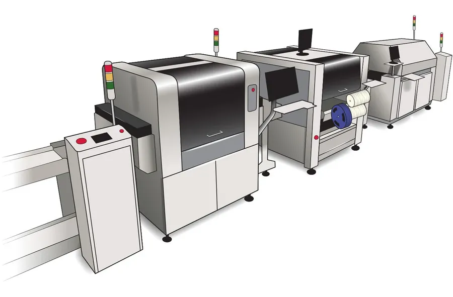
The fabrication of Metal Core Printed Circuit Boards (MCPCBs) is a meticulous process, requiring precision at each stage to ensure optimal thermal and electrical performance. It involves the controlled layering of various materials, creating a robust and efficient heat-dissipating substrate for electronic components.
- Metal Core Preparation
The process begins with the selection and preparation of the metal base, typically aluminum or copper. The metal sheet is cleaned and pre-treated to ensure good adhesion with the subsequent layers. This initial step is critical to the overall reliability of the MCPCB, preventing delamination and ensuring effective thermal transfer. - Dielectric Layer Application
A thin layer of thermally conductive, electrically insulating dielectric material is then applied to the prepared metal core. This layer is crucial for both electrical isolation and thermal conductivity. The material used in this layer is a specialized polymer or ceramic designed to enhance heat transfer while preventing electrical shorts. Common materials used include epoxy resins, polyimide, or ceramic-filled compounds. The application method (lamination, spray, or coating) is selected based on the required thickness and material properties. - Copper Foil Lamination
A thin layer of copper foil is laminated onto the dielectric layer. This copper foil forms the conductive layer where the circuit traces will be etched. The lamination process must be carefully controlled to ensure uniform adhesion and minimize the risk of voids or air gaps that could impede thermal transfer or cause electrical issues. The copper thickness and type is selected based on the current requirements of the circuit. - Circuit Patterning
The desired circuit pattern is transferred onto the copper foil through a process of photolithography. A photosensitive resist is applied to the copper, exposed to UV light through a mask of the circuit design, and then developed. This exposes the areas of copper that will be etched away, while the resist protects the required traces. The etching process then removes the unwanted copper, leaving the desired circuit traces. This process requires fine control of the etchants, temperatures, and time to achieve high accuracy in trace definition. - Solder Mask Application
A solder mask layer is applied over the exposed circuit traces to protect them from oxidation and to define the areas where components will be soldered. This solder mask is typically a thin, curable polymer and is applied by silk screening, spraying, or curtain coating, followed by a UV curing process. This step is essential to ensure that during the soldering process, solder flows only to the desired areas, preventing shorts between traces. - Surface Finishing
The MCPCB undergoes a surface finishing process to enhance solderability, protect the copper from corrosion, and provide good electrical contact points. Common surface finishes include HASL (Hot Air Solder Leveling), ENIG (Electroless Nickel Immersion Gold), and immersion tin. The selection of the surface finish depends on the application's environment and the desired lifespan of the board. - Final Testing and Inspection
The completed MCPCB undergoes rigorous testing to ensure that it meets all electrical and thermal performance requirements. This testing may involve electrical tests for shorts and opens, thermal resistance testing, and visual inspection. Any boards that fail to meet the specifications are either reworked or rejected. This final testing step ensures high-quality and reliable product.
MCPCB Design Considerations
Designing Metal Core Printed Circuit Boards (MCPCBs) requires a multi-faceted approach, focusing on material selection, thermal management, and electrical performance to ensure optimal functionality and longevity. Careful consideration of these interconnected aspects is crucial for creating reliable and efficient MCPCBs.
Key design factors include:
- Metal Core Thickness
The thickness of the metal core, typically aluminum or copper, directly impacts the MCPCB's heat dissipation capacity and mechanical strength. Thicker cores enhance thermal performance but may add weight and cost. The selection should be based on the application's heat load requirements and mechanical constraints. - Dielectric Layer Properties
The dielectric layer provides electrical insulation between the metal core and copper circuitry. Its thermal conductivity, dielectric constant, and thickness are crucial for both thermal performance and electrical signal integrity. Materials with high thermal conductivity, such as thermally conductive epoxies or ceramics, are often used to minimize thermal resistance. - Copper Trace Routing
The routing of copper traces on an MCPCB needs to consider both electrical performance and heat dissipation. Wide traces can carry higher currents and aid in heat spreading. Careful placement of heat-generating components and vias is essential to facilitate efficient thermal transfer to the metal core. Trace impedance must also be considered for signal integrity. - Material Selection
Choosing the correct materials for the metal core, dielectric layer, and copper circuitry is paramount. Each material has unique thermal and electrical properties that impact the performance of the MCPCB. Aluminum provides a cost-effective, lightweight solution for many applications, while copper offers higher thermal conductivity but is more expensive. The dielectric material must provide adequate insulation and thermal performance. - Thermal Management
Effective thermal management is critical. The design must account for the heat generated by components and facilitate its transfer through the dielectric layer to the metal core and subsequently to the heatsink or ambient environment. Techniques include using thermal vias, heat spreaders, and optimized trace widths to improve heat dissipation. - Component Placement
The placement of heat-generating components should consider their proximity to the metal core and how effectively heat can be conducted away. Strategically placing higher power components closer to the center of the board or directly on top of thermal vias can significantly improve heat dissipation.
Frequently Asked Questions About Metal Core PCBs (MCPCBs)
This section addresses common questions regarding Metal Core PCBs (MCPCBs), clarifying their functionality, benefits, and applications. We aim to provide clear and concise answers to help you better understand MCPCBs and their use cases.
- What exactly is a Metal Core PCB (MCPCB)?
A Metal Core PCB (MCPCB), also known as a metal-backed PCB or thermal PCB, is a printed circuit board that uses a metal base, typically aluminum or copper, instead of the conventional FR4 material. This metal core serves primarily as a heat sink, efficiently drawing heat away from the electronic components mounted on the board. - What are the primary differences between FR4 PCBs and MCPCBs?
The fundamental difference lies in the base material. FR4 PCBs use a fiberglass composite, which is a poor thermal conductor, while MCPCBs utilize a metal core known for high thermal conductivity. Consequently, MCPCBs are far superior in heat dissipation, making them ideal for high-power applications where heat management is crucial, whereas FR4 boards are more suited to general purpose, low power applications. - What does 'MCPCB LED' refer to?
MCPCB LED refers to the application of MCPCB technology in LED lighting. The metal core in an MCPCB efficiently dissipates the heat generated by high-power LEDs, which is essential to maintain performance and extend the lifespan of LED lighting systems. Because of the need for efficient thermal management of high powered LEDs, they are frequently used in MCPCBs. - What factors influence the cost of MCPCBs?
The cost of MCPCBs is primarily influenced by several factors, including the type of metal used (copper being more expensive than aluminum), the thickness of the metal core, the complexity of the circuit design, the dielectric material used and the production volume. Higher thermal conductivity and more complex designs generally lead to increased costs. - How does the thermal conductivity of MCPCBs compare to FR4 PCBs?
MCPCBs exhibit significantly higher thermal conductivity compared to FR4 PCBs. The metal core in MCPCBs can have a thermal conductivity of up to 200-400 W/mK, while FR4 has a thermal conductivity around 0.2-0.3 W/mK. This huge difference makes MCPCBs ideal for heat intensive applications. - Can MCPCBs be used in automotive applications?
Yes, MCPCBs are frequently used in automotive electronics, particularly in areas like LED headlights, power modules, and engine control units. The durability and heat dissipation properties of MCPCBs make them well-suited to withstand the harsh operating conditions in vehicles. - What are the common metal types used in MCPCBs and what are their characteristics?
The two most common metals are aluminum and copper. Aluminum is cost-effective, lightweight, and offers good thermal conductivity. Copper, while more expensive and heavier, provides superior thermal conductivity, making it suitable for extremely high-power applications. The choice between the two depends on cost, weight, and performance requirements.
MCPCB vs. FR4: A Detailed Comparison
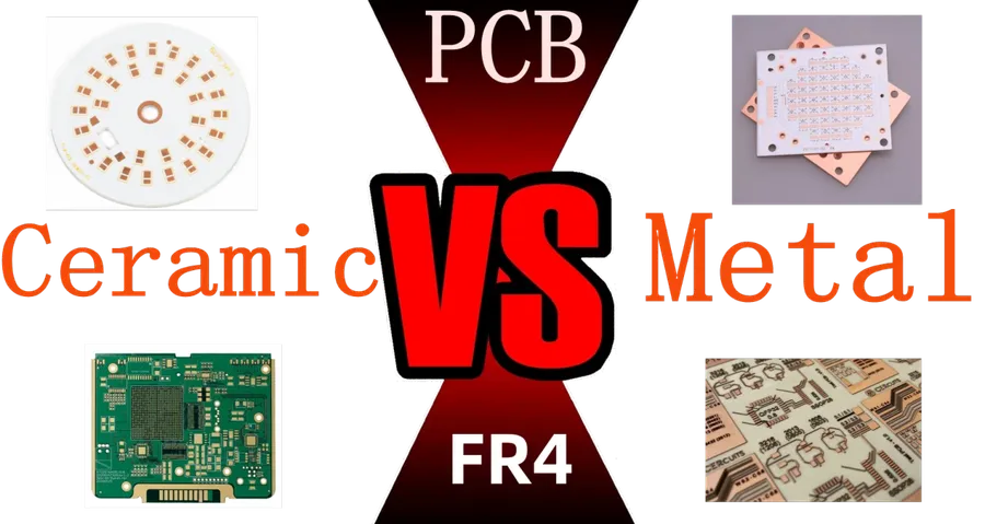
This section provides a direct comparison between Metal Core PCBs (MCPCBs) and traditional FR4 PCBs, focusing on key differences that influence their suitability for various applications. Understanding these distinctions is crucial for making informed decisions about PCB selection.
| Feature | MCPCB | FR4 PCB |
|---|---|---|
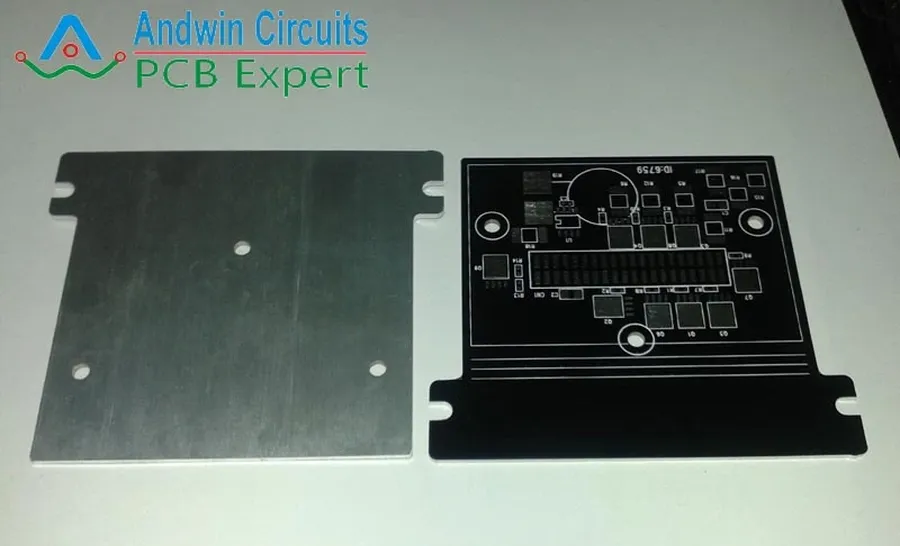
| Base Material | Metal (Aluminum or Copper) | Fiberglass reinforced epoxy (FR4) |
| Thermal Conductivity | High | Low |
| Heat Dissipation | Excellent | Poor |
| Dimensional Stability | High | Moderate |
| Cost | Higher | Lower |
| Durability | High | Moderate |
| Typical Applications | High-power LED lighting, power electronics, automotive | General-purpose electronics |
| Weight | Moderate to High | Low to Moderate |
| Manufacturing Complexity | More Complex | Less Complex |
| Layer Count | Typically single or double sided | Multi-layer possible |
The table above highlights the key differences between MCPCBs and FR4 PCBs. MCPCBs excel in thermal management, making them ideal for applications generating significant heat, while FR4 PCBs are more cost-effective for general-purpose electronics where thermal performance is less critical.
In conclusion, MCPCB technology is vital for modern electronic design, offering crucial heat management that extends the lifespan and enhances the performance of devices. With a superior thermal core, they surpass traditional FR4 boards in applications with high heat output. As technology continues to advance, the role of MCPCBs in electronics will become even more critical, making them an essential component for engineering reliable and efficient systems. Whether in lighting, automotive, or power electronics, choosing MCPCB can significantly improve product quality and performance.