Solderable Breadboard: A Comprehensive Guide for Electronics Enthusiasts
In the dynamic world of electronics, prototyping is a crucial step, and the solderable breadboard emerges as a reliable ally. Unlike its solderless counterpart, a solderable breadboard allows for robust, semi-permanent connections, mirroring the real world applications of electronics projects. This article delves deep into understanding solderable breadboards, their benefits, and how to use them effectively to bring your electronic creations to life.
What is a Solderable Breadboard?
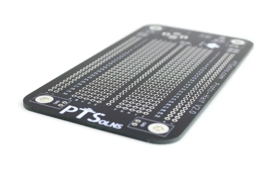
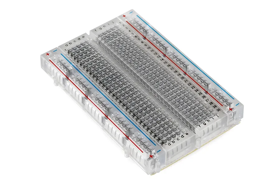
A solderable breadboard is a printed circuit board (PCB) that replicates the layout of a solderless breadboard, enabling users to permanently secure electronic components via soldering, thus creating a more durable and reliable circuit compared to a solderless setup.
Key Features of a Solderable Breadboard
Solderable breadboards are designed to provide a robust platform for prototyping electronic circuits, mimicking the familiar layout of solderless breadboards while allowing for permanent connections through soldering. They incorporate several key features to facilitate circuit design and construction. These features include connection points, power rails, grid layouts, and material variations.
- Connection Points
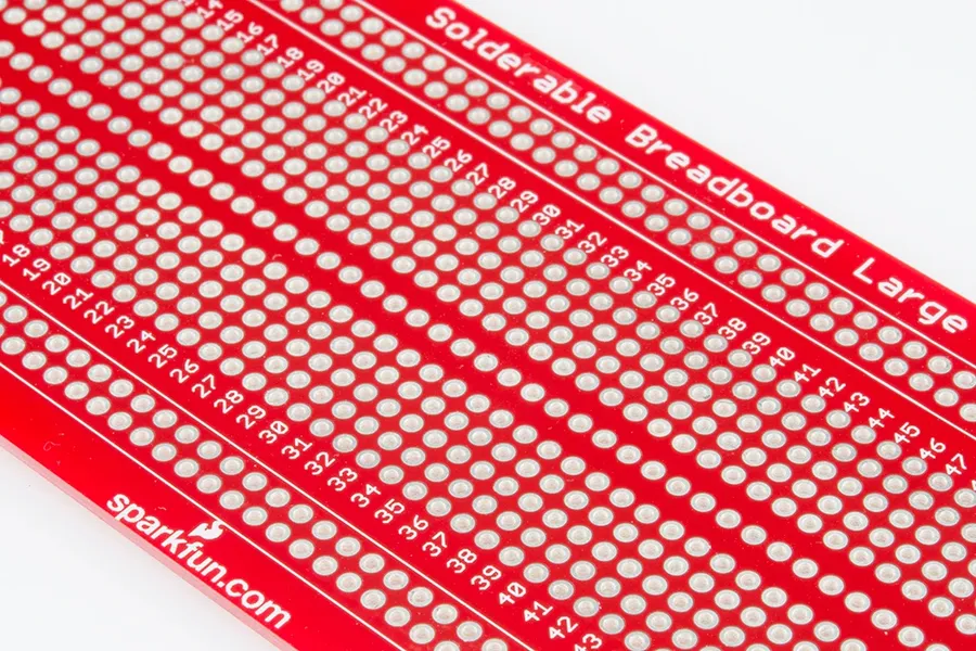
Solderable breadboards feature plated through-holes arranged in a standard grid pattern (typically 0.1 inch or 2.54 mm spacing), which corresponds to the spacing on integrated circuits (ICs) and other electronic components. These holes serve as solder points, facilitating the connection of component leads and wires. - Power Rails
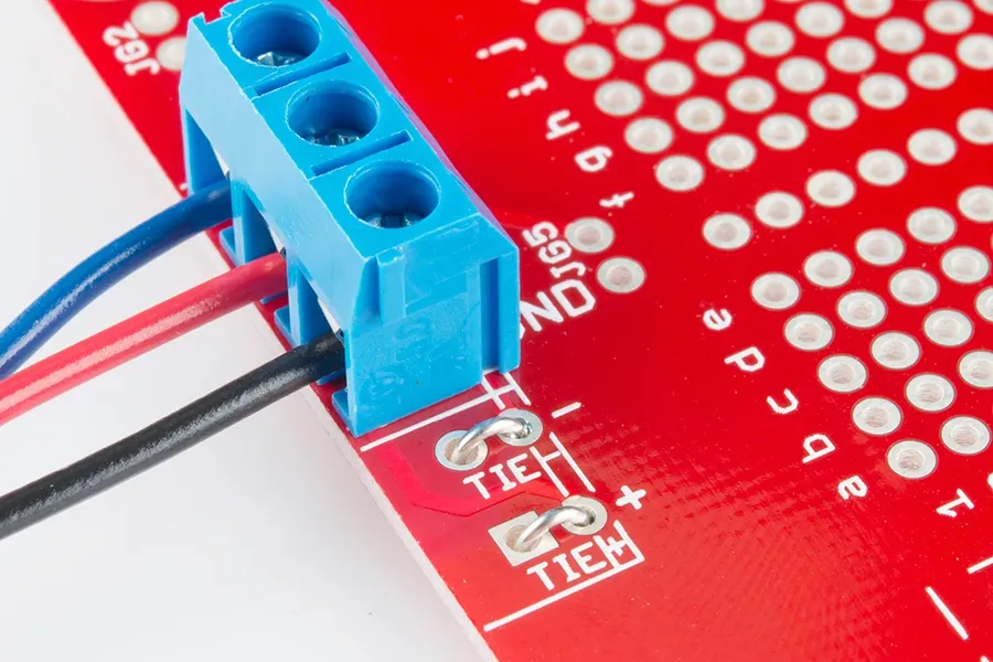
Many solderable breadboards include dedicated power rails running along the edges. These rails are typically marked with (+) and (-) symbols or color-coded for easy identification. They provide convenient access points for distributing power to various parts of the circuit, simplifying wiring and reducing clutter. Some boards feature multiple power rails or split rails for added flexibility. - Grid Layout
The standard 0.1-inch (2.54mm) grid layout is fundamental to solderable breadboards. This grid pattern allows for easy integration of DIP (Dual In-line Package) ICs, resistors, capacitors, and other through-hole components. The consistent spacing ensures that most standard electronic parts will fit precisely on the breadboard. - Material Variations
Solderable breadboards are typically made from FR-4, a common material in printed circuit board (PCB) manufacturing, known for its durability, electrical insulation, and resistance to heat. The thickness and quality of the FR-4 can vary, impacting the overall robustness of the breadboard. Some boards may feature copper plating on the through-holes to improve solderability and prevent oxidation. - Size Variations
Solderable breadboards come in a variety of sizes, from small, compact boards for simple projects to larger boards designed to accommodate more complex circuits. These variations allow users to select a board that best suits their project requirements and spatial constraints. Some boards will also incorporate mounting holes to allow it to be attached to a base for enhanced stability.
Solderable Breadboard vs. Solderless Breadboard
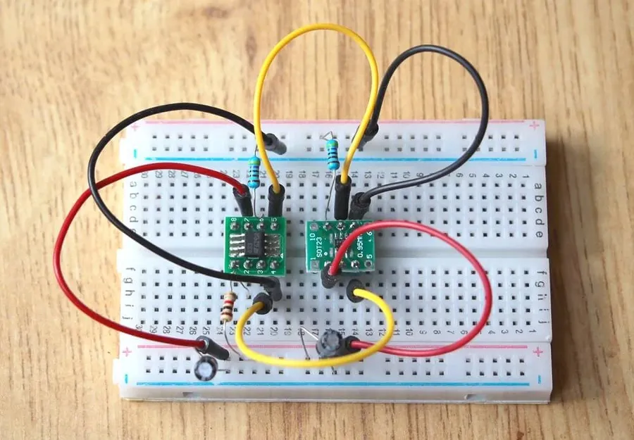
Solderable and solderless breadboards serve distinct purposes in electronics prototyping. Solderable breadboards offer a more robust, semi-permanent solution, while solderless breadboards are designed for rapid, non-permanent circuit experimentation. The choice between them hinges on the project's requirements for stability, longevity, and ease of modification.
| Feature | Solderable Breadboard | Solderless Breadboard |
|---|---|---|
| Connection Type | Soldered connections | Spring-loaded contacts |
| Connection Reliability | High, permanent and vibration resistant | Moderate, can be unreliable if not properly inserted or from physical disturbance |
| Durability | Robust, suitable for semi-permanent use and final prototypes | Fragile, best for temporary setups |
| Modification | Difficult to modify once soldered, requiring desoldering | Easy to modify, components can be re-arranged quickly |
| Current Handling | Better, soldered connections can handle higher currents | Limited, spring contacts are prone to over-heating or arcing |
| Skill Level Required | Requires soldering skills | Requires no soldering skills |
| Cost | Slightly higher, due to PCB construction | Lower |
| Typical Use Cases | Semi-permanent prototypes, final circuits, where stable and robust connections are needed | Quick prototyping, educational purposes, temporary circuit testing, breadboard circuit experimentation |
Step-by-Step Guide to Using a Solderable Breadboard
Effectively using a solderable breadboard requires careful planning and execution. This section provides a detailed, step-by-step guide to ensure reliable and robust connections for your electronic projects, covering everything from component preparation to final soldering.
- Prepare Components and Wires
Begin by gathering all necessary electronic components, ensuring they are compatible with the project's requirements. Cut wires to the appropriate lengths, stripping the insulation from the ends to expose the bare conductors. Tinning the exposed wire ends with solder before placing them onto the board will help ensure a solid solder joint. - Plan the Layout
Before soldering, plan the component layout, referring to schematics or project designs. Place components on the board and identify the connection paths. Test the layout and circuit using a solderless breadboard if you are unsure. This layout is your guide for soldering, so accuracy is crucial. Avoid placing too many components in one area to ensure you have space for wires and the heat from soldering. - Component Placement
Carefully position the components on the solderable breadboard, ensuring that they align with the planned layout. Make sure to not push the component leads all the way through the board. This makes soldering easier and allows for some movement of the components for adjustment. - Soldering the Components
Using a soldering iron at the correct temperature, solder each component lead to its corresponding pad on the solderable breadboard. Ensure that each solder joint is shiny and smooth, not dull or blobby. This indicates a good electrical connection. Use proper techniques and materials for robust joints. Apply solder evenly to both the component lead and the board's pad. - Wiring the Connections
After soldering the components, add wires to complete the circuit connections. These should be placed and soldered in the same manner as the component leads, ensuring they make good contact. Be sure to double-check the connection paths and that the wires are correctly routed to avoid shorts or incorrect circuits. - Testing and Verification
Following the completion of soldering, test the circuit thoroughly using a multimeter or other suitable testing equipment. Check all connection points to ensure there are no shorts or open circuits. Verify that the circuit functions as intended, making adjustments as necessary. - Final Inspection
Once satisfied with the circuit's performance, give the entire board a final inspection. Look at solder joints to ensure they are complete and that wires and components are securely connected. Clean any flux residue from the board, and your solderable breadboard is ready.
Soldering Best Practices for Solderable Breadboards
Achieving reliable and durable connections on a solderable breadboard hinges on employing proper soldering techniques. This section outlines the critical practices, including temperature management, wire tinning, and creating robust solder joints, to ensure optimal results for your electronics projects.
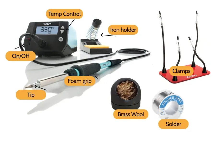
- Temperature Control
Maintaining the correct soldering iron temperature is crucial. Too low, and the solder won't flow properly, creating a weak joint; too high, and you risk damaging components or the breadboard itself. A temperature range of 315-370°C (600-700°F) is generally suitable for most electronic soldering applications. It's recommended to calibrate your soldering iron and verify its accuracy. - Tinning Wires
Before soldering wires to the breadboard, tinning the exposed ends is essential. This process involves applying a thin layer of solder to the wire. Tinning provides a clean and readily solderable surface, enhancing solder flow and joint strength. Use a flux-cored solder to aid in wetting the wire. Ensure the wire is heated adequately to allow the solder to flow evenly. - Creating Strong Solder Joints
The objective is to achieve a concave fillet, where the solder smoothly transitions from the component lead or wire to the pad on the breadboard. To achieve this, heat both the lead/wire and the pad simultaneously. Apply solder to the heated junction, ensuring it flows and wets the surfaces fully, Avoid dry or cold joints which can become intermittent, especially under thermal stress. Ensure that sufficient solder is used, but avoid excess that can cause bridging between adjacent pins. Allow the solder to cool and solidify without movement. - Flux Application
Flux is a chemical cleaning agent that is essential for good solder joints. It removes oxides from the surfaces being soldered, allowing solder to flow freely. Most solder used for electronics contains a flux core, but additional flux can be beneficial, particularly when using lead-free solder. Apply flux to the joint just before soldering. - Safety Precautions
Soldering involves high temperatures and potentially harmful fumes. Always work in a well-ventilated area or use a fume extractor. Wear safety glasses to protect your eyes from solder splashes. Handle the soldering iron with care to avoid burns. Unplug the iron when not in use, and store the hot iron in a fire-resistant stand.
Advantages of Using a Solderable Breadboard
Solderable breadboards offer distinct advantages over their solderless counterparts, primarily in the areas of connection stability, reliability, and suitability for more demanding electronic projects. These benefits make them an excellent choice when building prototypes that require a more robust construction, especially when moving toward a final design.
- Enhanced Stability:
Soldered connections provide a physical and permanent bond, significantly reducing the risk of accidental disconnections or loose components. This is particularly beneficial for projects that will be moved or subjected to vibrations. - Superior Connection Reliability:
Unlike the friction-based contacts in solderless breadboards, soldered joints ensure a solid electrical connection. This reduces the chance of intermittent connections and signal disruptions, leading to more stable and reliable circuit operation. - High-Current Handling:
Solderable breadboards can handle higher currents compared to solderless breadboards. This makes them ideal for projects that require more power, such as those involving motors, high-power LEDs, or other current-intensive components. - Suitable for Permanent Prototypes:
Solderable breadboards are well-suited for creating semi-permanent or final prototypes. The soldered connections enable projects to be robust and durable, ready for long-term operation or further development. - Professional Appearance:
Projects built on a solderable breadboard often have a cleaner and more professional appearance than those on solderless boards, especially with carefully planned component layout and neat soldering.
| Feature | Solderable Breadboard | Solderless Breadboard |
|---|---|---|
| Connection Stability | High (Soldered) | Low (Friction Fit) |
| Connection Reliability | High | Medium |
| Current Capacity | High | Low |
| Permanence | Semi-Permanent | Temporary |
| Durability | High | Low |
Disadvantages of Using a Solderable Breadboard
While solderable breadboards offer significant advantages for prototyping, they also present certain drawbacks. These limitations primarily stem from the semi-permanent nature of soldered connections, the potential need for rework, and the elevated skill level required for effective utilization.
- Semi-Permanence
Soldered connections are not easily reversible. Once a component is soldered onto the board, it's not designed to be easily moved or removed. This limits the flexibility for rapid prototyping iterations and design changes compared to solderless breadboards. - Rework Complexity
If a mistake is made, components need to be desoldered and replaced. Desoldering can be challenging, especially for multi-pin components, and can potentially damage the components or the breadboard if not done carefully, making rework a time consuming and delicate process. - Skill Requirement
Soldering requires a moderate level of skill and practice to achieve reliable, high-quality connections. Inexperienced users might encounter difficulties creating strong solder joints, leading to unreliable circuits. Proper tools, such as a soldering iron, solder, and desoldering equipment, are also required. - Less Flexibility for Quick Changes
Compared to solderless breadboards, where components can be quickly plugged and unplugged, making design changes on a solderable breadboard takes much longer. This is a limitation when iterative design changes need to be made frequently during the prototyping phase. - Potential for Damage
Repeated soldering and desoldering on the same pads can lead to damage of the breadboard's copper traces, solder pads, and the overall integrity of the board. This can shorten the lifespan of the breadboard. Furthermore, excess heat during soldering can damage heat-sensitive components.
Frequently Asked Questions About Solderable Breadboards
This section addresses common questions and concerns regarding solderable breadboards, providing practical insights for users ranging from beginners to experienced electronics enthusiasts. These frequently asked questions will help clarify the selection, usage, and troubleshooting of solderable breadboards.
- What exactly is a solderable breadboard?
A solderable breadboard is a printed circuit board (PCB) that mimics the layout of a traditional solderless breadboard. Instead of using spring clips to hold components, it features plated through-holes and conductive pads, enabling permanent connections via soldering. This provides a more robust and reliable platform for electronic prototypes. - Can you solder wires directly to a traditional (solderless) breadboard?
No, you should not solder wires directly to a traditional solderless breadboard. The internal spring clips and plastic housing are not designed to withstand the heat of soldering, and you risk damaging or melting them. Solderless breadboards are intended for temporary, non-permanent circuit connections, unlike solderable breadboards. - What are the key differences between solderable and solderless breadboards?
Solderless breadboards are designed for rapid prototyping and experimentation. They allow for quick component changes and reuse, but they are not ideal for permanent connections due to their fragility and less reliable contacts. In contrast, solderable breadboards are designed for semi-permanent or final prototypes. They provide more reliable electrical connections but are less flexible than solderless breadboards, once components have been soldered. - What is the typical current limit for a solderable breadboard?
The current limit of a solderable breadboard is determined primarily by the copper traces and solder joints used to make the connections. While standard solderable breadboards do not have a specific rated current limit as this is very dependent on the components and layout, generally can handle higher currents than their solderless counterparts due to the more reliable soldered connections and copper tracks. However, for higher power applications, you should consider the current-carrying capacity of the solder joints, tracks and components. Always refer to the specifications of your chosen components and breadboard. - How do I choose the right solderable breadboard for my project?
Choosing the right solderable breadboard depends on your project's specific needs. Consider the size and number of connection points required, the spacing between the holes, and whether power rails are available. Look for materials that are durable and resistant to heat during soldering. Also, the physical size and mounting holes may be important for fitting within your project. - Where can I purchase a solderable breadboard?
Solderable breadboards are available from a variety of sources including electronics retailers, online marketplaces, and specialized electronics suppliers. Some popular options include Amazon, Mouser, and the ElectroCookie website. Consider both price and quality when making your purchase. - What should I do if a solder joint fails on a solderable breadboard?
If a solder joint fails, carefully inspect the joint for cracks or insufficient solder. To fix it, you may need to remove the component, clean the pads, and then resolder. If a joint has too much solder, use a desoldering braid to remove the excess. Additionally, make sure your soldering equipment is at the correct temperature and the surfaces are clean prior to soldering.
Advanced Tips and Tricks for Solderable Breadboards
Mastering the art of using solderable breadboards extends beyond basic soldering. This section delves into advanced techniques to maximize the functionality and reliability of your projects. We'll cover effective use of jumper wires, strategic component mounting, and essential heat management strategies.
- Using Jumper Wires for Complex Connections
When your design requires connections that span across the breadboard, or if you need to make temporary connections, consider using jumper wires. These wires, with their insulated housing and exposed leads, can be soldered directly to the breadboard’s pads for a secure yet flexible connection. This method is particularly useful for routing signals, especially in dense circuits, or for modifying circuits. Use the correct gauge of wire for the required current. Pre-tinning the ends of the wires aids easy soldering. Always ensure insulation of wires to prevent shorts. - Component Mounting Techniques
Effective component mounting is crucial for a robust and reliable circuit. For components with leads, ensure they are properly seated on the pads before soldering. For components that do not have leads, such as surface mount components, consider using breakout boards to mount these before soldering to the solderable breadboard. For larger components, use mounting brackets or adhesive to prevent movement. This also makes the project more robust. Plan the component layout by considering the circuit design, and use a digital schematic capture tool to plan out the layout. - Implementing Heat Management for Sensitive Components
Heat management is crucial, especially when dealing with sensitive components like microcontrollers, LEDs, or other semiconductors. Heat sinks can be attached to components to dissipate heat. Ensure adequate spacing between components to avoid hot spots. Also when soldering, make sure to use the correct temperature to prevent damage to components. Applying thermal paste between the component and heatsink can enhance heat dissipation.
Solderable breadboards are a bridge between the flexibility of prototyping and the reliability of permanent circuit boards. By understanding their features, benefits, and proper usage, you can significantly enhance your electronics projects, ensuring that your prototypes are robust, reliable, and ready for the next phase of development. For any serious electronics enthusiast a solderable breadboard is an indispensable tool for taking your projects from conception to fruition.