The Ultimate Guide to Inverter PCBs: Design, Function, and Selection
In our increasingly electrified world, inverter PCBs are the unsung heroes, seamlessly converting direct current (DC) to alternating current (AC), powering everything from solar panels to home appliances. This article delves into the crucial role inverter PCBs play, discussing their design intricacies, practical applications, and how to choose the right one for your needs. Join us as we explore the science and engineering behind this vital technology, bridging the gap between raw power and usable energy.
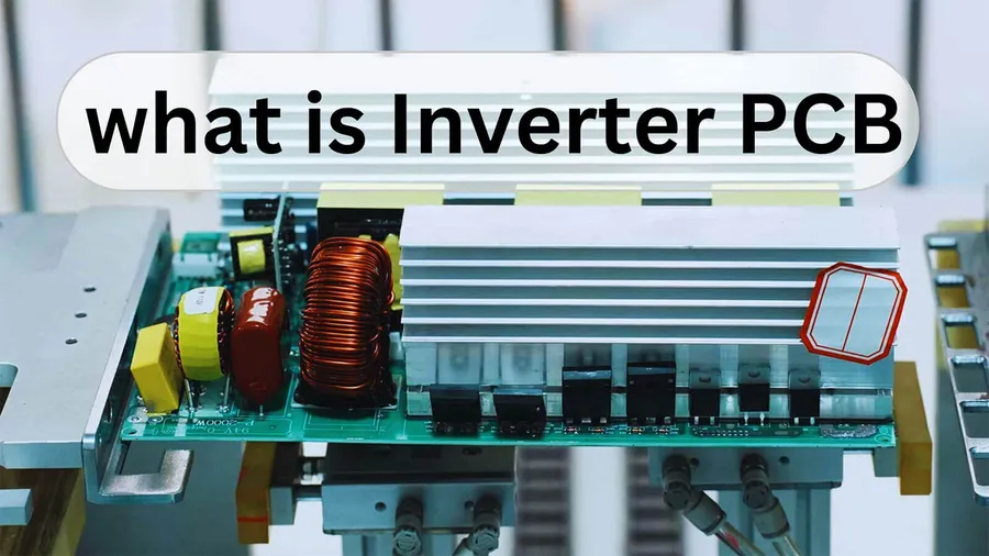
Understanding the Core Function of an Inverter PCB
An inverter Printed Circuit Board (PCB) is fundamentally designed to convert Direct Current (DC) power into Alternating Current (AC) power. This conversion is critical as many power sources, such as batteries and solar panels, provide DC power, while most household and industrial appliances require AC power to operate. The inverter PCB, therefore, acts as a bridge, enabling these devices to function. This process has significantly transformed power management, allowing for efficient and versatile use of electrical energy.
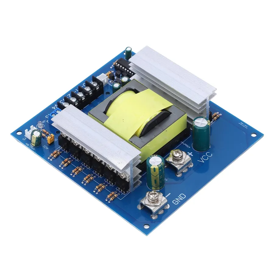
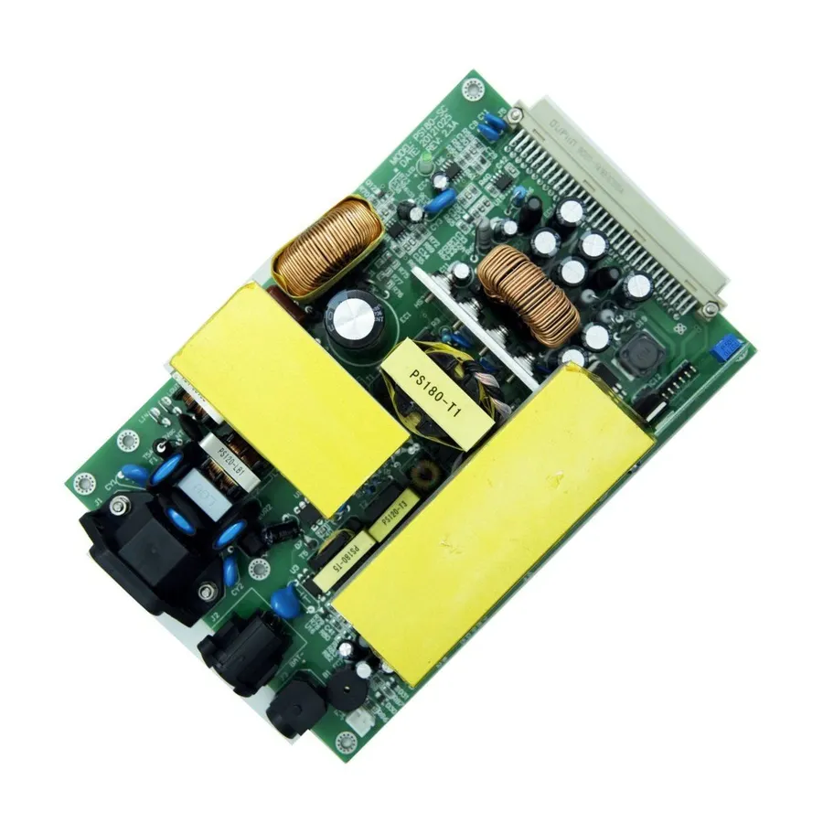
Key Components on an Inverter PCB
An inverter PCB's functionality hinges on the synergistic operation of several critical components. These components orchestrate the conversion of direct current (DC) power into alternating current (AC) power, which is essential for powering a wide range of electronic devices. The following sections detail these key components.
| Component | Function | Material/Technology |
|---|---|---|
| Microcontrollers (MCU) | Serve as the 'brains' of the inverter, executing control algorithms, managing switching, and monitoring system performance. | Typically silicon-based, with embedded firmware. |
| Power Transistors (MOSFETs/IGBTs) | Act as electronic switches, rapidly switching the current to generate the AC waveform. They manage the bulk power conversion process. | Metal-Oxide-Semiconductor Field-Effect Transistors (MOSFETs) are used in lower-power applications, while Insulated Gate Bipolar Transistors (IGBTs) are used for higher-power applications. |
| Capacitors | Used for energy storage and filtering, helping to smooth the DC input and output. They also reduce voltage spikes and electrical noise. | Ceramic, electrolytic, or film-based, chosen based on capacitance, voltage, temperature, and stability requirements. |
| Inductors | Store energy in a magnetic field, used to smooth current waveforms, and are critical for efficient power conversion, often working in conjunction with capacitors. | Typically wound coils, with a core material that affects performance. |
| Integrated Circuits (ICs) | Provide specialized functions such as gate drivers for power transistors, current sensing, protection circuits, and communication interfaces. | Silicon based. |
| Diodes | Allow current flow in one direction only, essential for rectification and preventing reverse current flow, often used in protection circuits. | Silicon-based. |
| Resistors | Control current flow and create voltage dividers, also used for sensing current and providing feedback to the control circuit. | Various compositions, chosen for resistance value and power rating. |
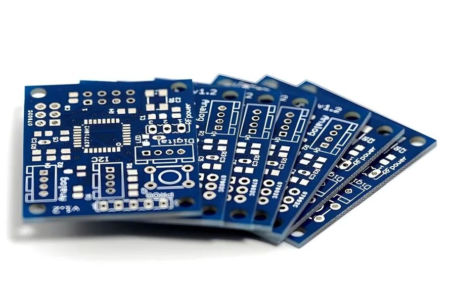
The Significance of PCB Design in Inverter Performance
The Printed Circuit Board (PCB) design is paramount to the performance and reliability of an inverter. A well-designed PCB ensures efficient power transfer, effective heat dissipation, and minimized electromagnetic interference (EMI), all of which directly impact the inverter's longevity and overall performance. Suboptimal design can lead to reduced efficiency, thermal issues, and premature failure of components.
Several critical factors must be meticulously considered during the PCB design phase:
- Trace Width
Trace width dictates the current-carrying capacity of the conductive pathways on the PCB. Insufficient width leads to increased resistance, power loss, and heat generation, while excessive width can be wasteful and cause unwanted effects due to large surface area. The width must be calculated based on current requirements, trace thickness, and thermal considerations, and should align with IPC standards. - Thermal Management
Inverters generate significant heat. Effective thermal management is crucial to prevent overheating and component failure. This involves strategies like optimized component placement, heat sinks, thermal vias, and sufficient copper area for heat dissipation. The PCB material's thermal conductivity and layer stack-up also play critical roles. Simulations should be performed to analyze temperature distribution under various operating conditions, ensuring all parts of the PCB remain within safe temperature tolerances. - Layer Stack-Up
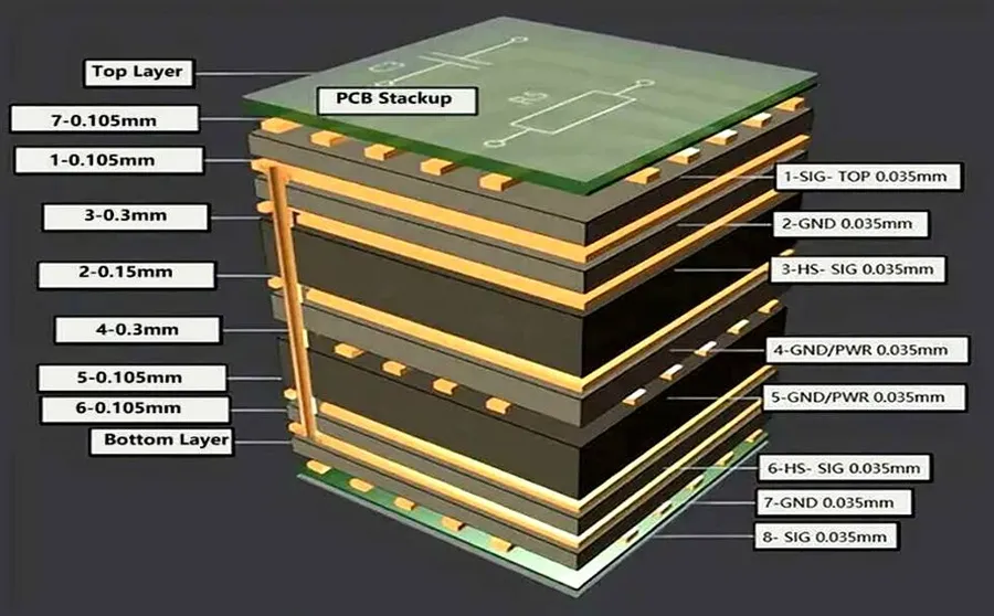
The layer stack-up of a multi-layer PCB affects signal integrity, power distribution, and thermal performance. Correctly configured layers are required for low impedance power distribution, shielding of sensitive signals, and proper heat spreading. A poor layer stack-up can result in increased EMI, power loss, and inefficient thermal management. Considerations should be given to the arrangement of ground and power planes, as well as signal layers. - Component Placement
Strategic component placement minimizes signal path lengths, reduces parasitic effects, and improves thermal management. High-power components must be placed to facilitate effective heat dissipation. Sensitive analog components are isolated from noisy digital components to avoid interference. Furthermore, placement must be optimized for efficient manufacturing, testability, and easy maintenance. Component datasheet thermal ratings must be adhered to during layout
Furthermore, signal integrity and impedance matching must be considered in the high-frequency areas of the inverter PCB to minimize signal reflections and ensure reliable operation. Design tools should be used to simulate and verify the performance of critical signal paths.
Types of Inverter PCBs
Inverter PCBs are not monolithic; they are designed with specific configurations to cater to diverse application needs. This section details the major classifications of inverter PCBs, focusing on single-phase, three-phase, and solar inverters, highlighting their unique designs and suitable applications, and the functional differences between each.
| Type | Description | Typical Applications | Design Characteristics |
|---|---|---|---|
| Single-Phase Inverter PCBs | Convert DC power to single-phase AC power, characterized by one alternating current waveform. They are simpler in design. | Residential power inverters, small-scale UPS systems, and some portable electronics. | Utilize basic switching circuitry with fewer components, making them compact and cost-effective. |
| Three-Phase Inverter PCBs | Convert DC power to three-phase AC power, which involves three alternating current waveforms, each offset by 120 degrees. They are more complex than single-phase types. | Industrial motor drives, large-scale power conversion systems, and some high-power UPS systems. | Include complex switching networks, advanced gate drivers, and robust thermal management systems to handle high power and switching loads. |
| Solar Inverter PCBs | Designed specifically for solar energy systems. Convert DC power from photovoltaic panels to AC power suitable for grid connection or local consumption. | Solar panel systems, grid-tied and off-grid solar installations. | Include Maximum Power Point Tracking (MPPT) controllers, safety features for grid synchronization, and are often designed for high efficiency in varying environmental conditions. |
Inverter PCB Selection Criteria
Selecting the appropriate inverter PCB is crucial for optimal system performance and reliability. This process involves a detailed evaluation of several key parameters to ensure the chosen PCB meets the specific demands of the application. Proper selection prevents failures, maximizes efficiency, and reduces long-term costs.
| Selection Criteria | Description | Importance |
|---|---|---|
| Power Rating | The maximum power the inverter PCB can handle, measured in watts (W) or kilowatts (kW). | Critical for ensuring the PCB can support the load without overheating or damage. Must match or exceed the system's requirements. |
| Input Voltage | The range of DC voltage that the PCB is designed to accept. | Compatibility with the power source (e.g., battery, solar panel) is vital to avoid under-performance or catastrophic failure. |
| Output Voltage | The AC voltage the inverter PCB provides to the load. | Should match the required voltage of the appliance or system being powered to ensure it operates correctly. |
| Frequency | The frequency of the AC output, typically 50 Hz or 60 Hz. | Must align with the standards of the geographic region and the operating requirements of the connected equipment. |
| Efficiency | The percentage of input power converted to output power. Higher efficiency translates to less energy waste. | Impacts operational costs, and reduced heat generation, contributing to the longevity of the PCB and overall system. |
| Application Needs | Specific design features required, based on the intended use case. | Includes factors like environmental conditions (temperature, humidity), protection features (overcurrent, overvoltage) , and regulatory requirements. |
Practical considerations also play a pivotal role in the selection process. Thoroughly analyzing the specific application context helps to further refine choices. For example, solar power inverters need to have maximum power point tracking (MPPT) to optimize energy capture from solar panels. Similarly, in electric vehicles, the inverters must be designed to handle high currents and voltages with high reliability and minimal weight.
Frequently Asked Questions About Inverter PCBs
This section addresses common inquiries regarding inverter PCBs, offering clear and concise answers to enhance your understanding of their function, operation, and repairability. We aim to provide insightful information based on fundamental principles to ensure each answer is both accurate and easily understandable.
- What exactly is an inverter PCB?
An inverter PCB (Printed Circuit Board) is a specialized circuit board designed to convert Direct Current (DC) power into Alternating Current (AC) power. It houses various electronic components such as microcontrollers, power transistors, capacitors, and inductors that work in concert to achieve this conversion. The PCB provides the physical structure and conductive pathways for these components to function effectively as an inverter. - How does an inverter PCB work in AC systems?
In AC systems, the inverter PCB serves as a crucial intermediary for power conversion. It takes DC power, often from sources like batteries or solar panels, and through a process of controlled switching of power transistors, generates an alternating current output. This AC output is then used to power various electrical devices and appliances. This process involves modulating the DC input using pulse width modulation (PWM) or similar techniques to create the desired AC waveform. - What is the primary purpose of the inverter board?
The primary purpose of the inverter board is to provide a reliable and efficient means of converting DC power into AC power. This conversion is essential because many electronic devices and electrical grids operate on AC power, while many renewable energy sources and storage systems provide DC power. Therefore, the inverter board acts as a crucial interface, ensuring compatibility and proper power delivery. - Are inverter PCBs repairable?
Yes, in many cases, inverter PCBs are repairable, although the complexity of the repair can vary significantly. Common issues such as component failure (e.g., burnt-out transistors or capacitors) can often be addressed by replacing the faulty part. However, complex issues involving damage to the board itself or microcontroller failures may be more difficult and potentially not cost-effective to repair. Repairing requires a good understanding of circuit board diagnostics and requires specialized tools and knowledge. Therefore, while repair is possible, it requires careful assessment. - Can a faulty inverter PCB cause damage to other components?
Yes, a faulty inverter PCB can potentially damage other components within a system. A malfunctioning inverter can lead to unstable output power, over-voltage conditions, or excessive current, which can stress or damage connected devices. It is therefore crucial to address and repair inverter PCB issues promptly to prevent cascading failures within the system. - What are some common signs that an inverter PCB is failing?
Common indicators of a failing inverter PCB include unstable or no AC output, overheating, unusual noises or smells from the inverter, and error codes or warning lights on the connected device. In some cases, the device may simply fail to power on at all. Identifying these early warning signs can help in diagnosing issues and potentially mitigating further damage. - How does the design of an inverter PCB impact its efficiency?
The design of an inverter PCB significantly impacts its overall efficiency. Factors such as trace width, component placement, thermal management, and layer stack-up all contribute to minimizing power losses and ensuring efficient operation. A well-designed PCB will minimize resistance, control heat dissipation, and reduce electromagnetic interference, which together contribute to optimal energy conversion with minimal losses.
The Benefits of Using Inverter PCBs
Inverter PCBs offer significant advantages in modern electronic systems, primarily through enhanced energy management and control. These benefits stem from the fundamental functionality of an inverter PCB which efficiently converts Direct Current (DC) power to Alternating Current (AC), enabling a wide array of applications with improved performance characteristics.
- Increased Energy Efficiency
Inverter PCBs facilitate highly efficient power conversion, minimizing energy loss during the DC-to-AC transformation. This is achieved through advanced switching techniques and optimized component selection, leading to reduced operational costs and a smaller environmental footprint. - Precise Power Control
The digital control systems embedded within inverter PCBs enable very fine adjustments to the output waveform, frequency, and voltage. This precise control enhances the performance and reliability of connected equipment by ensuring optimal power delivery according to load requirements, preventing over or under-power situations. - Reduced Energy Consumption
By optimizing energy conversion and delivery, inverter PCBs help to reduce overall energy consumption. This is especially beneficial in applications that require variable speed or power output, as the inverter can adjust the power input according to the actual demand, eliminating wasted energy. - Extended Equipment Lifespan
The ability of inverter PCBs to control power delivery smoothly and efficiently minimizes stress on connected equipment, which can reduce wear and tear over time, contributing to a longer operational life of the device. This also reduces maintenance costs and downtime associated with early failure. - Contribution to Sustainable Development
The overall improvements in energy usage and efficiency provided by inverter PCBs are integral in promoting more sustainable practices. By reducing energy waste and optimizing power consumption, these PCBs play a key role in minimizing the environmental impact of electrical equipment and systems.
Applications of Inverter PCBs Across Industries
Inverter PCBs are integral components in a multitude of industries, providing efficient and precise power conversion solutions. Their ability to convert DC power into AC power makes them indispensable for applications ranging from renewable energy to advanced transportation.
- Solar Energy Systems
Inverter PCBs are fundamental in solar power systems, converting the DC power generated by solar panels into AC power that can be used in homes or fed into the electrical grid. This functionality is essential for harnessing solar energy effectively and making it accessible for everyday use. - Electric Vehicles (EVs)
Electric vehicles rely heavily on inverter PCBs to regulate the power flow between the battery and the electric motor. This allows for efficient speed control, acceleration, and energy recuperation, crucial for the performance and reliability of EVs. These PCBs are responsible for managing the high voltage DC power from the battery and converting it to the three-phase AC power needed to drive the motor, and manage regenerative braking. - Home Appliances
Inverter PCBs can be found in a variety of modern home appliances, such as air conditioners, refrigerators, and washing machines. These PCBs enable variable-speed motor control, leading to greater energy savings and quieter operation. In devices like air conditioners, they also allow for precise temperature adjustments, thus enhancing user comfort and increasing the device's efficiency and lifespan. - Industrial Motor Drives
In various industrial applications, inverter PCBs are used to control the speed and torque of electric motors. This capability is essential for optimizing the performance of machinery and industrial processes. From conveyor belts to complex robotic systems, these PCBs are key to delivering the precise motor controls needed for industrial automation and operational optimization. - Uninterruptible Power Supplies (UPS)
UPS systems utilize inverter PCBs to provide backup power during grid outages. These PCBs convert stored DC power into AC power to keep critical equipment running without interruption. This ensures data centers, medical equipment, and other essential operations are safeguarded from power failures. - Wind Power Systems
Much like in solar systems, wind turbines generate DC power, which must be inverted to AC power before being fed into the grid. Inverter PCBs are used to efficiently convert this power and control the delivery, enabling the grid to accept renewable energy from wind farms. - Variable Frequency Drives (VFDs)
Inverter PCBs are the core of VFDs, which are used to control the speed of AC motors by changing the frequency of the power supply. This allows for precise and efficient control of motors in a wide range of industrial and commercial applications, reducing energy consumption and minimizing wear and tear.
Troubleshooting and Maintenance of Inverter PCBs
Ensuring the reliable performance of inverter PCBs necessitates a proactive approach to troubleshooting and maintenance. By identifying common issues early and implementing best practices, you can significantly extend the lifespan and operational efficiency of these critical components.
- Common Inverter PCB Issues
Several common issues can affect inverter PCBs, including component failure (such as MOSFETs or capacitors), trace damage due to overheating or current surges, loose connections, and software glitches. Early detection of these issues through regular inspection is crucial. - Overheating
Overheating is a major concern for inverter PCBs due to the high power conversion. Check the cooling mechanisms, such as heat sinks and fans, to ensure proper functionality. Ensure adequate ventilation and do not block any airflow around the device. Thermal paste between components and heatsinks should be checked and replaced as necessary. - Component Failure
Component failure is often caused by stress, overvoltage, or exceeding operating temperatures, which leads to MOSFETs, capacitors, and inductors being most susceptible. Regularly inspect these components visually and perform electrical tests to identify potential failures. Replace failed parts with parts that match original specification. - Connection Issues
Poor connections can lead to increased resistance, causing heat and reduced efficiency. Inspect terminal blocks, soldered joints, and connectors for looseness, corrosion, or damage. Resolder as necessary. Check for burnt or discolored components or wires. Loose connections, especially those connected to current carrying parts can create additional heat due to increased resistance. - Software Glitches
Modern inverters rely on firmware for control and protection. Regularly update the firmware to patch bugs or inefficiencies. Always refer to the manufacturer's instructions and use official software updates from the manufacturer.
- Maintenance Best Practices
Adhering to best maintenance practices will ensure continued reliable operation of your inverter PCB. This involves regular inspection, cleaning, and proper testing. - Regular Inspection
Conduct routine visual inspections to identify any signs of damage, including discoloration of components or PCBs, swelling capacitors, or loose connections. Use a magnifying glass to examine solder joints and connections. - Cleaning and Environmental Considerations
Keep the PCB clean and dust-free. Use compressed air or a soft brush to remove accumulated dust and debris. Protect the inverter PCB from moisture, excessive heat, and physical stress. These can be a cause of component failures. Follow the manufacturer's recommendations on operating environment. - Functional Testing
Regularly perform functional tests using proper testing equipment, like oscilloscopes and multimeters to measure output voltage, current and temperature. Identify deviations from expected values early and correct the problem before major failure. - Component Replacement
Always replace components with those that meet the original specifications. Use correct soldering techniques when replacing any components. Use the proper ESD safe environment for these tasks. - Record Keeping
Maintain a record of all maintenance activities and any issues detected. This allows for identification of recurring patterns, which can assist in planning of preventive measures and identifying faulty batches of components, which may not be easily detected when servicing a single unit
Inverter PCBs are essential components in today’s technological landscape, enabling efficient power conversion across various applications. From design considerations to real-world uses, understanding these PCBs is crucial for anyone working with electronics. As technology continues to advance, the role of inverter PCBs will undoubtedly grow, driving innovation and efficiency in power management and contributing to a more sustainable future. By considering the design, function, selection and maintenance of the inverter PCB, we can harness its potential to meet the needs of our ever-changing world.