Understanding Amplifier Circuit Boards: Types, Functions, and DIY Guide
In our daily lives, whether it's the music from our headphones or the sound from a concert, the magic often comes from a small, but vital component - the amplifier circuit board. This unassuming piece of technology is the unsung hero behind the amplification of audio signals, making it essential for sound systems of all shapes and sizes. This article will explore the types, functions, and applications of amplifier circuit boards, while also providing a practical guide for enthusiasts to build their own.
What is an Amplifier Circuit Board?
An amplifier circuit board is the foundational electronic component within audio systems responsible for increasing the power of an audio signal. It takes a weak input signal and boosts it to a level suitable for driving speakers or other output devices. This crucial function underpins the entire field of audio reproduction.
At its core, an amplifier circuit board houses electronic components meticulously arranged to achieve signal amplification. This isn't merely about making the signal louder; it's about increasing its power, which is a product of both voltage and current. The specific design of the circuit determines the amplifier's characteristics, such as its gain, frequency response, and efficiency.
Amplifier circuit boards are indispensable in virtually all audio equipment, from headphones and smartphones to home theater systems and professional sound reinforcement gear. They vary widely in complexity and performance depending on their specific application, but their core function remains the same: to provide the necessary signal power to reproduce sound effectively.
The Fundamental Functions of an Amplifier Circuit Board
An amplifier circuit board's primary function is to increase the power of an electrical signal, typically an audio signal, to a level suitable for driving a speaker or other output device. This process involves manipulating both the voltage and current components of the signal to achieve the desired power gain, ensuring the output signal accurately reproduces the input signal but at a higher amplitude.
The core functionality can be broken down into several key aspects:
- Signal Amplification
The most crucial function, involving increasing the magnitude of the input signal's voltage or current, or both. This ensures that weak input signals, such as those from microphones or audio sources, are made strong enough to power a speaker or recording device. - Voltage Gain
Amplifying the voltage of the signal, which is essential for driving loads with higher impedance. This increases the potential difference of the signal without necessarily increasing the current, enabling the signal to be used by devices that require higher voltage levels. - Current Gain
Amplifying the current of the signal, allowing it to drive low-impedance loads such as speakers. This increase in current provides the necessary power to move the speaker cone and create sound, without a substantial increase in voltage. - Impedance Matching
Ensuring the amplifier circuit output impedance matches the impedance of the connected device to optimize power transfer. This reduces signal reflections and ensures maximum power efficiency. - Linearity
Maintaining a linear relationship between the input and output signals to minimize distortion. This is crucial for accurately reproducing the original audio signal without adding unwanted artifacts or changing the signal's tonal quality. Linear amplifiers are important in high-fidelity systems. - Power Efficiency
Converting electrical power into output power with minimal loss as heat. This efficiency not only reduces energy waste but also reduces the amount of heat produced, which is a key aspect for long-term reliability.
Types of Amplifier Circuit Boards
Amplifier circuit boards are categorized into several classes, each with distinct characteristics that dictate their efficiency, linearity, and suitability for specific applications. The main types include Class A, Class B, Class AB, and Class D amplifiers, each representing a unique approach to signal amplification.
| Amplifier Class | Conduction Angle | Efficiency | Linearity | Typical Use Cases | Advantages | Disadvantages |
|---|---|---|---|---|---|---|
| Class A | 360 degrees | Low (25-50%) | Excellent | High-fidelity audio, Low-power applications | High Linearity, Simple design | Low efficiency, high heat dissipation |
| Class B | 180 degrees | Moderate (78.5%) | Poor (crossover distortion) | Radio frequency amplifiers, applications where distortion isn't critical | Higher efficiency than Class A | Crossover distortion, low fidelity |
| Class AB | Between 180 and 360 degrees | Moderate (50-70%) | Good | General audio applications, push-pull amplifiers | Good compromise between efficiency and linearity | More complex than Class A or B, but less distortion than Class B |
| Class D | Variable (Pulse Width Modulation) | High (90% and above) | Good (with proper filtering) | Switching power amplifiers, portable audio, subwoofers | Very high efficiency, compact designs | More complex circuitry, potential for EMI, needs filtering |
Beyond these primary classes, amplifier circuits can also be categorized based on their output configurations, such as single-ended and push-pull designs. Single-ended amplifiers use a single transistor or amplifier stage to amplify the entire signal, while push-pull amplifiers use two complementary devices to amplify positive and negative halves of the signal separately, then combine them at the output. Push-pull configurations are generally used in Class AB amplifiers due to their ability to reduce distortion and increase power output, while single ended configurations are often found in class A designs because they maximize linearity.
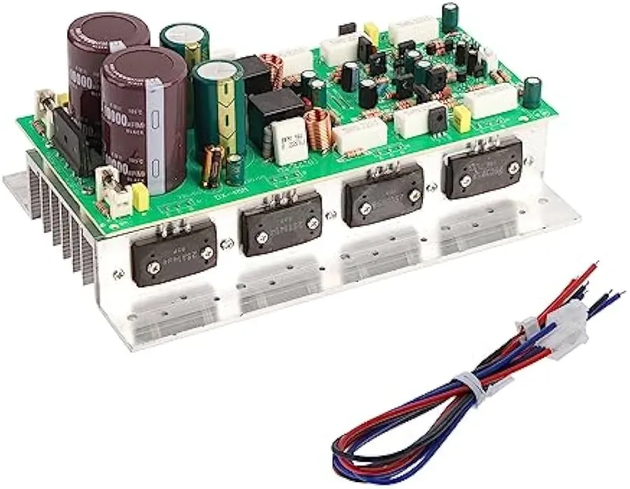
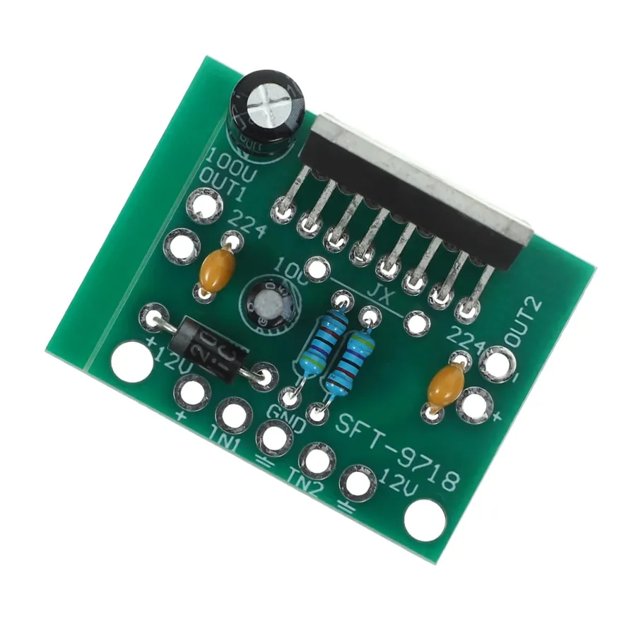
Key Components on an Amplifier Circuit Board
An amplifier circuit board's performance and functionality are dictated by the intricate interplay of its various components. These components work in concert to amplify electrical signals while maintaining signal integrity and stability. Understanding these fundamental building blocks is crucial for anyone working with or designing audio systems.
| Component | Function | Impact on Performance |
|---|---|---|
| Transistors (BJTs, MOSFETs) | Act as the active amplifying element, controlling current flow and achieving gain. | Primary determinant of amplification factor, output power, and efficiency. |
| Capacitors | Store electrical energy, used for coupling signals, filtering out noise, and stabilizing the power supply. | Critical for maintaining signal purity, frequency response, and power stability. |
| Resistors | Control current flow and voltage levels, establish biasing points, and limit signal levels. | Impact impedance, signal level, and thermal stability. |
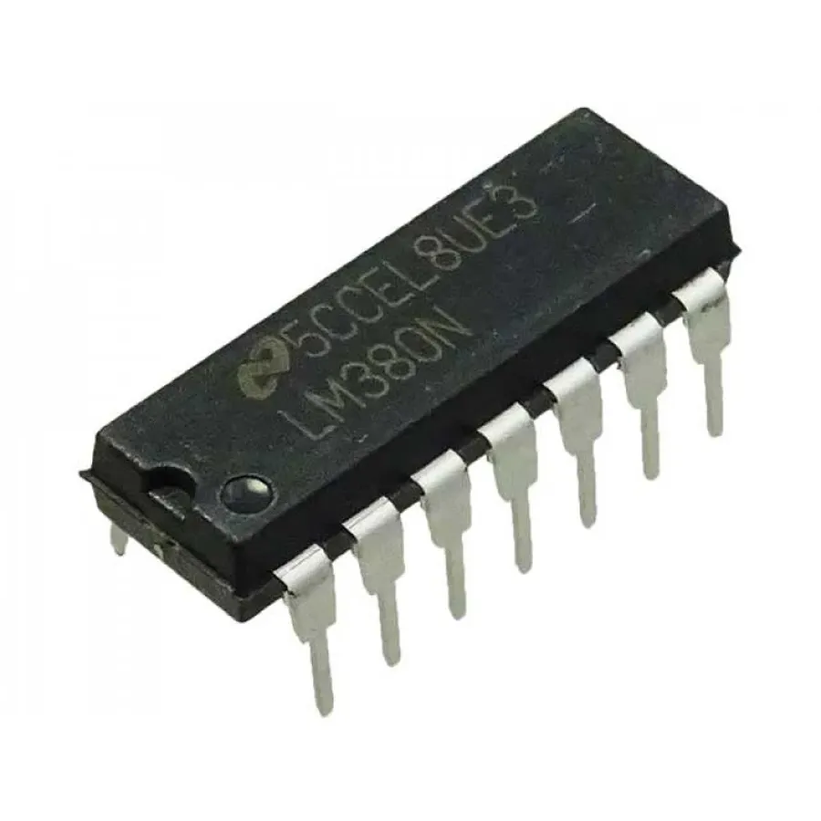
| Integrated Circuits (ICs) | Perform complex functions, such as operational amplifiers (op-amps), voltage regulators, and specialized audio processing. | Provide amplification, signal conditioning, and specific functions like filtering and tone control. |
| Inductors | Store energy in a magnetic field, used for filtering, impedance matching, and forming resonant circuits. | Important in high frequency circuits, power supplies, and for speaker impedance matching. |
| Diodes | Allow current to flow in one direction, commonly used for rectification and protection against reverse voltages. | Essential in power supplies and protection circuits. |
Choosing the Right Amplifier Circuit Board
Selecting the appropriate amplifier circuit board is crucial for optimal audio system performance. This decision hinges on understanding your specific needs, including power requirements, impedance matching, and desired channel configuration. A careful evaluation ensures the amplifier board will effectively drive your speakers or other audio transducers without distortion or damage.
| Factor | Consideration | Explanation |
|---|---|---|
| Power Requirements | RMS power output | Match the amplifier's power output to the power handling capabilities of your speakers. Overpowering can damage speakers; underpowering can lead to distortion. The amplifier's power output should be at least 20% higher than the speaker's continuous power handling capability. |
| Impedance | Speaker impedance in ohms | The impedance of the speakers must match the recommended impedance of the amplifier. Common impedances are 4, 8, and 16 ohms. Mismatched impedance can cause the amplifier to overheat, distort the audio signal, or potentially damage the amplifier or speakers. |
| Channel Configuration | Mono, Stereo, or Multi-channel | Determine the number of audio channels needed. Mono setups use a single channel, stereo uses two (left and right), and multi-channel systems are used in surround sound or complex audio setups. Consider the application - a single mono amplifier for a subwoofer versus a stereo amplifier for two speakers. Some applications may require a multi-channel setup to ensure each speaker has its own dedicated amplification. |
| Amplifier Class | Class A, Class B, Class AB, Class D | Each class has different efficiency and sound quality characteristics. Class A offers excellent linearity and sound but at low efficiency; Class B has higher efficiency but higher distortion; Class AB offers a good balance between them; Class D amplifiers are highly efficient. Choose an amplifier class based on the specific needs of the project and application. |
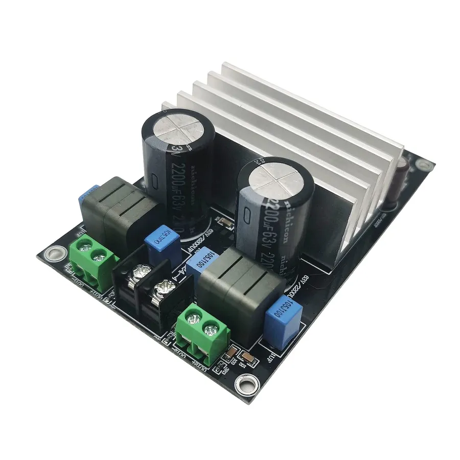
| Heat Dissipation | Heatsink and cooling | Consider the heat generated during operation. Make sure adequate heatsinking or other cooling mechanisms are provided to prevent overheating. |
| Total Harmonic Distortion (THD) | Lower THD for clearer audio | THD indicates how much unwanted harmonic distortion is added to the signal by the amplifier. A low THD is crucial for high fidelity audio applications. Select an amplifier with THD below 1%. |
| Frequency Response | Audio frequency range | The frequency response of the amplifier should cover the entire audio range that you plan to use (20Hz to 20kHz is standard for audible sound). |
| Power Supply | Voltage and current rating | Ensure the amplifier's power supply requirements align with the available power source. Note that power supply capacity determines maximum output power |
| Signal-to-Noise Ratio (SNR) | Higher SNR for quieter background | SNR indicates how clean the audio signal is compared to the noise floor. Higher SNR values are better. |
DIY Amplifier Circuit Board Projects
Embarking on a DIY amplifier circuit board project is a rewarding endeavor for electronics enthusiasts. This section provides a structured approach to building a basic amplifier, from understanding the necessary components to assembling and testing your creation. This hands-on experience will solidify your understanding of amplifier operation and circuit design.
Before beginning, it is critical to acknowledge that working with electrical circuits involves inherent risks. Always take necessary safety precautions. Ensure power sources are disconnected before working on circuits and understand the ratings of components to prevent damage and electrical shock.
Let's outline a basic project using common components, emphasizing clarity and ease of assembly:
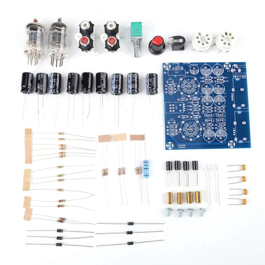
- Component Selection and Sourcing
Begin by sourcing the core components. For a basic Class AB amplifier, you'll typically require: transistors (e.g., NPN and PNP pairs like 2N3904/2N3906 or similar), resistors of various values (e.g., 100Ω, 1kΩ, 10kΩ), capacitors (e.g., electrolytic and ceramic types, like 10µF and 0.1µF), a potentiometer (for volume control), a suitable power source (e.g., a 9V battery or regulated power supply), and a breadboard or prototyping PCB. It's essential to select components based on your desired gain and impedance requirements. Check datasheets for component specifications. - Circuit Design and Schematic Interpretation
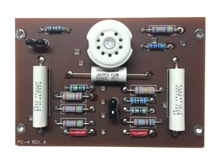
Refer to a basic Class AB amplifier schematic. Common designs are readily available online and in electronics textbooks. Understanding the schematic is vital, as it dictates component placement and connections. Note the roles of each component - transistors for amplification, resistors for current limiting and biasing, and capacitors for signal coupling and filtering. Take time to understand how current flows through the circuit. - Assembly on the Breadboard or PCB
Start assembly by placing the components on a breadboard (for prototyping) or a PCB. Begin by positioning transistors, then add resistors, and finally capacitors. Verify polarity of electrolytic capacitors. Use connecting wires to link the components according to the schematic. Precision and accuracy in this stage is critical for successful operation. Ensure all connections are secure and wires are not crossed or shorted. - Powering the Circuit and Initial Testing
Connect the power source to your amplifier circuit. A basic battery can be used for testing. Ensure the polarity is correct (positive to positive, negative to negative). Use a multimeter to measure voltages at various points in the circuit, verifying that your biasing is correct and that components are powered as expected. Do not connect an audio signal at this stage. Be alert for excessive current draw or unusual temperature increases in components, which indicate potential issues. - Audio Signal Input and Output Verification
Connect an audio source (e.g., phone, music player) to the input of your amplifier circuit, which has a potentiometer used to control gain. Connect a speaker or headphone to the output. Play some audio and observe if the output is amplified. Adjust the potentiometer to test the gain level. Use an oscilloscope to examine input and output waveforms, checking the signal's frequency, gain, and any distortion. - Troubleshooting and Refinement
Troubleshooting is an important step. If you experience no sound, check your connections. If the output is distorted, adjust biasing or component values. If the circuit overheats, check for short circuits or incorrect components. Use an oscilloscope to detect unwanted oscillations or noise. Make sure you understand the theory of operation, use the datasheet and modify the circuit only if you know what you are doing. Refinement of a DIY circuit is a trial and error process that often leads to a better final design.
Remember, patience is key in DIY electronics projects. This process will not only teach you the fundamental principles of audio amplification but also enhance your overall skills in electronics and circuit design.
Common Issues and Troubleshooting
Amplifier circuit boards, while essential for audio systems, are susceptible to various issues that can compromise their performance. Understanding these common problems and their corresponding troubleshooting techniques is crucial for both DIY enthusiasts and professionals. This section focuses on diagnosing and resolving typical issues such as signal distortion, overheating, and unwanted noise.
- Distortion
Distortion, characterized by a change in the output signal's waveform, often indicates overloading or a component failure. Possible causes include: Input signal level being too high, exceeding the amplifier's capacity; a damaged transistor or operational amplifier (op-amp); a faulty capacitor affecting signal coupling or filtering; or incorrect biasing of transistors. To troubleshoot, start by reducing the input signal level and check the supply voltage. Check each component based on the circuit design with a multi meter. - Overheating
Excessive heat generation is a common problem, especially in power amplifier stages. Potential causes include: Inadequate heat sink for power components; operating the amplifier beyond its rated power output; short circuits or component failures causing excessive current draw. To mitigate this, ensure that heat sinks are properly installed and of sufficient size. It is also important to verify the design specification. Replace any damaged components. - Noise
Unwanted noise, such as hum, hiss, or static, can significantly degrade audio quality. Noise sources include: Poor grounding leading to ground loops; electromagnetic interference (EMI) from external devices or power supplies; defective capacitors in the signal path or power supply; or a poorly designed amplifier circuit. Start by verifying that all connections are secure and that the ground path is correct. Consider using shielded cables to minimize EMI. Replace suspect capacitors. Check the circuit design and correct issues. - Reduced Output Power
If the amplifier isn't producing the expected output power, investigate potential problems such as low supply voltage, faulty components in the output stage, incorrect biasing, or impedance mismatch. Check the power supply, replace suspect components and verify the output power of the amplifier with a test signal. - Intermittent Operation
Intermittent issues can be frustrating to diagnose and may arise from loose connections, cracked solder joints, or temperature-sensitive components. Inspect all connections and resolder if necessary. Pay close attention to heat-sensitive components.
Frequently Asked Questions About Amplifier Circuit Boards
This section addresses common queries regarding amplifier circuit boards, offering clear and concise answers to help users better understand their function, selection, and application.
- What is the primary function of an amplifier circuit board?
An amplifier circuit board's core function is to increase the power of an electrical signal. This is achieved by taking a weak input signal and boosting its amplitude, thereby making it suitable to drive a load, such as a speaker. The board facilitates both voltage and current gain, depending on the circuit design. - What exactly constitutes an amplifier circuit?
An amplifier circuit is a specific configuration of electronic components (such as transistors, resistors, and capacitors) designed to increase the power of an electrical signal. This is not just one component, but rather an interconnected network strategically assembled on the amplifier circuit board to achieve signal amplification. The design is crucial for determining the amplifier’s performance characteristics. - How do I choose the right amplifier board for my needs?
Selecting the appropriate amplifier board involves considering several key factors. First, determine your power requirements based on the load (e.g., speakers). Next, match the impedance of your load with the amplifier's output impedance to avoid mismatch issues. Finally, evaluate the number of channels (mono, stereo, multi-channel) that your application requires. Also, consider the amplifier class (A, B, AB, or D) based on the balance between audio quality and efficiency. - How many watts can a 3055 amplifier board typically handle?
The power output of a board using the 3055 transistor depends heavily on the specific circuit design and the cooling system incorporated. The 2N3055 transistor itself has a power dissipation rating, but the overall amplifier circuit will limit the actual power output. Typically, a single 2N3055 transistor is often used in amplifier stages that can range from a few watts up to perhaps 50 watts, but not without a heat sink. Multiple transistors in parallel configurations are used for increased power output. Thus, a 3055 amp board does not have a singular specific wattage output. - What are the common problems one might encounter with amplifier circuit boards?
Common issues include distortion, which may indicate signal clipping or component failure, overheating due to insufficient heat dissipation or overdriving, and noise or hum stemming from grounding problems or component malfunctions. These issues can be diagnosed using a multimeter to verify the power supply, and an oscilloscope to investigate the signal chain. - Can I build my own amplifier circuit board, and what skills would it require?
Yes, building your own amplifier circuit board is feasible with basic soldering and electronics skills. It requires the ability to read schematic diagrams, identify electronic components, properly assemble those components on the board, and basic fault-finding methods. A fundamental understanding of electrical circuits is necessary. It's advisable to start with simpler designs before moving to complex projects. - What are the advantages of different amplifier circuit board types (Class A, B, AB, D)?
Class A amplifiers offer the best audio quality due to their linear operation but are very inefficient. Class B amplifiers provide high efficiency but can suffer from crossover distortion, which is mitigated by the design of Class AB amplifiers that offer a compromise between the two. Class D amplifiers offer extremely high efficiency and are used in high-power applications. The selection depends on the desired balance between audio quality and power efficiency.
Advanced Topics: High Power and Wireless Integration

High-power amplifier circuit board design and wireless integration represent the cutting edge of audio amplification technology, catering to applications that demand substantial output power, seamless connectivity, or both. These advanced concepts go beyond basic amplification, involving complex thermal management, efficient power delivery, and sophisticated signal processing to achieve desired performance and reliability.
High-power amplifier design focuses on delivering substantial audio output without distortion or excessive heat generation, necessitating advanced techniques to manage power efficiency and thermal loads. Simultaneously, wireless integration, primarily through technologies like Bluetooth and WiFi, enables greater versatility and connectivity for audio systems, opening up new avenues for control, audio streaming and synchronization.
Future trends in amplifier technology are pushing the boundaries further, exploring miniaturization, higher energy efficiency, and integration of advanced digital signal processing (DSP) to provide enhanced audio fidelity and control. Below is a more detailed look at these advanced amplifier technologies:
- High-Power Amplifier Design
Focuses on maximizing output power while minimizing distortion and thermal issues. This often involves the use of advanced transistors, specialized cooling systems, and optimized circuit layouts. High power designs require efficient heat dissipation strategies to prevent damage or performance degradation due to thermal runaway. Efficient power supply designs, including switch-mode power supplies, are commonly employed to deliver the necessary current and voltage. - Wireless Integration (Bluetooth and WiFi)
The integration of wireless technologies like Bluetooth and WiFi adds significant flexibility to amplifier circuit boards. Bluetooth allows for direct audio streaming from mobile devices and other peripherals, while WiFi enables network-based audio streaming and control. These wireless technologies require additional RF circuitry, antennas, and digital processing capabilities to ensure reliable and low-latency connections. - Future Trends
The future of amplifier design points towards greater miniaturization, improved energy efficiency, and the enhanced integration of Digital Signal Processing (DSP). DSP allows for real-time adjustments to audio parameters, noise cancellation, equalization, and other signal enhancements. Class D amplifiers are increasingly prevalent due to their efficiency, and are anticipated to continue this trend in both high power and low power applications. Additionally, new materials and component technologies are being explored to further improve amplifier performance and reliability.
In conclusion, the amplifier circuit board is the foundational building block of all audio amplification systems. From the smallest portable speakers to the most complex sound systems, these boards play a vital role in shaping our soundscape. Understanding their functions, types, and components empowers both casual listeners and DIY enthusiasts to engage with the technology on a more profound level. Whether you're looking to buy, or build your own amplifier circuit board, the possibilities are endless. The future of amplifier technology, with its focus on higher efficiency and seamless wireless integration, promises even more exciting developments, furthering the amplification of our audio experiences.