Understanding Circuit Boards: A Comprehensive Guide
From smartphones to satellites, circuit boards are the unsung heroes of the modern electronic age. These seemingly simple platforms are the bedrock upon which complex technologies are built. This article will illuminate the essential aspects of circuit boards, from their basic function to their intricate manufacturing processes, providing you with a comprehensive understanding of these vital components and the role they play in our daily lives.
What is a Circuit Board?
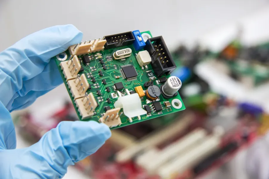
A circuit board, most commonly known as a printed circuit board (PCB), serves as the foundational platform for electronic devices. It is essentially a non-conductive substrate meticulously designed with conductive pathways, referred to as traces, that electrically interconnect electronic components. This crucial structure not only physically supports components but also facilitates the flow of electrical signals necessary for the device's operation, making it indispensable to modern electronics.
Types of Circuit Boards: A Detailed Overview
Circuit boards, also known as PCBs, come in a variety of types, each tailored to specific applications and performance requirements. Understanding these types is crucial for selecting the optimal board for your electronic design. This section provides a detailed overview of common PCB types, their characteristics, and their relative advantages and disadvantages.
| Type | Description | Applications | Advantages | Disadvantages |
|---|---|---|---|---|
| Single-Layer PCB | A PCB with conductive material on one side. | Simple electronic devices, low-density circuits, educational projects. | Lowest cost, simple design and manufacture, suitable for beginners. | Limited complexity, not suitable for high-density applications, susceptible to noise. |
| Double-Layer PCB | A PCB with conductive material on both sides. | Intermediate complexity electronics, power supplies, small appliances. | Increased component density compared to single layer, versatile for moderate complexity, cost effective. | More expensive than single-layer boards, not optimal for high-density circuits. |
| Multi-Layer PCB | A PCB with three or more layers of conductive material. | High-density and complex electronics such as computers, smartphones, medical equipment. | Very high density, allows complex routing, supports sophisticated functions, superior signal integrity. | Highest cost, requires complex manufacturing process, more difficult to troubleshoot. |
| Rigid PCB | A PCB made from a solid, non-flexible material such as FR-4. | Majority of electronic devices; computers, industrial control systems, consumer electronics. | Durable, reliable, well-established technology, various design options, relatively easy to manufacture. | Not suitable for bending or flexing, limited adaptability to complex shapes. |
| Flexible PCB | A PCB made from flexible materials such as polyimide. | Wearable electronics, automotive applications, medical devices, aerospace applications. | Highly flexible, lightweight, space-saving, allows for intricate shapes, excellent bend radius. | More expensive than rigid boards, more sensitive to environmental factors, less robust. |
| Rigid-Flex PCB | A hybrid PCB that combines rigid and flexible sections. | Advanced applications requiring flexibility and reliability in a small footprint, specialized devices. | Combines the advantages of both rigid and flexible boards, allows for complex designs. | Most complex and costly type of PCB, requires specialized manufacturing and assembly. |
Key Components on a Circuit Board
A circuit board's functionality stems from the synergistic interaction of numerous electronic components. These components, each with distinct roles, collectively enable the board to perform its intended function. Understanding these basic building blocks is crucial to grasping how circuit boards operate.
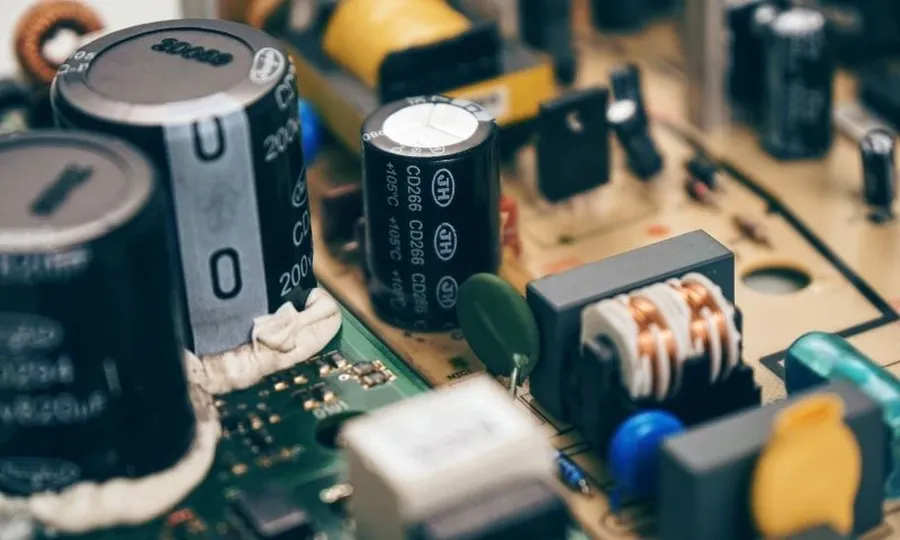
- Resistors
Resistors impede the flow of electrical current, controlling the voltage and current levels within a circuit. They are critical for setting proper operating conditions for other components and preventing damage from excessive current. - Capacitors
Capacitors store electrical energy in an electric field. They are used for filtering, smoothing power supply lines, and timing circuits. Their ability to charge and discharge makes them invaluable in many electronic functions. - Inductors
Inductors store energy in a magnetic field when current flows through them. They are used for filtering, signal processing, and energy storage, particularly in power supplies and radio frequency circuits. - Transistors
Transistors are semiconductor devices used to amplify or switch electronic signals and electrical power. They are the fundamental building blocks of modern electronics, enabling complex functions in a myriad of devices. - Diodes
Diodes are semiconductor devices that allow current to flow primarily in one direction. They are crucial for rectification, signal modulation, and protection against reverse currents. - Integrated Circuits (ICs)
ICs, also known as microchips, integrate numerous transistors, resistors, and other components onto a single semiconductor substrate. They perform a variety of complex functions and are critical for modern electronics, including microprocessors, memory chips, and application-specific ICs (ASICs).
| Component | Function | Typical Application |
|---|---|---|
| Resistor | Impedes current flow | Current limiting, voltage division |
| Capacitor | Stores electrical energy | Filtering, decoupling, timing |
| Inductor | Stores energy in a magnetic field | Filtering, signal processing, energy storage |
| Transistor | Amplifies or switches electronic signals | Amplification, switching, logic gates |
| Diode | Allows current flow in one direction | Rectification, signal modulation |
| Integrated Circuit | Performs complex functions | Microprocessors, memory, logic |
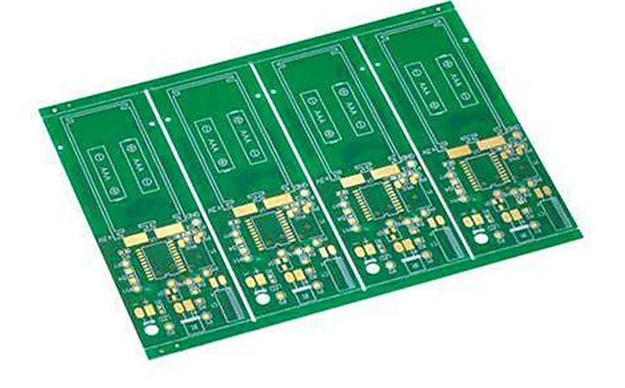
The Circuit Board Manufacturing Process: A Step-by-Step Guide
The manufacturing of a circuit board, or printed circuit board (PCB), is a multi-stage process requiring precision and adherence to strict specifications. This section details each critical phase, from initial design to final assembly, providing a comprehensive overview of the complexities involved in producing a functional PCB.
- Design and Layout
The process starts with the design phase, where engineers use specialized software (e.g., Altium Designer, Eagle) to create a schematic of the desired circuit. This schematic is then converted into a physical layout of the PCB, specifying component placement and routing of conductive traces. This stage often involves iterative design reviews to ensure functionality and manufacturability. - Prototyping
Before mass production, a prototype PCB is fabricated. This step involves transferring the design layout to a copper-clad laminate, and is critical for testing and validation of the design. Adjustments are frequently made at this stage to optimize performance or address unforeseen issues. Prototypes are often manufactured using quicker, less costly methods, focusing on functionality over high-volume production efficiency. - Etching
Once the prototype is validated or design finalized, the PCB is prepared for mass production. The copper-clad laminate is first covered with a photoresist layer, then exposed to UV light through a mask containing the circuit pattern. The unexposed photoresist is then washed away, and the exposed copper is etched using chemical solutions. This process removes unwanted copper, leaving behind the desired circuit traces and pads. - Drilling
After etching, the PCB undergoes a drilling process to create holes for component leads and vias for layer-to-layer electrical connections. High-precision computer-controlled drilling machines are used to ensure accurate hole placement and diameters as specified by the design. - Plating
Following drilling, the PCB undergoes a plating process. This involves applying a thin layer of conductive material, typically copper, to the holes and the exposed copper traces. This ensures good conductivity and enhances solderability. The plating process may involve multiple layers of different metals to enhance electrical performance and longevity. Often gold or tin finishes are applied for additional reliability. - Solder Mask Application
After plating, a solder mask is applied to the PCB. This layer is a thin protective coating, typically green or blue, applied to all areas except those where components will be soldered. The solder mask prevents accidental solder bridging and ensures accurate soldering during assembly. - Silkscreen Printing
The final stage before assembly includes silkscreen printing, where labels, reference designators, logos, and other identifying markings are printed onto the board, usually using white ink. This aids in component placement and troubleshooting. - Component Assembly
Components are placed onto the board, a process which is completed with automated pick-and-place machines or manual assembly. The components are then soldered to the board using techniques such as reflow soldering or wave soldering. - Testing and Inspection
After assembly, the boards are thoroughly tested and inspected. Various testing methods such as In-Circuit Testing (ICT), Automated Optical Inspection (AOI), and functional testing are used to identify any defects in the board or assembly and ensure the PCB functions as designed.
Materials Used in Circuit Board Fabrication
The selection of materials for circuit board fabrication is a critical decision that directly impacts the board's performance, durability, and cost. Various materials, each with unique properties, are employed to meet diverse application requirements. This section delves into commonly used materials, including FR-4, aluminum, and polyimide, and examines their specific characteristics and applications.
| Material | Description | Key Properties | Typical Applications | Advantages | Disadvantages |
|---|---|---|---|---|---|
| FR-4 | A composite material consisting of woven fiberglass cloth with an epoxy resin binder. The most common substrate used in PCBs. | Good electrical insulation, high strength-to-weight ratio, flame retardant, low cost. | General purpose PCBs for consumer electronics, computer motherboards, and industrial control systems. | Cost-effective, easy to manufacture, good mechanical strength. | Not suitable for high-temperature applications, can be brittle. |
| Aluminum | A metal substrate, typically with a thin dielectric layer. It provides excellent thermal conductivity and mechanical stability. | High thermal conductivity, good mechanical strength, lightweight. | LED lighting, power electronics, automotive electronics. | Excellent heat dissipation, good shielding, durable. | Higher cost than FR-4, can be difficult to form complex shapes. |
| Polyimide | A high-performance polymer known for its excellent thermal and chemical resistance. | High thermal resistance, excellent flexibility, chemical resistance, good electrical insulation | Flexible circuits, high-temperature electronics, aerospace applications, medical devices. | High flexibility, excellent temperature stability, chemical resistance. | Higher cost, can be more challenging to process. |
| Teflon (PTFE) | A fluoropolymer known for its exceptional electrical properties. | Very low dielectric constant and loss tangent, high temperature resistance. | High-frequency circuits, microwave applications, aerospace. | Excellent electrical properties, low loss, high-temperature stability. | Expensive, difficult to process. |
Circuit Board Design Considerations
Effective circuit board design is paramount for ensuring both functionality and manufacturability. This involves meticulous planning and attention to detail across various aspects, from component placement to thermal management. These considerations are not merely about getting the circuit to work, but also about optimizing its performance, reliability, and cost-effectiveness.
- Component Placement:
Strategic placement of components is crucial for minimizing signal interference and optimizing trace routing. Consider the proximity of heat-generating components and the flow of current through the board. Components should be placed in a manner that minimizes the physical length of the current path, thereby reducing resistance and signal degradation. - Trace Routing:
The path of conductive traces must be carefully planned to ensure signal integrity. Traces should be short, direct, and of appropriate width to carry the intended current. The use of ground planes and differential pairs is essential for minimizing noise and interference, ensuring the clean transmission of signals. - Signal Integrity:
Maintaining signal integrity ensures that electrical signals travel through the circuit board with minimal distortion or loss. This involves controlling impedance, minimizing reflections, and managing crosstalk between traces. Proper design of impedance matching networks and termination circuits is critical for high-speed signals. - Thermal Management:
Effective thermal management prevents overheating of components, which can lead to performance degradation and reduced lifespan. This includes using thermal vias, heatsinks, and strategic component placement to dissipate heat efficiently. The selection of board materials with good thermal conductivity can also improve heat dissipation. - Design for Manufacturability (DFM):
A design that is easy to manufacture not only reduces cost but also ensures consistency. This entails adhering to manufacturing guidelines, such as clearances for soldering and drilling, use of fiducial markers, and panelization for efficient production. DFM principles help minimize manufacturing errors and optimize assembly processes.
Frequently Asked Questions About Circuit Boards
This section addresses common queries about circuit boards, providing clear and concise answers to help users understand their function, types, and troubleshooting. We will clarify the distinctions between similar components, such as motherboards and circuit boards, explore cost considerations, and give guidance on identifying defective boards.
- What is the key difference between a motherboard and a circuit board?
While both are types of circuit boards, a motherboard is a complex main circuit board in a computer or electronic system, housing core components like the CPU, RAM, and expansion slots. A circuit board (PCB) is a broader term referring to any board that supports and connects electronic components. Think of a motherboard as a highly integrated and specialized type of circuit board within a larger system. - What is the average cost of a circuit board?
The cost of a circuit board varies widely based on several factors, including its complexity (number of layers), size, materials used, and manufacturing volume. Simple, single-layer PCBs can be very inexpensive, while complex, multi-layer boards with advanced materials can cost significantly more. Small batches tend to have higher per-unit costs than mass production runs. - What are the common types of circuit boards?
Circuit boards are generally classified by their physical structure and the number of conductive layers. Common types include single-layer PCBs, which have conductive traces on one side, double-layer PCBs with traces on both sides, and multi-layer PCBs, which consist of three or more conductive layers. Additionally, there are rigid PCBs, flexible PCBs, and rigid-flex PCBs, each with distinct applications. Each type presents unique trade-offs in cost, complexity, and suitability for different applications. - How can I tell if a circuit board is defective?
Identifying a bad circuit board can sometimes be challenging. Common signs include visible damage such as burnt components, cracked traces, or corrosion. Malfunctioning components may also be the problem, leading to operational issues in the device. You can use a multimeter to check for continuity and voltage. In some cases, specialized testing equipment might be required to pinpoint the fault. When diagnosing issues, it is crucial to take the correct safety measures to prevent personal injury and further damage to the circuit board. - What is the significance of the material used in a circuit board?
The materials used to fabricate a circuit board significantly impact its performance, durability, and cost. For instance, FR-4 is a widely used material known for its cost-effectiveness and good electrical properties, whereas materials like aluminum are preferred for thermal management. High-frequency applications might call for materials with low dielectric loss, like polyimide. The selection of material is a critical aspect of the design process. - Can I repair a damaged circuit board myself?
Repairing circuit boards requires specialized tools and skills, including soldering equipment, a multimeter, and knowledge of electronics. Minor repairs, such as replacing a discrete component, can be attempted by experienced users. However, complex repairs are best left to trained professionals to avoid further damage. Before attempting any repair, ensure that the circuit board is isolated from its power source and take appropriate safety measures.
The Future of Circuit Board Technology
The circuit board industry is undergoing rapid evolution, driven by advancements in materials, design methodologies, and manufacturing techniques. These innovations are pushing the boundaries of what's possible in electronics, enabling smaller, more powerful, and more versatile devices across various industries.
The future of circuit board technology is characterized by several key trends:
- Advanced Materials
Research is heavily focused on developing new materials that offer superior electrical, thermal, and mechanical properties. This includes exploring novel polymers, ceramics, and composites that can handle higher frequencies, greater power densities, and more extreme environments. Examples are low-loss dielectrics for high-speed data transfer and thermally conductive substrates for efficient heat dissipation. - Flexible and Stretchable Electronics
There is a growing demand for circuit boards that can conform to curved or flexible surfaces. Flexible and stretchable PCBs are being developed using materials like polyimide and liquid crystal polymers. These are poised to revolutionize applications in wearable devices, flexible displays, and implantable medical devices. This technology enables electronics to be seamlessly integrated into non-planar surfaces. - 3D Printed Circuit Boards
Additive manufacturing techniques, such as 3D printing, are emerging as a viable method for creating circuit boards. This technology allows for the rapid prototyping of complex circuit designs and enables customization without the need for traditional etching and drilling. 3D printing opens up new possibilities for creating intricate geometries and integrating mechanical structures directly into the circuit board. - Miniaturization and High-Density Interconnect (HDI)
The push for smaller and more densely packed electronic devices is driving the development of HDI technologies. These techniques enable finer traces and smaller vias, leading to more compact and powerful circuit boards. HDI also facilitates the integration of more components within the same footprint. This is critical for applications such as smartphones, tablets, and other portable electronics. - Embedded Passives and System-in-Package (SiP)
Embedding passive components like resistors and capacitors directly within the PCB layers is gaining traction. This technology helps to reduce the overall size of the circuit board and improve performance. Additionally, System-in-Package (SiP) integration combines multiple integrated circuits and other components within a single package. This approach allows for greater functionality in smaller spaces. - Advanced Manufacturing Techniques
New manufacturing techniques such as laser direct structuring (LDS) and advanced plating methods are improving precision and enabling the production of increasingly intricate designs. These methods offer high levels of accuracy and are more efficient than traditional approaches, enhancing both the performance and reliability of circuit boards.
These trends are impacting diverse industries:
- Consumer Electronics
Miniaturization and enhanced performance will enable more powerful and compact smartphones, wearables, and other consumer devices. - Medical Devices
Flexible and biocompatible circuit boards will advance implantable medical devices and wearable health monitors. - Aerospace and Automotive
High-reliability and temperature-resistant circuit boards will be essential for advanced aerospace systems and electric vehicles. - Industrial Automation
Rugged and robust circuit boards will support the increasing adoption of automation in manufacturing and other industrial settings. - Internet of Things (IoT)
Low-power and small-form-factor PCBs will facilitate the proliferation of connected devices.
Circuit boards are essential for modern electronics, acting as the foundational building blocks for countless devices. From understanding the various types of boards to appreciating the complexities of the manufacturing process, it's evident that circuit board technology is constantly evolving, promising even more innovative solutions in the future. This article provides a comprehensive overview, aiming to equip readers with the knowledge to navigate the world of PCBs and appreciate the vital role they play in our technological landscape. As technology continues to advance, the importance of the circuit board will only continue to grow.