Understanding Electronic Circuit Boards: From Basics to Advanced Applications
From the smartphones in our pockets to the complex machinery that powers modern life, the electronic circuit board is the unsung hero driving technological advancements. These seemingly simple boards are the foundation upon which all electronic devices are built, connecting components and enabling the flow of electricity. In this article, we'll demystify the electronic circuit board, exploring its components, types, and crucial role in our daily lives. We will journey through its intricate designs and practical applications.
What is an Electronic Circuit Board?
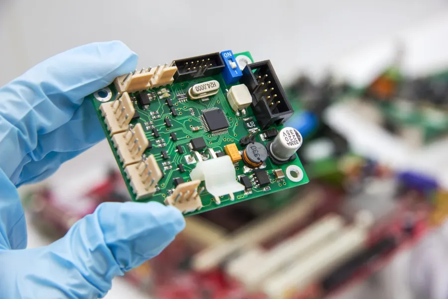
An electronic circuit board, commonly known as a Printed Circuit Board (PCB), serves as the foundational platform for assembling and connecting electronic components. It provides both the mechanical support and the electrical pathways required for these components to function as a cohesive electronic system. Essentially, a PCB is the backbone of nearly every modern electronic device, facilitating the flow of electricity and signals between diverse components such as resistors, capacitors, and integrated circuits.
Key Components of an Electronic Circuit Board
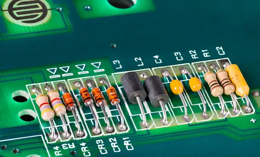
Electronic circuit boards, the bedrock of modern electronics, rely on a variety of components to perform their intended functions. These components, working in concert, facilitate the control and manipulation of electrical signals, ultimately enabling complex electronic systems to operate. The following will outline some of the key components and their role.
| Component | Function | Symbol |
|---|---|---|
| Resistor | Limits or regulates the flow of electrical current. | A zig-zag line |
| Capacitor | Stores electrical energy in an electric field; blocks DC while allowing AC to pass. | Two parallel lines |
| Diode | Allows current to flow in one direction while blocking it in the opposite direction. | A triangle pointing to a line |
| Transistor | Amplifies or switches electronic signals and electrical power. | A line with three points connected to it |
| Inductor | Stores energy in a magnetic field; resists changes in current. | A coil shape |
| Integrated Circuit (IC) | A miniaturized electronic circuit consisting of numerous interconnected components within a single package. | A rectangle with many connections |
| Connectors | Facilitate physical and electrical connections to external devices or systems. | Varies based on connector type. |
These components are fundamental building blocks, and their collective operation dictates the circuit board's overall performance and functionality. The specific combination and configuration of these components are carefully chosen based on the intended function of the electronic device or system.
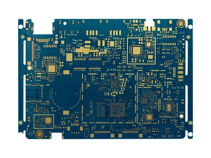
Types of Electronic Circuit Boards
Electronic circuit boards, also known as printed circuit boards (PCBs), are not monolithic; they come in various types, each tailored to specific applications and performance requirements. The selection of the correct type of PCB is critical for a successful product design, affecting performance, cost, and reliability. This section explores the most common types of PCBs, their characteristics, and their suitability for various uses.
| PCB Type | Description | Applications | Advantages | Disadvantages |
|---|---|---|---|---|
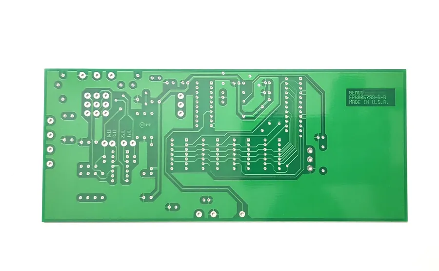
| Single-Sided PCB | Components and conductive traces are on one side of the substrate. | Simple electronic devices, toys, LED lighting. | Low cost, easy to manufacture. | Limited complexity, not suitable for high-density circuits. |
| Double-Sided PCB | Components and traces on both sides of the substrate with vias connecting layers. | Consumer electronics, basic industrial controls. | Increased circuit density, more versatile than single-sided. | More complex and expensive than single-sided PCBs. |
| Multi-Layer PCB | Three or more layers of conductive traces, separated by insulating layers. | Advanced electronics, computers, high-speed communications. | High density, complex routing, excellent performance. | Higher cost, complex manufacturing process. |
| Flexible (Flex) PCB | Thin, flexible substrate that can bend and conform to complex shapes. | Wearable electronics, medical devices, automotive applications. | Lightweight, flexible, durable, good for dynamic applications. | Higher cost, sensitive to mechanical stress, limited component mounting. |
| Rigid-Flex PCB | Combines rigid and flexible sections to offer both component mounting and flexible interconnection. | Aerospace, high-end electronics, robotic systems. | Combines flexibility and rigidity, saves space. | Complex manufacturing, high cost. |
| Metal Core PCB | Utilizes a metal substrate for improved heat dissipation. | High-power LEDs, power converters, automotive electronics. | Excellent thermal management, robust mechanical stability. | Higher weight, less flexible, more expensive than traditional PCBs. |
How Electronic Circuit Boards Work
Electronic circuit boards, or PCBs, serve as the central nervous system of electronic devices, facilitating the controlled flow of electrical signals and power. They provide both a mechanical foundation for mounting components and the electrical pathways necessary for those components to interact and perform complex functions.
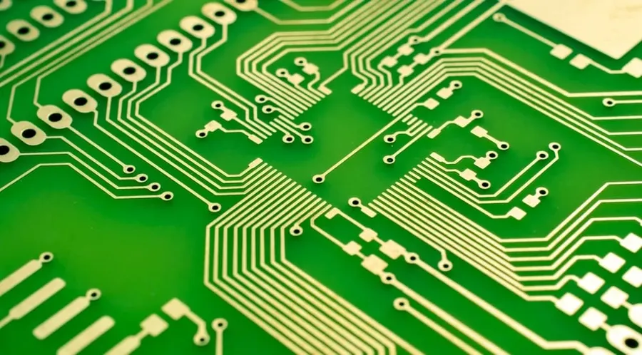
At its core, a PCB operates through a network of conductive traces—typically made of copper—that are etched onto an insulating substrate. These traces act as wires, connecting different components such as resistors, capacitors, and integrated circuits. When electrical power is applied to the board, electrons flow through these traces, creating circuits that enable the desired functions of the electronic device. The design of these traces is carefully planned to ensure proper signal integrity and minimize interference.
The interaction of electrical components is precisely orchestrated by the design of the PCB layout. Each component is strategically placed and connected to the appropriate traces, allowing for the accurate distribution of voltage and current. This organized approach ensures that complex electronic designs can function predictably and reliably. The substrate material also plays a crucial role, providing a stable and non-conductive platform that protects against shorts and facilitates thermal management.
The Manufacturing Process of PCBs
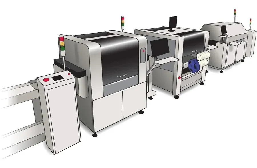
The fabrication of electronic circuit boards, commonly known as PCBs, is a multi-stage process that transforms design specifications into a functional component. This intricate process involves precision engineering, advanced chemical techniques, and meticulous quality control to ensure each board meets stringent performance criteria. Key steps include design, etching, drilling, plating, and assembly, each contributing to the final product's reliability and functionality. Advances in manufacturing techniques have continually improved board precision, complexity, and cost-effectiveness.
- Design
The process begins with the electronic design, typically using specialized software, resulting in a digital blueprint of the PCB, detailing the layout of components and conductive traces. This design stage is critical for defining the board's functionality and ensuring signal integrity. - Printing
The design is then transferred to a physical substrate, typically a copper-clad laminate, using a specialized printing process. This involves either photo-printing for precise patterns or screen-printing for larger conductive areas. The printed design acts as a guide for the subsequent etching process. - Etching
In this step, the unprotected copper is removed from the laminate. The areas covered by the printed design resist the etching process, leaving behind the conductive traces and pads that will form the electrical connections. Chemical solutions are used to dissolve away the unwanted copper. - Drilling
Precisely sized holes are drilled into the PCB at locations specified by the design for mounting component leads and vias (vertical electrical connections between layers). This stage requires high precision machinery to ensure accurate hole alignment and size. - Plating
After drilling, the holes and copper traces are plated with conductive materials, such as copper, tin, or gold. This process strengthens the electrical connections, prevents corrosion and enables reliable soldering. - Solder Mask Application
A solder mask is applied to the board, leaving only the pads that need to be soldered exposed. This protects the board from oxidation, prevents solder bridges between pads and ensures solder is precisely applied. - Silkscreen Printing
Silkscreen printing is often used to print identifying information on the board, such as component designators, logos, and other relevant information for assembly and troubleshooting. This helps with assembly and future servicing. - Assembly
The final step involves mounting the electrical components onto the PCB using surface mount technology (SMT) and through-hole technology. Automated machines are generally employed in this stage to place and solder components. - Testing
The completed PCB undergoes rigorous electrical testing to ensure the circuits function as per design, ensuring that there are no short circuits, open circuits, or incorrect component placements. This may involve continuity checks, functional tests and automated optical inspection.
PCB Design Fundamentals
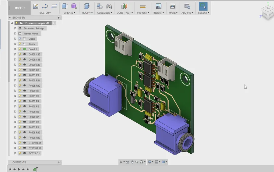
Effective Printed Circuit Board (PCB) design is crucial for the functionality and reliability of electronic devices. It encompasses several fundamental principles, including schematic capture, layout, and routing, each playing a vital role in the final performance of the circuit. A well-executed PCB design also addresses essential considerations such as signal integrity, thermal management, and mitigation of electromagnetic interference (EMI).
The PCB design process starts with capturing the circuit's electrical connections via a schematic diagram. This representation visually documents the components and their interactions, typically using computer-aided design (CAD) software. Then, the layout phase deals with the physical arrangement of these components on the board. Routing, the last major step, creates the conductive pathways, known as traces, to establish electrical connections between the components according to the schematic. Successful PCB design requires careful planning and attention to detail, particularly regarding signal integrity, thermal management and electromagnetic interference.
- Schematic Capture
Creating a digital representation of the circuit using CAD software. This includes selecting components from libraries and correctly interconnecting them. - Layout
The physical placement of components on the PCB, balancing functionality with manufacturing considerations. Component placement affects signal paths and thermal performance. - Routing
Creating the traces that connect components. This involves choosing the path, layer, and width of the traces to ensure signal integrity and reliable electrical connections.
| Design Consideration | Description | Impact |
|---|---|---|
| Signal Integrity | Maintaining signal quality by minimizing reflections, crosstalk, and impedance mismatches. | Ensures accurate and reliable data transfer, avoids signal loss and corruption. |
| Thermal Management | Managing heat generated by components to prevent overheating. | Prevents component failure, improves reliability and increases the lifespan of the device. |
| Electromagnetic Interference (EMI) | Reducing unwanted electromagnetic radiation that can interfere with other electronics. | Minimizes unwanted noise, ensures the device meets regulatory compliance standards and avoids performance degradation |
Resources for learning PCB design include online courses, tutorials, and educational books. Many CAD software packages offer tutorials and documentation. Open-source software options also provide avenues to explore and experiment with PCB design principles and techniques. A strong foundation in electrical engineering principles is highly beneficial for advanced PCB design.
Applications of Electronic Circuit Boards
Electronic circuit boards, also known as PCBs (Printed Circuit Boards), are the foundational building blocks of nearly all modern electronic devices, enabling connectivity and functionality across a diverse spectrum of applications. Their versatility stems from the ability to accommodate a wide array of components and configurations, tailored to meet the specific demands of various industries.
- Consumer Electronics
PCBs are ubiquitous in everyday consumer electronics such as smartphones, tablets, laptops, and televisions. They form the core of these devices, managing complex functionalities from processing and display to communication and power management. The constant drive for miniaturization and increased performance fuels continuous innovation in PCB design and manufacturing for this sector. - Automotive Industry
The automotive industry is increasingly reliant on PCBs for control systems, engine management, navigation, and infotainment systems. PCBs are vital for advanced driver-assistance systems (ADAS), electric vehicle (EV) battery management, and autonomous driving technologies. The stringent requirements for reliability and durability under harsh environmental conditions make this a challenging but crucial area for PCB applications. - Medical Devices
Medical devices, ranging from diagnostic equipment to therapeutic instruments, employ PCBs for precise control and data acquisition. They are essential in imaging systems, patient monitoring devices, and implantable medical technologies. The stringent regulatory requirements and the need for high reliability and safety are paramount in PCB design for medical applications. - Aerospace and Defense
In aerospace and defense applications, PCBs withstand extreme environmental conditions, handling critical functions in avionics, satellite communication, and missile guidance systems. High reliability, performance, and resistance to vibration, temperature extremes, and radiation are essential design considerations for PCBs in this field. These advanced PCBs often require specialized materials and manufacturing techniques. - Industrial Control Systems
Industrial control systems employ PCBs for process automation, robotics, and manufacturing equipment management. These robust PCBs withstand harsh environments and maintain high reliability and precision in operations. PCBs in this sector often feature ruggedized designs and enhanced durability, capable of operating reliably in challenging conditions.
The future of PCBs is characterized by trends towards increased miniaturization, higher circuit density, and improved thermal management. The development of flexible and stretchable PCBs will broaden the applications into wearable devices and advanced sensing technology. Furthermore, the integration of novel materials and additive manufacturing techniques promises to revolutionize PCB design and production, leading to more versatile, efficient, and sustainable electronic systems.
Frequently Asked Questions About Electronic Circuit Boards
This section addresses common inquiries about electronic circuit boards, providing clear and concise answers to help you better understand these fundamental components of modern electronics.
- What exactly is a circuit board in electronics?
An electronic circuit board, also known as a printed circuit board (PCB), serves as a foundational platform for mounting and connecting electronic components. It provides both mechanical support and electrical pathways (traces) that allow these components to function as a cohesive circuit. - How can I troubleshoot and potentially fix an electronic circuit board?
Troubleshooting a PCB involves systematic testing of components and connections using tools like multimeters and oscilloscopes. Common issues include broken solder joints, component failures, and trace damage. Repair often involves resoldering, replacing faulty components, or patching damaged traces. However, complex issues may require professional repair. - What is typically considered the main electronic circuit board in a device?
The 'main' circuit board is generally the largest and most complex PCB within a device, often called the motherboard or mainboard. It usually contains the core components of the system, such as the central processing unit (CPU), memory, and primary input/output interfaces. - Is it feasible to learn PCB design independently?
Yes, it is entirely possible to learn PCB design independently. There are numerous online resources, tutorials, and software tools available for self-study. It's recommended to start with basic electronic principles, schematic capture, and layout techniques. However, advanced design aspects and industry best practices may benefit from formal education or mentorship. - What are the common causes of electronic circuit board failure?
Common causes of PCB failure include overheating due to poor thermal management, physical damage from impact or mishandling, electrical overstress from voltage spikes, corrosion from moisture exposure, and component fatigue from extended use. Regular inspection and proper handling can help mitigate these risks. - What tools are essential for working with electronic circuit boards?
Essential tools for working with PCBs include a soldering iron and solder, desoldering tools, multimeters for testing circuits, wire strippers and cutters, precision screwdrivers, magnifying glasses, and sometimes, an oscilloscope for more advanced troubleshooting. A good workbench with proper lighting is also crucial. - Where can I find resources for further learning about electronic circuit boards?
Excellent resources for learning about PCBs include online educational platforms (e.g., Coursera, Udemy), technical forums, industry publications (e.g., IEEE journals), manufacturer websites, and educational kits designed for PCB design and assembly. Additionally, many open-source hardware projects offer practical learning opportunities.
Choosing the Right Electronic Circuit Board
Selecting the appropriate electronic circuit board is crucial for ensuring the success of any electronic project. The choice depends on a variety of factors, including the intended application, performance requirements, cost constraints, and environmental conditions. A thorough understanding of these factors will allow engineers and designers to make informed decisions that optimize both functionality and cost-effectiveness.
| Board Type | Application | Cost | Performance | Durability | Material Considerations | Environmental Factors |
|---|---|---|---|---|---|---|
| Single-Sided PCB | Simple consumer electronics, basic educational projects | Low | Low to Moderate | Moderate | FR-4, CEM-1 | Moderate, Not suitable for high temperature or harsh environments |
| Double-Sided PCB | Intermediate consumer electronics, basic industrial control systems | Moderate | Moderate to High | Moderate | FR-4, CEM-3 | Moderate, Better heat handling than single-sided but still has limits |
| Multi-Layer PCB | Complex consumer electronics, high-speed computing, telecom, automotive systems | High | High | High | FR-4, High Tg FR-4 | Good thermal and mechanical stability, suitable for most environments |
| Flexible (Flex) PCB | Wearable devices, compact electronics, interconnects in moving parts | Moderate to High | Moderate to High | High | Polyimide (PI), Polyester (PET) | Good for dynamic environments, but sensitive to bending limits and sharp folds |
| Rigid-Flex PCB | Advanced medical devices, aerospace applications, high-reliability systems | High | High | High | Combination of FR-4 and Polyimide | Combines advantages of both rigid and flex, performs well in challenging conditions |
| Metal Core PCB | High-power LEDs, power conversion, automotive electronics with thermal management needs | Moderate to High | Moderate to High | High | Aluminum, Copper | Excellent heat dissipation, suitable for thermal heavy applications |
Beyond the factors listed in the table, it is important to consider additional aspects like signal integrity, thermal management, electromagnetic interference (EMI), and manufacturability when choosing a PCB. Material selection has a direct impact on performance. FR-4 is commonly used for general-purpose PCBs due to its balance of cost and performance, while materials like polyimide are preferred for flex PCBs for their high flexibility, while metal cores are best for thermal management. Ultimately, the optimal PCB choice will be based on a comprehensive evaluation of all project-specific needs and constraints.
The electronic circuit board is indeed a pivotal element in modern technology, facilitating the smooth operation of virtually all electronic devices. Understanding their intricacies, from fundamental components to advanced manufacturing, allows us to better appreciate the complexity and ingenuity behind the tech we use every day. As technology advances, the future of electronic circuit board design is set to become even more fascinating and important, driving further innovation and possibilities.