Understanding PC Boards: Types, Design, and Applications
From the smartphones in our pockets to the complex machinery in factories, the ubiquitous PC board, or printed circuit board, forms the backbone of modern electronics. These seemingly simple boards are the foundation upon which complex electrical circuits are built, enabling the seamless operation of our digital world. This article dives deep into the world of PC boards, exploring their construction, types, design process, and various applications, bridging the gap between complex technology and everyday life.
What is a PC Board?
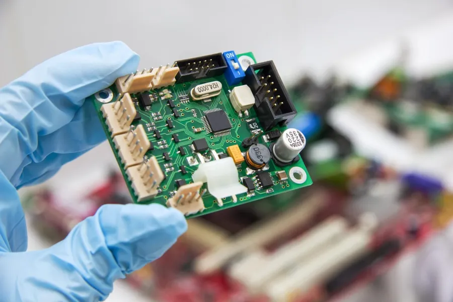
A PC board, or printed circuit board, serves as the foundational platform for electronic devices. It's a non-conductive substrate, typically made of fiberglass, composite epoxy, or other laminated materials, upon which conductive pathways and components are mounted. These pathways, known as traces, etched from copper foil, establish the electrical connections necessary for the device to function. PC boards are integral to virtually all modern electronic systems, from the simplest gadgets to complex industrial machinery.
Differentiating PC Boards from Related Terms: While the terms 'PC board', 'PCB', and 'circuit board' are frequently used interchangeably, they refer to the same component – a board with conductive pathways for electronic components. A 'motherboard', however, is a specific type of PCB, typically found in computers and larger electronic systems. Motherboards provide the primary connection points and core functionality for the entire system, whereas PC boards can refer to any printed circuit board, regardless of its function. The key difference lies in the scale and complexity; a motherboard is typically a larger, more complex PCB.
The basic materials for creating PC boards include the substrate material (such as FR-4, CEM-1, or polyimide), copper foil, solder mask, and silkscreen. These are carefully selected to meet specific performance and environmental requirements. For example, FR-4, a fiberglass-reinforced epoxy laminate, is the most common substrate due to its cost-effectiveness, electrical insulation, and mechanical stability. The copper foil provides the conductive traces, and the solder mask protects the copper traces from oxidation and shorts, whereas the silkscreen layer provides labels and component references, ensuring accurate assembly.
Types of PC Boards: A Comprehensive Overview
PC boards, the foundation of modern electronics, are not monolithic; they come in various types, each tailored to specific application needs. Understanding these variations is crucial for effective design and implementation. This section provides a detailed look at the different types of PC boards, focusing on their unique structures, applications, and advantages.
| Type of PC Board | Structure | Applications | Advantages | Disadvantages |
|---|---|---|---|---|
| Single-Sided | Copper layer on one side of the substrate | Simple electronics, toys, basic control circuits | Low cost, simple design, easy to manufacture | Limited routing, less functionality, not suitable for complex circuits |
| Double-Sided | Copper layers on both sides of the substrate with vias connecting them | Consumer electronics, power supplies, automotive electronics | More flexibility in routing, higher component density, improved performance compared to single-sided boards | More complex and expensive than single-sided boards, but limited layers |
| Multilayer | Multiple layers of copper separated by insulating layers | Advanced electronics, high-performance computing, aerospace applications, servers, telecom equipment | High circuit density, advanced functionality, excellent signal integrity | Higher manufacturing cost, more complex design and fabrication |
| Flexible (Flex) | Flexible substrate material, capable of bending and folding | Wearable electronics, medical devices, automotive dashboard electronics, camera and display connections | Lightweight, flexible, adaptable to different shapes, high signal transmission | Higher cost than rigid boards, more delicate, requires careful handling |
| Rigid-Flex | Combination of rigid and flexible layers | Aerospace, robotics, medical imaging, military electronics | Combines benefits of rigid and flexible boards, customized interconnectivity, reduces overall space and weight | More complex and costly to manufacture than traditional rigid boards |
| Metal Core PCB | Metal core material, typically aluminum or copper, for heat dissipation | High-power electronics, LED lighting, power supplies, automotive electronics | Excellent heat dissipation, increased durability, enhanced thermal management | Heavier and less flexible than other types, more expensive than standard PCBs |
PC Board Manufacturing Process
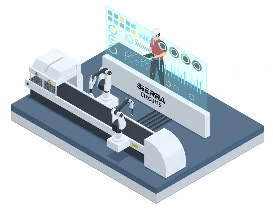
The fabrication of a Printed Circuit Board (PCB), often referred to as a PC board, is a complex multi-stage process that transforms a conceptual design into a functional electronic component. This process encompasses design, material selection, and a series of sophisticated manufacturing steps to ensure accuracy and reliability. The process involves precision engineering and rigorous quality control measures to guarantee that each board meets its intended performance specifications.
The manufacturing process is generally divided into the following key stages:
- PCB Design
This initial stage involves using specialized software to design the schematic and layout of the circuit board. It determines the placement of components, routing of traces, and overall board dimensions. Key considerations include signal integrity, thermal management, and compliance with industry standards. PCB design software is crucial for transforming electrical circuit diagrams into manufacturable board layouts. The output is often in Gerber file format, which is used for fabrication. - Material Selection
The choice of base materials is critical as it affects the board's performance, cost, and environmental impact. Common materials include FR-4 (Flame Retardant 4), which is a fiberglass composite with epoxy resin, as well as more specialized materials like polyimide or ceramic substrates for high-performance applications. Material properties such as dielectric constant, thermal coefficient of expansion, and glass transition temperature are important considerations. - Etching
This process defines the conductive traces on the board. It involves applying a resist (a protective coating) to the copper layer, exposing the board to UV light through a film, developing the exposed areas, and then using chemical etching to remove the unwanted copper. The remaining copper traces will form the circuit paths. Following etching, the resist is removed. - Drilling
Drilling is a precision process that creates holes for mounting components and creating vias (interlayer connections). Computer-controlled drilling machines use extremely precise drill bits to make the necessary holes in the circuit board. The diameter and placement of these holes are critical for the proper assembly and operation of the circuit board. - Plating
Following the drilling, the holes are plated to ensure electrical connection between different layers. The plating process involves depositing a thin layer of metal, typically copper, onto the hole walls. This establishes electrical conductivity and allows for vias to function as vertical conductors through the board. - Solder Mask Application
A solder mask is a protective coating applied to the surface of the PCB, preventing solder from bridging traces during assembly. This green, or sometimes other color, layer also acts as an insulator. This step helps to ensure accurate soldering and reduces the risk of short circuits during component placement. - Silkscreen Printing
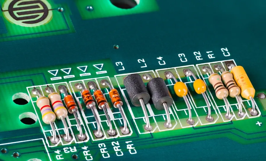
Silkscreen printing adds markings to the board, such as component designators, test points, and manufacturer logos, to assist in assembly and testing. These markings are usually printed in white ink and provide valuable reference points for engineers and technicians working with the board. - Component Assembly
This final stage involves mounting electronic components such as resistors, capacitors, integrated circuits, and connectors onto the board. It can be automated through pick-and-place machines or done manually. The components are either surface-mounted or through-hole mounted, and solder is used to create permanent electrical connections. The components are attached to the PCB with solder, either using reflow oven for surface mount or wave soldering for through-hole components. - Quality Control and Testing
Rigorous quality control measures ensure that the boards meet specified performance requirements. Testing procedures include electrical testing, visual inspections, and functional testing. The process aims to identify any flaws or defects before boards are shipped. Boards that do not pass inspections are sent for rework or scrapped.
Each step of the manufacturing process requires precise control of parameters and conditions, ensuring that the final product is of high quality and performance. Advanced automation techniques, stringent quality control, and skilled professionals contribute to the production of reliable and durable PC boards, which are vital components in modern electronics.
Key Components and Terminology on a PC Board
Understanding the various components and terminology used on a PC board is crucial for both design and troubleshooting. This section provides a detailed explanation of essential elements, enabling a practical grasp of PCB schematics and physical layouts.
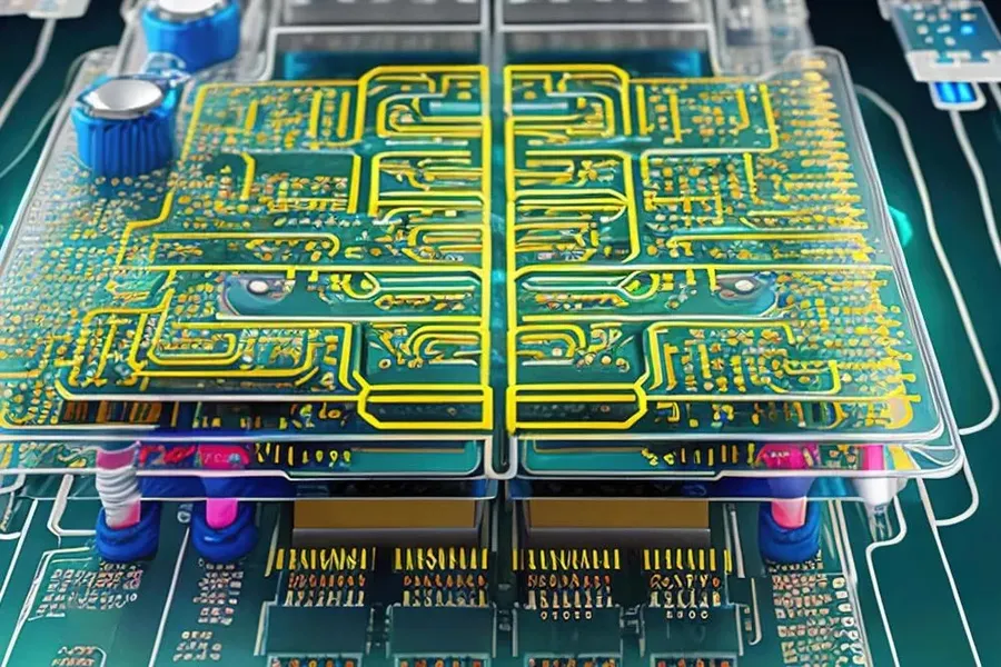
- Traces
Traces are conductive pathways, typically made of copper, that carry electrical signals across the PCB. They are designed with specific widths and spacing to achieve required impedance characteristics and current-carrying capacity. The physical layout of traces directly impacts signal integrity, affecting overall circuit performance and stability. - Vias
Vias are conductive holes that allow electrical connections between different layers of a multi-layer PCB. They are essentially plated-through holes that act as vertical interconnects. Proper via design is crucial to minimize impedance discontinuities and ensure reliable signal transmission across different layers. - Pads
Pads are exposed metal areas on the PCB where component leads are soldered. They provide a secure and reliable mechanical and electrical connection point for components. The size and shape of the pads are critical to ensure proper solder adhesion and component alignment. Additionally, they must be designed to withstand thermal stress during soldering. - Solder Mask
The solder mask is a protective layer, usually a polymer, applied to the PCB except for the areas that need to be soldered. It prevents solder bridging, which can lead to short circuits, and shields traces from corrosion and physical damage. The solder mask improves the reliability of the PCB by ensuring that soldering only occurs where intended, and provides environmental protection. - Silkscreen
The silkscreen is a layer of non-conductive ink, usually white or yellow, used to print component reference designators, test points, company logos, and other information directly on the PCB. It assists in the assembly process and facilitates the identification of components during debugging and maintenance. This layer is essential for clarity and organization during the use of the circuit board.
PC Board Design Considerations
Effective PC board design hinges on a meticulous approach that balances electrical performance, thermal management, and manufacturability. This section outlines crucial design parameters and software tools that are pivotal in creating high-performing and reliable PC boards.
Understanding and adhering to these guidelines ensures not only optimal functionality but also cost-effective production of the final product.
| Design Consideration | Description | Importance |
|---|---|---|
| Layout | Strategic placement of components and routing of traces. | Minimizes signal interference and optimizes circuit performance. |
| Trace Width | The width of conductive paths on the PCB. | Controls current-carrying capacity and impedance. |
| Impedance Control | Ensuring consistent characteristic impedance of signal traces. | Essential for high-speed signal integrity; reduces reflections and signal loss. |
| Thermal Management | Techniques for dissipating heat generated by components. | Prevents overheating and ensures long-term reliability. |
| Signal Integrity | Maintaining the quality of electrical signals as they propagate through the board. | Crucial for reliable operation, especially in high-speed designs. |
Furthermore, the selection of appropriate design software tools is critical to a streamlined design process. These tools enable designers to create intricate layouts, perform simulations, and ensure that the design meets all specified requirements before fabrication.
- PCB Design Software
Software packages like Altium Designer, Eagle, and KiCad provide comprehensive tools for schematic capture, PCB layout, and simulation, thereby accelerating the design cycle and improving accuracy. - Simulation Tools
Simulation tools like SPICE and those integrated into design suites allow engineers to analyze signal behavior and thermal characteristics before physical manufacturing, which is essential for validating the design. - Layout Optimization
The software enables precise control over track geometry, placement of components, and via utilization, thereby reducing signal loss and electromagnetic interference. Good layout optimizes the signal paths and contributes directly to the PC board’s functionality.
PC Board Applications Across Industries
PC boards, also known as printed circuit boards, are the foundational building blocks of modern electronics, enabling the complex functionalities found across diverse industries. Their versatility stems from the ability to create intricate, reliable, and compact electrical interconnections, making them indispensable in everything from everyday consumer devices to highly sophisticated industrial systems.
- Consumer Electronics
PCBs are ubiquitous in consumer electronics, powering devices such as smartphones, laptops, tablets, televisions, and gaming consoles. These boards enable the complex signal processing and control required for modern multimedia and communication devices. The demands in this sector are often for high volume, cost-effective production, and compact designs. - Automotive Industry
The automotive industry relies heavily on PCBs for engine control units (ECUs), infotainment systems, advanced driver-assistance systems (ADAS), and various sensors. These applications often demand high reliability, tolerance to temperature variations and mechanical stress, and strict quality control to ensure safety and performance. Automotive PCBs also often incorporate advanced functionalities for in-vehicle networking and data processing. - Aerospace and Defense
In aerospace and defense, PCBs are crucial for avionics, radar systems, communication equipment, and satellite technology. These applications demand extremely high reliability, precision, and performance under harsh environmental conditions. Weight and size constraints often necessitate the use of high-density interconnect (HDI) PCBs and advanced materials to achieve the required functionality within stringent parameters. - Medical Devices
PCBs play a critical role in medical devices, ranging from diagnostic equipment like MRI and CT scanners to patient monitoring systems and implantable devices. Here, reliability, accuracy, and compliance with stringent medical standards are paramount. Often, these boards must meet specific requirements for biocompatibility, low power consumption, and high precision sensing. - Industrial Automation
In industrial automation, PCBs are integral to programmable logic controllers (PLCs), industrial robots, sensors, and control systems. These boards often need to withstand harsh conditions, such as high temperatures, vibration, and electromagnetic interference. The focus is on ruggedness, reliability, and longevity in demanding environments. Special coatings and design considerations are often used to ensure operational integrity. - Telecommunications
PCBs are essential components in telecommunications infrastructure, including base stations, routers, switches, and network devices. They facilitate high-speed data transmission and communication over various networks. These applications often demand high-frequency performance, impedance control, and careful thermal management to ensure optimal signal integrity and system stability. - Renewable Energy
PCBs are increasingly used in renewable energy systems, such as solar panel inverters, wind turbine control systems, and smart grid technologies. These applications necessitate robust designs that can withstand environmental challenges, including exposure to heat, humidity, and fluctuating power loads. High efficiency power conversion and control circuits are crucial in these systems.
Frequently Asked Questions About PC Boards
This section addresses common inquiries regarding PC boards, clarifying their terminology, function, and relationship to similar components. Understanding these distinctions is crucial for both electronics enthusiasts and industry professionals.
- What does 'PC board' stand for?
The term 'PC board' stands for 'Printed Circuit board'. It's the foundational platform for mounting and electrically connecting electronic components using conductive pathways, pads, and other features etched from copper onto a non-conductive substrate. - Is a PC board the same as a motherboard?
While a motherboard is a type of printed circuit board, it’s specifically the main board in a computer or electronic system, containing the primary connections for crucial components such as the CPU, RAM, and expansion slots. Not all PC boards are motherboards; many are used in various applications that are not computers. - What does 'PC' mean on a circuit board?
The abbreviation 'PC' on a circuit board, as in 'PC board,' refers to 'Printed Circuit'. This indicates that the board’s conductive traces and pads are created using a printing process, differentiating it from older wiring techniques. - What is a PC board used for in AC?
In the context of alternating current (AC) systems, PC boards manage control circuits and power distribution in appliances, HVAC systems, and other AC-powered electronics. They are crucial for directing electrical signals and power, enabling the specific functionalities of these devices. - What is the difference between a PC Board and a PCB?
PC board and PCB (Printed Circuit Board) are essentially interchangeable terms, both refer to the same technology and product. PCB is the more widely recognized and accepted acronym. There is no functional difference between PC boards and PCBs; the terms are used depending on the specific industry and its conventions. - How does a PC board differ from a general circuit board?
The term 'circuit board' is a more general term. All PC boards are circuit boards, but not all circuit boards are PC boards. A circuit board could also refer to breadboards or perfboards that don't use printing to create their conductive pathways. A PC board is a specific type of circuit board made with specific manufacturing processes. - Are PC boards only used in electronic devices?
While PC boards are most commonly associated with electronic devices, their use extends to various other applications. They are utilized in control systems, automotive electronics, medical devices, aerospace, industrial equipment, and more. Anywhere there is a need for an integrated circuit.
Future Trends in PC Board Technology
The PC board industry is experiencing rapid evolution, driven by the relentless pursuit of smaller, faster, and more efficient electronic devices. Future trends in PC board technology are characterized by advancements in materials, miniaturization techniques, high-density interconnect methods, the rise of flexible electronics, and an increasing focus on sustainable manufacturing practices. These innovations are poised to significantly impact the design and functionality of future electronic devices.
- Advanced Materials
The development of new materials with superior electrical, thermal, and mechanical properties is crucial. Research is focused on materials with lower dielectric constants for high-speed signal transmission, better thermal conductivity for efficient heat dissipation, and increased mechanical strength for improved durability. These materials are essential for high performance and reliability in demanding applications. - Miniaturization and High-Density Interconnect (HDI)
Miniaturization is pushing the limits of PC board design, demanding higher interconnect densities and finer features. HDI technology, involving microvias, fine-line traces, and advanced lamination techniques, is becoming increasingly important. These technologies enable the fabrication of smaller, lighter devices with enhanced functionality and performance. - Flexible and Stretchable Electronics
Flexible and stretchable PC boards are breaking free from rigid constraints, enabling new designs and applications. These boards, made with flexible substrates, can conform to complex shapes and withstand mechanical stress, opening up possibilities in wearable devices, medical implants, and automotive electronics. The integration of these flexible circuits is transforming electronic devices to be more adaptable and versatile. - Sustainable and Eco-Friendly Manufacturing
Environmental awareness is driving the development of more sustainable and eco-friendly PCB manufacturing practices. This includes adopting lead-free soldering processes, using recyclable or biodegradable substrates, and implementing efficient energy and waste management strategies. The goal is to minimize the environmental footprint of electronics manufacturing while maintaining product quality and performance. - 3D Printing of PCBs
Additive manufacturing or 3D printing of PCBs is an emerging technology which allows rapid prototyping and customization. This technology enables the creation of complex multilayer designs and integrated electronic components directly from digital files, reducing the lead time and cost for custom designs and small production runs. The technology is also useful for creating unique PCB shapes that are not possible with traditional methods.
The PC board is more than just a component; it is the foundation of modern technology. Understanding the nuances of its construction, design, and applications is essential to appreciating the complexities and advancements of the electronic devices we rely on every day. As technology continues to evolve, the role of the PC board will remain paramount in shaping our future and driving innovation. The PC board, a true unsung hero of the digital age.