Understanding PCB Capacitors: Types, Functions, and Selection
In our increasingly technology-dependent world, electronic devices are at the heart of our daily routines, and PCB capacitors play an indispensable role in their operation. These seemingly small components are fundamental to controlling voltage, storing energy, and ensuring stable current flow within circuits, much like the heart regulates blood flow in the human body. This article will explore the crucial functions, various types, and selection process for PCB capacitors, aiming to illuminate their importance in modern electronics.
What is a PCB Capacitor?
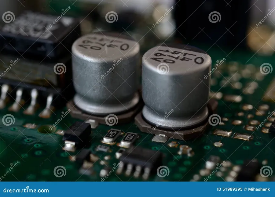
A PCB capacitor is a fundamental electronic component integrated onto a Printed Circuit Board (PCB) that stores electrical energy in an electric field. It consists of two conductive plates, typically metal, separated by a non-conductive material called a dielectric. This basic structure allows the capacitor to accumulate charge when voltage is applied, releasing it when the voltage decreases, thus acting as a temporary reservoir of electrical energy within a circuit.
Capacitors are indispensable in modern electronics, performing various functions from energy storage to signal filtering, which allows for circuit stability and optimized performance.
Key Functions of PCB Capacitors in Circuits
Capacitors are indispensable components in printed circuit boards (PCBs), performing a variety of crucial functions that ensure stable and reliable circuit operation. Their ability to store electrical energy and release it as needed underpins their utility in several applications, including voltage regulation, signal filtering, noise reduction, power surge management, and AC signal coupling.
- Voltage Regulation
Capacitors play a vital role in maintaining a stable voltage level by smoothing out fluctuations in the power supply. They absorb excess voltage when it's high and release it when voltage drops, thereby ensuring a consistent voltage supply to sensitive circuit components. - Filtering (Smoothing)
Capacitors are frequently employed as filters in power circuits, removing high-frequency noise and unwanted AC components from a DC supply. This results in a cleaner, more stable DC voltage. - Decoupling (Noise Reduction)
In digital circuits, capacitors are used for decoupling, meaning they reduce noise on the power rails. By providing a localized charge reservoir near ICs, decoupling capacitors mitigate voltage variations caused by the switching of logic gates, preventing signal degradation. - Energy Storage
Capacitors store electrical energy, providing backup power during short power interruptions or sudden demand spikes. They act like miniature rechargeable batteries to supply a quick burst of energy during high-demand operations or to cover minor power fluctuations. - AC Signal Coupling
Capacitors block DC signals while allowing AC signals to pass through, which is critical in applications where it is necessary to isolate different sections of the circuit. This is essential for AC amplification and signal processing, isolating DC bias from an amplified AC signal.
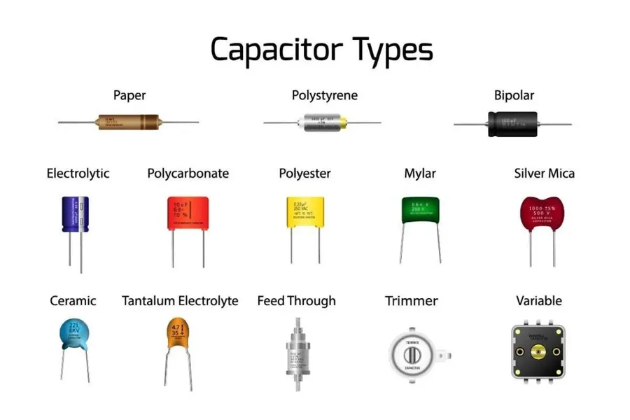
Types of PCB Capacitors
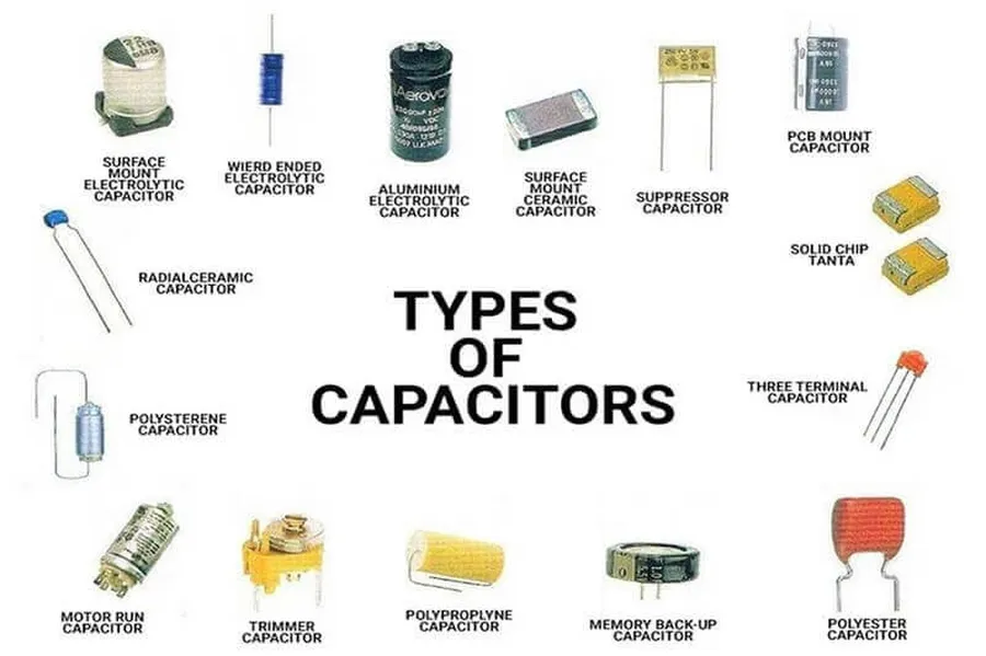
PCB capacitors are essential components in electronic circuits, each type offering unique characteristics suitable for different applications. This section provides a comprehensive overview of the primary types of capacitors used in PCB assemblies, detailing their construction, characteristics, and typical uses.
| Capacitor Type | Dielectric Material | Polarity | Typical Capacitance Range | Key Characteristics | Typical Applications |
|---|---|---|---|---|---|
| Ceramic Capacitors | Ceramic compounds (e.g., barium titanate) | Non-polarized | 1pF to 100µF | Low cost, small size, good high-frequency performance, low ESR | General purpose, bypass, decoupling |
| Electrolytic Capacitors | Aluminum oxide or tantalum oxide | Polarized | 0.1µF to 1F | High capacitance, relatively low cost, Moderate ESR, limited high-frequency performance | Power supply filtering, smoothing, decoupling |
| Tantalum Capacitors | Tantalum pentoxide | Polarized | 0.1µF to 1000µF | High capacitance per volume, good stability, low ESR, Higher cost than Aluminum electrolytic | Critical power, filtering in low voltage, and portable devices |
| Film Capacitors | Plastic films (e.g., polyester, polypropylene) | Non-polarized | 1nF to 100µF | High precision, good stability, low ESR, low temperature coefficient | Audio circuits, precision timing, high-voltage applications |
| Supercapacitors | Porous carbon, metal oxides, or conductive polymers | Polarized | 1F to 1000F+ | Very high capacitance, high energy density, short charge/discharge time | Energy storage, backup power, power smoothing |
- Ceramic Capacitors
These are the most commonly used capacitors in PCB assembly due to their small size, low cost, and good high-frequency performance. They are non-polarized and are made using ceramic dielectric materials. They are widely used in decoupling, bypass, and general-purpose applications. There are different class of ceramic capacitors such as Class 1 (NP0/C0G), Class 2 (X7R/X5R) and Class 3(Y5V), each one having different properties related to temperature variation, and dielectric constant - Electrolytic Capacitors
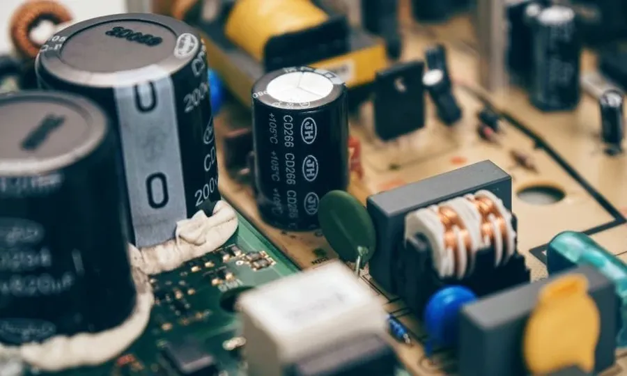
Electrolytic capacitors, typically aluminum or tantalum based, are characterized by their high capacitance values but are polarized devices. They are primarily used for power supply filtering, smoothing, and decoupling where high capacitance is needed. Aluminum electrolytic capacitors are cheaper than Tantalum electrolytic capacitors but Tantalum capacitors typically have better properties such as better ESR and longer life. - Tantalum Capacitors
These capacitors offer good stability, and a high capacitance-to-volume ratio, making them suitable for applications where space is limited and reliability is crucial, but more costly than electrolytic capacitors. They are polarized and are often found in critical power and filtering applications. - Film Capacitors
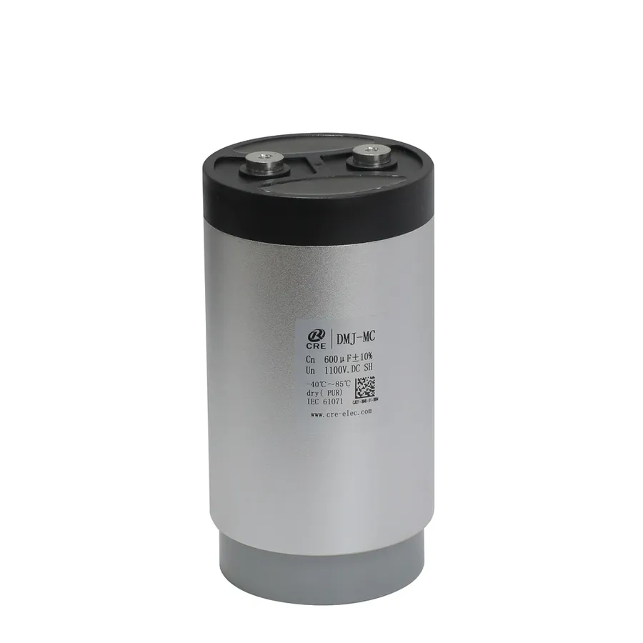
Film capacitors are constructed using plastic films as dielectric materials, providing good stability, low ESR and low temperature coefficient. They are non-polarized and preferred for precision timing circuits, audio circuits, and high-voltage applications where reliability and stability are important. Common film capacitor types include polyester, polypropylene, and polyethylene. - Supercapacitors
Also known as ultracapacitors, these devices store significantly more energy than traditional capacitors, bridging the gap between capacitors and batteries. They feature very high capacitance, with applications in energy storage, power backup, and peak power smoothing, particularly in portable and renewable energy systems. They are polarized.
How to Choose the Right PCB Capacitor
Selecting the appropriate PCB capacitor is crucial for optimal circuit performance and reliability. This process involves carefully considering several key parameters such as capacitor type, capacitance value, voltage rating, tolerance, temperature coefficient, and physical size, all of which must align with the specific circuit requirements and application demands.
| Parameter | Description | Importance |
|---|---|---|
| Capacitor Type | Ceramic, Electrolytic, Tantalum, Film, Supercapacitor | Dictates performance, stability, and cost; choose based on application (e.g., high frequency, high capacitance). |
| Capacitance Value | Measured in Farads (F), often in microfarads (μF) or picofarads (pF). | Determines the amount of charge the capacitor can store, must match the circuit needs for filtering, decoupling, etc. |
| Voltage Rating | Maximum voltage a capacitor can withstand without damage. | Must exceed the maximum voltage expected in the circuit to prevent failure. |
| Tolerance | Percentage variation from the specified capacitance value. | Affects the precision of the circuit, select based on acceptable variation levels. |
| Temperature Coefficient | Describes how capacitance changes with temperature | Important in applications with varying operating temperatures to maintain circuit stability. |
| Physical Size | Dimensions of the capacitor. | Must fit the available space on the PCB and align with surface mount or through-hole requirements. |
Capacitor Markings and Identification
Understanding capacitor markings is crucial for selecting the correct component and ensuring proper circuit functionality. These markings, often found as alphanumeric codes on the capacitor's body, convey critical electrical parameters like capacitance, voltage rating, tolerance, and temperature coefficient. The coding system varies depending on the capacitor type and manufacturer.
Decoding these markings accurately prevents misapplication and ensures that the capacitor operates within its specified limits.
This section elucidates the different coding methods and provides detailed guidance on how to interpret the capacitor markings to accurately identify their electrical parameters.
| Marking Type | Description | Example | Interpretation |
|---|---|---|---|
| Numeric Code (3-digit) | Used primarily for ceramic capacitors. The first two digits are the significant figures, and the third digit indicates the multiplier (power of 10) in picofarads (pF). | 104 | 10 x 10^4 pF = 100,000 pF = 100 nF = 0.1 µF |
| Numeric Code (4-digit) | Similar to 3-digit code, but with three significant digits followed by the multiplier in picofarads (pF). | 1023 | 102 x 10^3 pF = 102,000 pF = 102 nF = 0.102 µF |
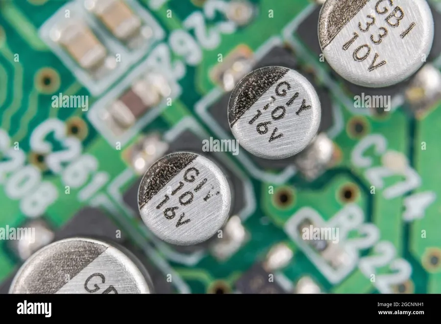
| Alphanumeric Code | Often used for electrolytic and tantalum capacitors. Contains capacitance, voltage, tolerance, and sometimes temperature coefficient information | 47μF 16V | 47 microfarads, 16 volts |
| Letter Codes | Tolerance codes are represented by letters. For example, J is ±5%, K is ±10%, M is ±20%. The letter codes often follow the numerical markings and represent the tolerance of the capacitor value. | 104K | 100 nF, ±10% tolerance |
| Color Codes | Older axial lead capacitors sometimes have color bands. The color bands follow the same rules as resistor color codes, and specify capacitance and tolerance values. | Color Bands | Varies based on color code chart |
Common Capacitor Failures on PCBs
Capacitors, while generally reliable, are susceptible to various failure modes on PCBs, stemming from operational stresses, environmental factors, and the inherent degradation of materials over time. Understanding these failure mechanisms is crucial for effective PCB troubleshooting and maintenance. Identifying the root cause of a capacitor failure not only facilitates repair but also informs better design and material selection practices for future applications.
- Aging and Wear Out
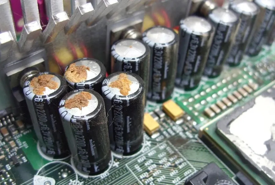
Capacitors, particularly electrolytic types, undergo gradual degradation of their dielectric materials and electrolyte, leading to a decrease in capacitance and an increase in equivalent series resistance (ESR) over time. This is an inevitable process that is accelerated by high operating temperatures and ripple currents. - Over-Voltage Stress
Exceeding the rated voltage of a capacitor can cause dielectric breakdown. This manifests as a short circuit or a drastic reduction in capacitance, often with visible signs of damage such as bulging or cracking of the capacitor's casing. - Over-Temperature Exposure
Elevated temperatures, whether due to ambient conditions or excessive current flow, can severely impact the performance and lifespan of a capacitor. The electrolyte in electrolytic capacitors can dry out, leading to increased ESR and eventual failure. Other types of capacitors might experience changes in their dielectric properties or physical damage such as cracking. - Reverse Voltage Application
Applying a reverse polarity voltage to polarized capacitors, such as electrolytic and tantalum types, can cause immediate and catastrophic damage. This is often seen as the capacitor exploding or emitting smoke, and is a direct result of the dielectric being unable to withstand reverse polarization. - Physical Damage
Mechanical stresses, such as bending of the PCB, shocks, or impacts, can cause physical damage to capacitors, resulting in internal shorts, cracks in the ceramic or dielectric, and loss of electrical connection. Such damage can result in sudden failure or a gradual degradation of the capacitor's performance. - Excessive Ripple Current
Excessive ripple current, which is AC current superimposed on DC, generates heat within the capacitor due to ESR. This can accelerate degradation, cause the electrolyte to dry out, and result in overheating and a decrease in performance, especially in electrolytic capacitors.
Symptoms of a failing capacitor can include unexpected circuit behavior, such as intermittent operation, increased noise, or complete system failure. Visual inspection may reveal bulging or leakage, especially in electrolytic capacitors. However, not all failures are visually apparent; therefore, testing with a multimeter becomes essential.
Testing a capacitor involves measuring its capacitance, ESR, and leakage current. A multimeter can be used to check for shorts or open circuits by measuring resistance, which should be very high (ideally, an open circuit) for a healthy capacitor. A dedicated capacitance meter is required for accurate capacitance measurements. For more precise diagnosis, an ESR meter can be employed, since increased ESR often precedes other failure symptoms. It is important to follow the recommended safety procedures when testing capacitors, which may include discharging them to avoid electrical shock.
Proper Handling and Disposal of PCB Capacitors
Proper handling and disposal of PCB capacitors are crucial to prevent damage, ensure longevity, and mitigate environmental risks. Capacitors, while seemingly robust, can be sensitive to mishandling and improper disposal, potentially leading to premature failure or environmental contamination.
- Handling Precautions
Always handle capacitors with care, avoiding physical shocks, impacts, and excessive bending of leads. Use appropriate tools for handling and soldering to prevent damage. Avoid touching the capacitor's conductive surfaces with bare hands to prevent contamination and potential static discharge. - Storage Best Practices
Store capacitors in a dry, controlled environment with stable temperature and humidity. Avoid exposure to direct sunlight, extreme temperatures, and corrosive substances. Keep components in their original packaging or in anti-static containers to prevent damage from electrostatic discharge (ESD). - Disposal of Different Capacitor Types
Different capacitor types require different disposal methods. Ceramic capacitors are generally considered non-hazardous and can be disposed of as electronic waste. Electrolytic and tantalum capacitors, however, may contain materials that require specialized treatment to ensure environmental safety. Film capacitors may contain materials like polypropylene or polyester, which should be disposed of according to local regulations. - Safe Disposal Procedures for Older PCBs
Older PCBs often contain capacitors with potentially hazardous substances. These should be handled with extra care. Always follow local environmental regulations for the disposal of electronic waste. Many jurisdictions have established collection and recycling programs for electronic waste and old PCBs. Do not dispose of old PCBs containing capacitors as regular trash; instead, opt for certified electronic waste recycling facilities. - Recycling and Resource Recovery
Whenever possible, explore recycling options for capacitors and PCBs. Recycling can help recover valuable materials and reduce the environmental impact of electronic waste. Look for certified recyclers who can safely process and recover materials from capacitors and PCBs.
Frequently Asked Questions About PCB Capacitors
This section addresses common questions regarding PCB capacitors, providing clear and concise answers to enhance understanding and practical application of these essential electronic components. By focusing on fundamental queries, we aim to clarify their role, selection criteria, and potential issues.
- What is the fundamental function of a capacitor in a PCB?
A capacitor in a PCB primarily functions as a temporary energy storage device. It stores electrical energy in an electric field created between two conductive plates separated by a dielectric material. This stored energy can be released when needed, enabling various circuit functions like filtering, decoupling, and timing. - What distinguishes a 104 capacitor from a 103 capacitor?
Capacitor codes like '104' and '103' represent their capacitance value. The first two digits indicate the significant figures, and the last digit indicates the number of zeros. Thus, '104' represents 10 followed by four zeros in picofarads (pF), or 100,000 pF (100 nF), while '103' represents 10 followed by three zeros in picofarads, or 10,000 pF (10 nF). The difference is a factor of 10 in their capacitance values. - Why are capacitors essential components in circuit designs?
Capacitors serve multiple critical roles. They are used for filtering out unwanted noise in power supplies, ensuring a stable voltage; for decoupling, preventing noise from propagating between different parts of the circuit; for storing charge for short durations, and for timing circuits due to their ability to charge and discharge predictably. - What are the typical consequences of a capacitor failure on a circuit board?
A failed capacitor can manifest in various ways, including a short circuit causing the circuit board to malfunction, an open circuit causing a loss of function, or a change in capacitance leading to unstable circuit behavior. Common symptoms include unexpected voltage drops, device reset, noise, overheating or circuit failure. - How does a capacitor filter noise on a PCB?
Capacitors filter noise by acting as a low impedance path for high frequency signals, such as noise, while blocking DC or lower frequencies. This is due to their reactance decreasing with frequency. When placed parallel to the signal path, noise is shunted away from the signal to ground and thus filtering the signal to a cleaner output - What does the voltage rating of a capacitor signify?
The voltage rating specifies the maximum voltage a capacitor can safely withstand without damage or failure. It is critical to select a capacitor with a voltage rating that meets or exceeds the maximum voltage expected in the application. Exceeding the voltage rating can cause the dielectric to break down, potentially resulting in a short circuit and component damage. - How do temperature variations affect the performance of PCB capacitors?
Temperature can significantly impact the characteristics of capacitors, particularly electrolytic types where extreme temperature variations can decrease the lifespan or cause premature failure. Some capacitors have stable capacitance over a wide range of temperatures while others do not so proper capacitor selection is important for the intended temperature range.
Advanced Applications and Trends in PCB Capacitors
The field of PCB capacitors is rapidly evolving, driven by the increasing demands of modern electronics. Current trends focus on improving performance, miniaturization, and integration to meet the needs of emerging technologies. These advancements are crucial for applications in electric vehicles, artificial intelligence (AI), renewable energy systems, and beyond.
Key trends include the development of advanced materials, high-density capacitors, and new mounting techniques.
- Advanced Materials
Researchers are exploring novel dielectric materials to achieve higher capacitance values in smaller packages. This includes materials with higher permittivity and lower loss tangents. Examples include using new ceramics and polymer composites to enhance performance, reliability, and temperature stability, enabling capacitors to operate under more extreme conditions. - High-Density Capacitors
Driven by the trend of miniaturization, there's a significant push towards developing high-density capacitors. Multilayer ceramic capacitors (MLCCs) are continuously being refined to maximize capacitance within a given volume. Innovative designs, like 3D stacking and thin-film technologies, are enabling greater capacitance per unit area. This is crucial for densely populated PCBs where space is at a premium. - Integration and Mounting Innovations
Emerging trends involve integrating capacitors directly within semiconductor packages or substrates for reduced size and improved performance. This includes techniques like capacitor-on-substrate (CoS) and embedded capacitor technologies. Additionally, new mounting methods such as flip-chip and surface-mount variations are designed to improve both electrical and thermal performance while reducing manufacturing complexity. These methods also facilitate better heat dissipation, extending the capacitor's lifespan. - Applications in Emerging Technologies
Capacitors play a crucial role in emerging sectors. In electric vehicles, they are used for energy storage and power smoothing in inverter circuits. In AI applications, they are critical for power management in high-performance computing chips and memory modules. For renewable energy systems, capacitors are essential for filtering and stabilization within solar and wind power inverters.
From filtering noise to storing energy, the functionality of a PCB capacitor is integral to the seamless operation of electronics in every sector of modern society. Understanding their types, functions, and how to select the right one is essential for any project requiring electronic circuitry. As technology evolves, so do the demands on capacitors and it is critical to stay up to date on advanced materials, high density capacitors and their role in the future. By keeping an eye on the future and properly maintaining and disposing of PCB capacitors, engineers and hobbyists alike can ensure the reliability and longevity of their projects.