Understanding Rigid PCBs: Design, Materials, and Applications
In today's world, nearly every electronic device we use relies on the unseen foundation of a printed circuit board, or PCB. Among the many types, the rigid PCB stands as a foundational building block, providing a stable, non-flexible platform for electronic components. This article delves into the details of rigid PCBs, exploring their core properties, the materials they're made of, their manufacturing process, and the diverse applications they support. By understanding their characteristics and limitations, we can make informed decisions about their use in our technological creations.
What is a Rigid PCB?
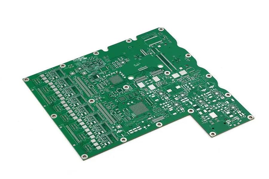
A rigid printed circuit board (PCB) is a foundational component in electronics, characterized by its solid and inflexible structure. Unlike flexible PCBs, rigid PCBs maintain a fixed shape due to their construction from a rigid substrate material. This inherent rigidity provides mechanical stability and support for mounted electronic components, making them ideal for a vast array of applications.
Rigid PCBs are typically constructed using layers of non-conductive materials like FR-4 (a fiberglass composite), CEM-1 (a paper-based composite), or metal cores, with copper traces etched onto the substrate to form conductive pathways. This layered structure provides both electrical insulation and conductive routing. The lack of flexibility means they cannot be easily bent or folded without damage, a key distinguishing factor compared to flexible PCBs. Rigid-flex PCBs combine rigid and flexible sections into a single board, offering a hybrid approach, whereas rigid PCBs remain solely inflexible.
Materials Used in Rigid PCB Fabrication
The selection of materials for rigid Printed Circuit Boards (PCBs) is paramount, directly influencing their thermal, electrical, and mechanical performance. These materials, primarily substrates, provide the structural base for the conductive pathways and electronic components.
| Material | Description | Advantages | Limitations | Common Applications |
|---|---|---|---|---|
| FR-4 | A composite material made of woven fiberglass cloth with epoxy resin. | Widely available, cost-effective, good mechanical strength, good electrical properties. | Moderate thermal performance, not suitable for high-frequency applications, relatively high dielectric loss at high frequencies. | Consumer electronics, general purpose boards, low cost applications |
| CEM-1 | A composite material made of paper core with a layer of woven fiberglass and epoxy resin. | Lower cost compared to FR-4, easier to machine, good electrical properties. | Lower mechanical strength compared to FR-4, higher moisture absorption. | Single-sided PCBs, low cost applications, consumer electronics |
| Metal Core (Aluminum/Copper) | A metal base (typically aluminum or copper) with a dielectric layer on top. | Excellent thermal conductivity, high mechanical strength, good heat dissipation. | Higher cost, heavier than FR-4, complex fabrication process. | High-power electronics, LED lighting, automotive electronics, power supplies |
| Polyimide | A high-performance polymer. | Excellent thermal stability, high temperature resistance, good flexibility, good electrical properties. | Expensive, more difficult to process, higher moisture absorption compared to FR-4. | High-temperature electronics, aerospace applications, flexible electronics |
| PTFE (Teflon) | A fluoropolymer material | Excellent electrical properties, low dielectric loss, very high frequency applications, good thermal stability. | High cost, difficult to process, limited adhesion properties. | High-frequency applications, radar systems, microwave devices, aerospace |
Types of Rigid PCBs
Rigid PCBs are categorized based on the number of conductive layers they incorporate, each type catering to specific application needs with varying complexity and cost implications. The most common types are single-layer, double-layer, and multi-layer PCBs.
| Type of Rigid PCB | Description | Typical Applications | Complexity | Cost Considerations |
|---|---|---|---|---|
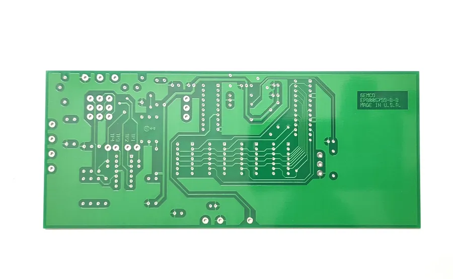
| Single-Layer PCB | Contains one layer of conductive material, with components mounted on one side. | Simple electronic devices, LED lighting, basic sensors, and low-density circuits. | Least complex design and manufacturing process. | Lowest cost due to simplicity and fewer fabrication steps. |
| Double-Layer PCB | Features two conductive layers, one on each side of the substrate, interconnected via vias. | Power supplies, audio equipment, simple control systems, and moderate-complexity circuits. | Medium complexity, requiring vias for interconnection, which increases manufacturing effort. | Moderate cost, more expensive than single-layer PCBs but still economical. |
| Multi-Layer PCB | Consists of three or more layers of conductive material, separated by insulating layers, allowing for complex interconnections. | Complex electronics, high-speed computing, advanced telecommunications, high-density circuits. | Most complex design and manufacturing process involving precision alignment and lamination. | Highest cost due to increased materials, precision requirements, and manufacturing steps. |
Rigid PCB Manufacturing Process
The fabrication of rigid PCBs involves a precise sequence of processes, transforming raw materials into functional circuit boards. This section outlines these key manufacturing steps, emphasizing the techniques used to ensure the creation of reliable and high-quality PCBs.
- Design and Layout
The process begins with the electronic design, typically using CAD software. This step involves defining the circuit schematic, component placement, and routing of traces. The design is then translated into a Gerber file format, which is the industry standard for PCB fabrication. - Material Selection
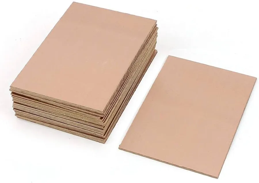
Choosing the appropriate substrate material is crucial. FR-4 is the most common choice due to its balance of cost, electrical properties, and mechanical strength. Other materials like CEM-1 or metal cores may be selected based on specific performance requirements. Copper foil is selected for conducting traces. - Pattern Transfer
The circuit pattern is transferred onto the copper-clad substrate using a photolithographic process. A photoresist layer is applied, exposed to UV light through a film mask, and then developed, leaving the desired circuit pattern on the copper. - Etching
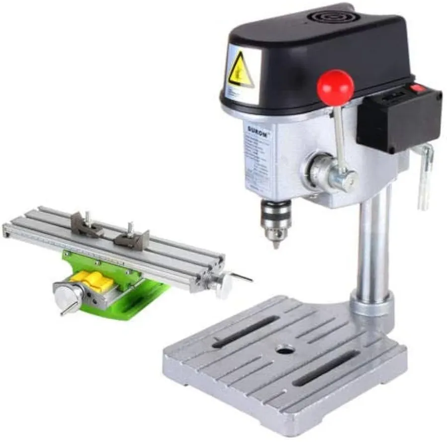
Etching is a chemical process that removes the unwanted copper, leaving only the conductive traces and pads. The substrate is immersed in an etching solution, carefully controlled to achieve the accurate circuit pattern. - Drilling
Holes for component mounting and vias are drilled using precise computer-controlled drills. Different drill bit sizes are used depending on the component requirements and design specifications. - Plating
After drilling, the holes are plated with copper to create conductive vias, and also for surface finish. Electroless and electrolytic plating techniques are used to deposit a uniform layer of copper. - Solder Mask Application
A solder mask, a protective polymer layer, is applied to the board, leaving only the pads exposed for soldering components. It is typically applied using screen printing or photosensitive methods. This mask prevents solder bridging and ensures reliable soldering during assembly. - Surface Finish
The exposed copper pads are finished with a surface treatment like HASL, ENIG, or immersion silver for better solderability and to prevent oxidation. The surface finish is essential for reliable component assembly and long-term performance. - Silkscreen Printing
Silkscreen printing is often applied to the solder mask to add component designators, logos, and other relevant information for easier identification and assembly. - Electrical Testing
Each fabricated PCB is electrically tested to ensure that the circuits are functional and meet the design requirements. This includes continuity testing and resistance measurements to identify any faults or shorts. - Profiling
The final step involves cutting the PCB out of the main panel using routing or laser cutting, creating the desired board shape. - Quality Control
The finished PCBs are then subjected to rigorous quality control checks, ensuring they conform to dimensional, electrical, and visual standards before packaging and delivery.
Advantages of Using Rigid PCBs
Rigid PCBs offer several compelling advantages, primarily stemming from their inherent solid structure. These benefits make them a cornerstone in a vast array of electronic applications, providing stability, reliability, and cost-effectiveness where flexibility is not a primary requirement.
- High Mechanical Stability
The rigid nature of these PCBs provides excellent structural support for mounted components, preventing bending or flexing under normal operational conditions. This stability is critical in applications where component placement and alignment are crucial for consistent performance. - Superior Reliability
Due to their robust design, rigid PCBs offer high reliability and durability. They are less prone to damage from handling or environmental stress compared to flexible alternatives, making them suitable for applications with demanding operational requirements. - Cost-Effectiveness
Rigid PCBs are generally more cost-effective to manufacture than flexible or rigid-flex PCBs, especially for high-volume production runs. The simpler manufacturing processes and lower material costs contribute to their overall affordability. - Established Manufacturing Processes
The manufacturing processes for rigid PCBs are well-established and widely available, resulting in consistent quality and easier access to production facilities. This mature infrastructure ensures dependable fabrication and shorter lead times. - Excellent Heat Dissipation
Rigid PCBs, especially those utilizing materials such as metal cores, can provide better heat dissipation than flexible PCBs. This is crucial for high-power applications where thermal management is a key consideration to prevent component failure and system malfunction. - Component Density
Rigid PCBs facilitate high component density, allowing for more complex circuits to be integrated into a smaller footprint. This is particularly beneficial for applications that require miniaturization without sacrificing functionality.
Limitations of Rigid PCBs
Despite their widespread use, rigid PCBs possess inherent limitations that must be considered in electronic design. These limitations primarily stem from their inflexible nature, which can hinder their application in certain scenarios requiring adaptability or compact form factors. Understanding these shortcomings is crucial for making informed decisions about PCB selection.
- Lack of Flexibility
The primary limitation of rigid PCBs is their inflexibility. They cannot bend or conform to non-planar surfaces, which restricts their use in applications requiring curved or flexible designs. This inflexibility also makes them prone to damage under mechanical stress or bending. - Space Constraints
Rigid PCBs can be challenging to integrate into compact or irregularly shaped devices. Their fixed dimensions require more space and may lead to design compromises. This is a significant drawback for small, portable, and wearable electronics. - Limited Dynamic Movement
Rigid PCBs cannot accommodate dynamic movement or flexing, rendering them unsuitable for applications that require moving parts or vibration resistance, or in environments with high physical stress. Repeated flexing of rigid PCBs results in mechanical stress and lead to the possibility of fractures of traces and component joints. - Assembly Challenges in Complex Systems
Integrating multiple rigid PCBs into complex systems can create assembly challenges. The need for connectors, wire harnesses, and mounting hardware to connect multiple boards can add to cost, increase system size, and decrease overall reliability. The use of rigid PCBs also require more complex cable management. - Thermal Stress Limitations
Rigid PCBs can be susceptible to thermal stress in environments with varying temperatures. Rapid changes in temperature can cause expansion and contraction in the PCB materials, potentially leading to stress-related damage, especially at solder joints and vias. The Coefficient of Thermal Expansion (CTE) mismatch between different materials in a rigid PCB can lead to reliability issues over time.
Rigid PCB Applications
Rigid PCBs are foundational components across a vast spectrum of electronic devices, primarily due to their structural integrity and reliable performance. Their stable form factor enables the precise and robust mounting of components, making them ideal for applications requiring consistent operational parameters.
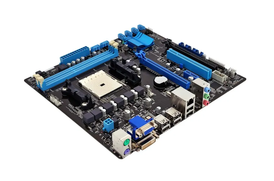
- Computer Motherboards
The cornerstone of desktop and laptop computers, motherboards utilize multi-layer rigid PCBs to connect and manage complex processing, memory, and peripheral components. The rigid nature of these PCBs ensures that high-speed data transmission occurs with minimal signal degradation. - Industrial Controls
Rigid PCBs are employed extensively in industrial automation systems, including programmable logic controllers (PLCs), robotic control systems, and machinery interfaces. Their ruggedness is crucial for withstanding harsh operating conditions, and the stability provided is critical for precise and repeatable operations. - Automotive Electronics
In automotive applications, rigid PCBs are essential for control units, engine management systems, infotainment systems, and advanced driver-assistance systems (ADAS). Their durability and reliability are paramount given the demanding environments of heat, vibration, and electrical noise within vehicles. High-temperature materials such as FR-4 with high Tg values, or ceramic-based substrates may be employed for extreme environments. - Medical Equipment
Rigid PCBs are found in a wide range of medical devices, including diagnostic equipment, patient monitoring systems, and therapeutic devices. Precision and reliability are essential in this field, and the predictable performance of rigid PCBs contributes directly to the accuracy of diagnostic and treatment procedures. The non-reactive nature of materials like FR-4 makes them well-suited for this field. - Consumer Gadgets
From smartphones and tablets to televisions, gaming consoles, and home appliances, rigid PCBs are the underlying platform for consumer electronics. Their cost-effectiveness, combined with the ability to accommodate complex circuit designs, makes them suitable for mass production. Additionally, the mechanical strength provided contributes to the structural robustness of the finished devices. - Telecommunications Infrastructure
Rigid PCBs are critical in network routers, switches, and base stations. The stability and signal integrity afforded by rigid PCBs are crucial for maintaining reliable high-speed data transfer in telecom networks. Layer counts vary depending on the complexity of the application from low layer count signal routing to very complex multi-layer designs for high speed signal processing - Aerospace Systems
Within aerospace, rigid PCBs are used in flight control systems, navigation systems, and communication equipment. The reliability and thermal management capabilities are paramount in the extreme conditions encountered in aerospace applications. Materials such as Polyimide and special high-Tg FR-4 are often employed for their robustness.
Rigid vs. Flexible PCBs: Key Differences
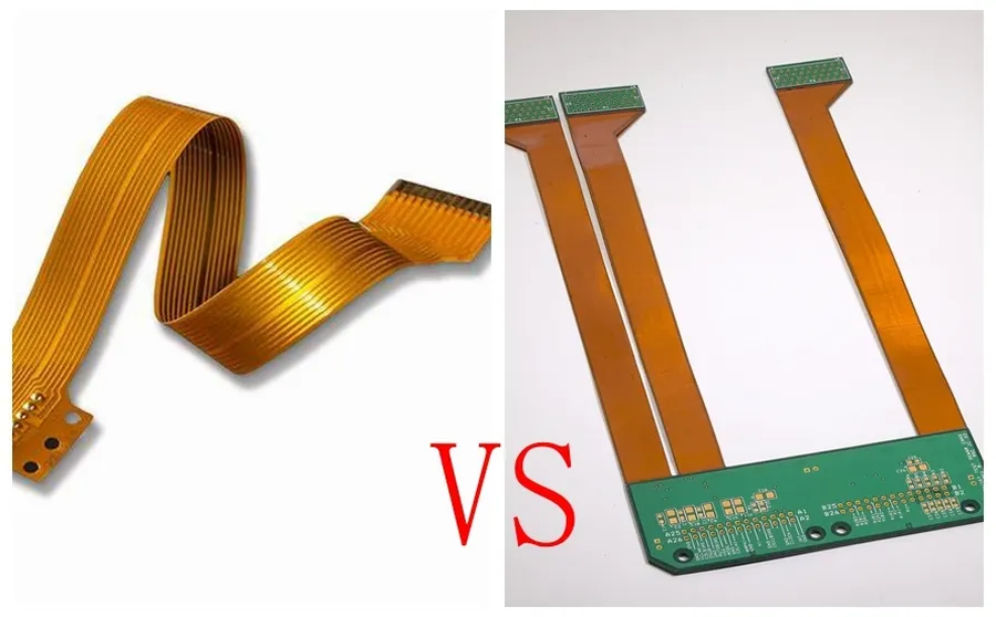
Rigid and flexible PCBs represent two distinct approaches to circuit board design, each catering to different application needs. Understanding their fundamental differences is crucial for selecting the appropriate technology for a given electronic product. Rigid PCBs, characterized by their solid, unbending structure, contrast sharply with flexible PCBs, which are designed to bend and conform to various shapes.
| Feature | Rigid PCB | Flexible PCB |
|---|---|---|
| Flexibility | Inflexible, maintains a solid shape | Highly flexible, can bend and fold |
| Material | Typically FR-4, CEM-1, or metal core | Polyimide, polyester, or other flexible substrates |
| Cost | Generally less expensive for basic designs | Generally more expensive due to specialized materials and processing |
| Durability | Very durable and resistant to mechanical stress within its defined form | Excellent in dynamic applications where flexing is required, but can be more susceptible to damage with extreme or repeated bending |
| Space Utilization | Requires defined physical space, less efficient for complex, compact designs | Can conform to tight spaces, allowing for more compact and complex designs |
| Application | Ideal for static applications (e.g., motherboards, power supplies) | Ideal for dynamic applications (e.g., wearables, cameras, interconnects with moving parts) |
| Manufacturing | Well-established and standardized manufacturing process | Requires specialized manufacturing processes and equipment |
| Assembly | Standard assembly processes | May require special assembly processes due to flexibility |
Frequently Asked Questions About Rigid PCBs
This section addresses common inquiries about rigid PCBs, providing clear and concise answers to help you understand their characteristics, applications, and differences compared to other PCB types. We will tackle questions related to their advantages, limitations, and when to consider alternative options such as flexible or rigid-flex PCBs.
- What exactly is a rigid PCB?
A rigid PCB, or printed circuit board, is a solid, inflexible board made from a rigid substrate material. This substrate, often FR-4, provides a stable base for mounting and connecting electronic components. Unlike flexible PCBs, rigid PCBs cannot bend or flex after manufacturing. - What differentiates a rigid PCB from a flexible PCB?
The primary difference lies in their flexibility. Rigid PCBs are solid and inflexible, while flexible PCBs are designed to bend and conform to different shapes. This difference in flexibility dictates their applications. Rigid PCBs are generally used in static applications, while flexible PCBs are used where bending or repeated flexing is required. - What are the typical disadvantages of using rigid PCBs?
Rigid PCBs, while robust, are limited by their inflexibility. This lack of flexibility can make them unsuitable for applications with space constraints or those requiring complex shapes. They also are not ideal for high-vibration environments and can be more difficult to assemble in tight or complex enclosures compared to flexible alternatives. - When should I consider using a rigid-flex PCB instead of a standard rigid PCB?
Rigid-flex PCBs combine rigid and flexible PCB sections into a single board, allowing for both stability and flexibility. You should consider using a rigid-flex PCB when your design requires elements of both, such as when you need to mount components on a rigid section, but still need connections that can flex and bend. These boards are often used in scenarios where space is limited and a single board solution reduces assembly complexity. - Are rigid PCBs more cost-effective than flexible PCBs?
Generally, rigid PCBs are more cost-effective than flexible PCBs for simple designs and high-volume production. The fabrication process for rigid PCBs is more established and less complex, making them a more affordable option for many applications. Flexible PCBs typically have higher fabrication costs due to their material and manufacturing process. - What are some common applications for rigid PCBs?
Rigid PCBs are extensively used across many industries. Common applications include computer motherboards, power supplies, control systems, consumer electronics, automotive electronics, and many other electronic devices where a stable and reliable platform is required for component mounting and interconnection. Their wide range of applications is a result of their cost-effectiveness and reliability. - How does the number of layers affect the performance and cost of a rigid PCB?
The number of layers on a rigid PCB directly impacts its complexity, cost, and performance. Single and double layer PCBs are more affordable but are limited in routing and functionality. Multi-layer PCBs are more complex, allowing for denser routing and more functionality, making them suitable for high-performance devices but come with a higher production cost.
Cost Factors in Rigid PCB Production
The cost of producing rigid PCBs is influenced by a multitude of factors, spanning material choices, design complexity, and manufacturing processes. Understanding these elements is critical for cost optimization without sacrificing the required performance and quality of the final product.
| Cost Factor | Description | Impact on Cost |
|---|---|---|
| Material Choices | The type of substrate material (e.g., FR-4, CEM-1, metal core) directly impacts cost. FR-4 is common and cost-effective, while specialized materials like metal cores are more expensive. | Higher cost for advanced materials; Lower for standard ones. |
| Layer Count | Single-layer PCBs are the least expensive, followed by double-layer PCBs. Multi-layer PCBs significantly increase cost due to the complexity and resources involved in their fabrication. | Linear increase with layer count; exponential beyond four layers. |
| Board Size | Larger boards require more material, resulting in increased costs. | Directly proportional to size. |
| Manufacturing Complexity | Factors like the number of vias, drilling requirements, trace width, and the need for specific finishes add to the complexity and subsequently increase cost. | Higher for fine-pitch designs, BGA's, and blind/buried vias; lower for less complex designs. |
| Surface Finish | Different surface finishes such as HASL, ENIG, or Immersion Silver affect the cost. ENIG and other advanced finishes are more expensive than HASL. | Premium finishes add to the overall cost. |
| Quantity | Larger production runs often benefit from economies of scale, resulting in a lower per-unit cost. | Lower per-unit cost at higher quantities |
| Tolerances | Tighter tolerances require more precise manufacturing processes, leading to an increased cost. | Higher for tighter tolerances; lower for standard tolerance requirements |
| Lead Time | Shorter lead times typically incur extra costs due to expedited manufacturing and processing. | Rush production will add to the cost |
To optimize costs, careful consideration should be given to material selection, minimizing layer counts, optimizing board size to meet the application, and standardizing design rules. Additionally, collaborating closely with PCB manufacturers, choosing the right surface finish for the application, and planning production volumes effectively are critical strategies for reducing overall production expenses without compromising quality and performance.
Rigid PCBs are the workhorses of the electronics industry, offering a dependable and cost-effective solution for a wide variety of applications. While they lack the flexibility of other PCB types, their stability and reliability make them indispensable for numerous electronic devices. Understanding the nuances of rigid PCB design, materials, and manufacturing processes is crucial for anyone involved in electronics. As we continue to push technological boundaries, these fundamental components will remain at the heart of innovation, providing a solid foundation for advancements in various industries.