Unlocking Circuit Design: PCB Breadboards for Every Project
In the realm of electronics, the transition from abstract ideas to tangible circuits is crucial. PCB breadboards, the unsung heroes of prototyping, allow enthusiasts and professionals alike to experiment and iterate without the commitment of soldering. This article will be your guide, exploring the versatility and benefits of using PCB breadboards to bring your electronics projects to life, bridging the world of design with real applications. We’ll unravel their various forms and show you how they’re instrumental in electronics.
Understanding the Basics: What is a PCB Breadboard?
A PCB breadboard, at its core, represents a fusion of the user-friendly nature of a solderless breadboard with the inherent robustness of a printed circuit board (PCB). This innovative approach provides a more stable and durable platform for prototyping and testing electronic circuits compared to traditional plastic breadboards. By integrating the copper traces and through-holes found on a PCB, it facilitates a more permanent setup, reducing the common issues associated with loose connections and accidental disconnections encountered in conventional breadboards.
Types of PCB Breadboards: A Closer Look
PCB breadboards serve as a bridge between the flexibility of solderless breadboards and the reliability of permanent PCBs, offering various designs to suit diverse prototyping needs. Understanding these types is crucial for effective project planning and execution.
- Solderable PCB Breadboards
These boards provide a robust platform for more permanent prototypes. They feature pads or through-holes where components can be soldered, creating durable connections. Ideal for projects that require stability and longevity beyond initial testing. - Perfboard-Style PCB Breadboards
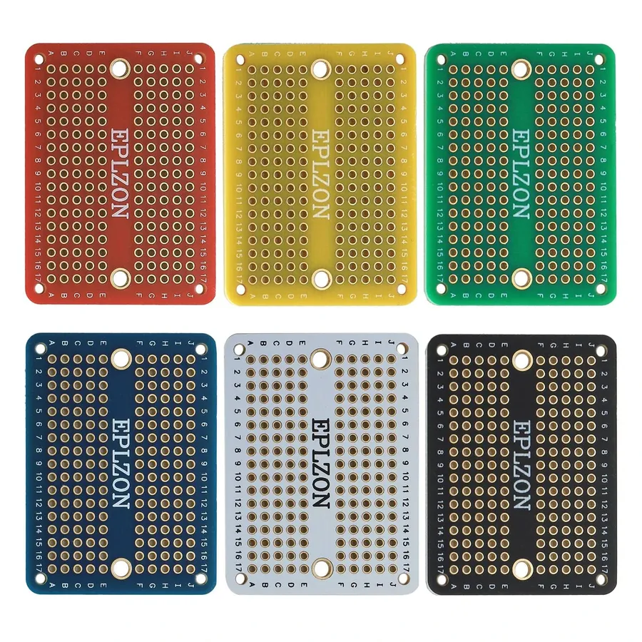
Characterized by a grid of holes without pre-defined circuit paths, perfboards offer a high degree of flexibility for custom circuit arrangements. Components can be interconnected using wire-wrapping, solder, or conductive epoxy, allowing for complex and unconventional layouts. - Standard Layout PCB Breadboards
These are designed to mimic the layout of traditional solderless breadboards, with interconnected strips that enable quick component placement and signal tracing. The primary difference is they offer a more durable and semi-permanent testing platform, reducing the loose connections found in traditional breadboards.
| Type of PCB Breadboard | Key Features | Best Use Cases | Connection Method |
|---|---|---|---|
| Solderable | Durable, solderable pads or through-holes | Robust and Semi-permanent Prototypes, Projects that need increased stability | Soldering |
| Perfboard-Style | Grid of holes for custom circuit layouts | Customized, complex circuits, flexible layouts | Wire-Wrapping, Solder, or Conductive Epoxy |
| Standard Layout | Matches solderless breadboard layouts | Quick setup and testing, direct replacement for traditional breadboards | Soldering |
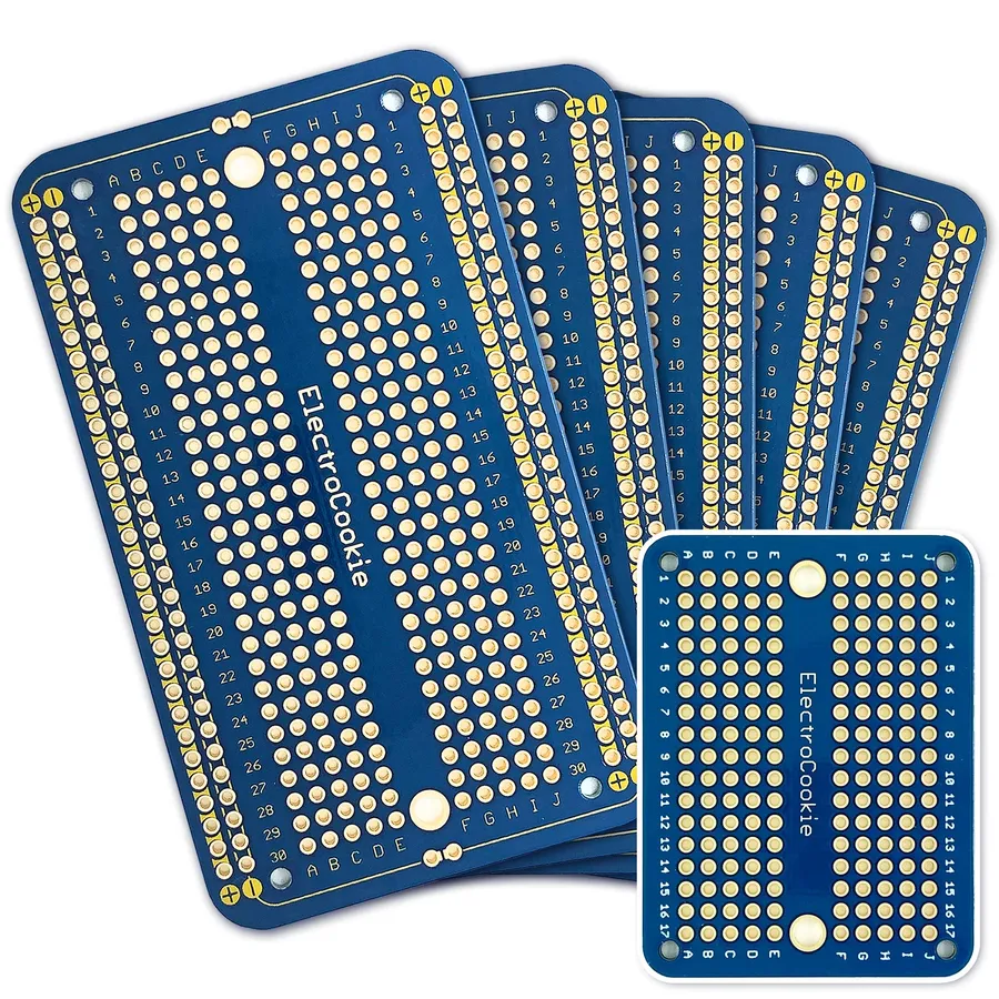
Solderable PCB Breadboards: The Durable Option
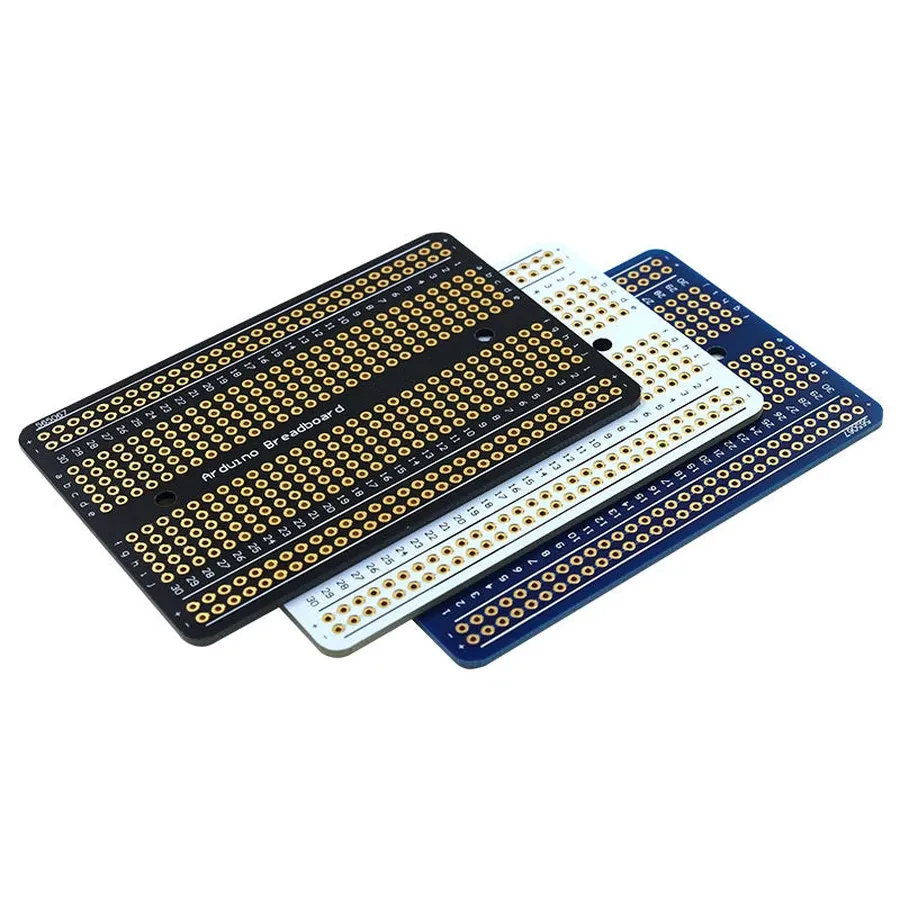
Solderable PCB breadboards represent a significant step up in robustness and permanence from standard solderless breadboards. Designed with a copper grid on a PCB substrate, these boards allow components to be soldered directly onto the surface, creating a more secure and reliable electrical connection ideal for prototypes that require extended testing or need to withstand physical stress. This design bridges the gap between temporary breadboarding and a final custom PCB design.
Unlike their solderless counterparts, solderable breadboards are intended for more permanent circuit construction. Here’s a breakdown of the pros and cons:
| Feature | Solderable PCB Breadboard | Standard Solderless Breadboard |
|---|---|---|
| Durability | High; soldered connections are robust. | Low; connections can easily be disrupted. |
| Signal Integrity | Good; shorter, soldered connections minimize signal loss. | Lower; longer paths and contact resistance can affect signal quality. |
| Permanence | Designed for semi-permanent prototypes. | Primarily for temporary prototyping. |
| Reusability | Limited; desoldering can be challenging. | High; components are easily removable. |
| Complexity | Requires soldering skills and equipment. | No soldering required. |
| Cost | Generally more expensive. | Generally less expensive. |
Protoboards: Versatile Options for Circuit Building
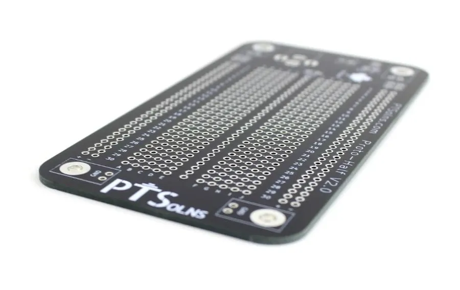
Protoboards, also sometimes referred to as perfboards or prototyping boards, offer a highly adaptable platform for constructing electronic circuits. Unlike breadboards that rely on a fixed grid, protoboards allow for customized component placement and wiring, providing greater flexibility in layout and circuit design. They are particularly useful when the final circuit design requires a non-standard configuration.
The defining characteristic of a protoboard is its array of holes, typically arranged in a grid pattern, that permit the insertion and soldering of electronic components. This physical structure allows for flexible circuit arrangement, enabling components to be positioned at locations best suited for efficient signal flow, heat dissipation, and the overall functionality of the device. Protoboards support a broad range of electronic components and can be readily customized to fit a specific design, making them an invaluable tool in the design process.
While often compared with standard breadboards, protoboards are designed for more permanent and custom circuit layouts. The direct soldering capability on a protoboard provides a robust and reliable connection that is far more stable than the temporary connections used in solderless breadboards. This makes protoboards ideal for projects where both flexibility in design and long-term stability of components are needed. They bridge the gap between the initial prototyping phase and the development of a final printed circuit board (PCB).
Furthermore, protoboards come in several configurations, including those with copper pads around each hole, and those with plated through holes, increasing their versatility in various electronic projects. The copper pads facilitate more robust solder joints, and the plated through holes provide additional mechanical stability when components are inserted. These options make protoboards a strong choice in both simple and complex prototype circuits.
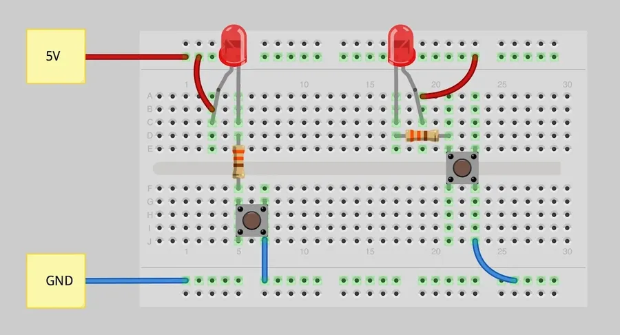
PCB Breadboard vs. Standard Breadboard: Key Differences
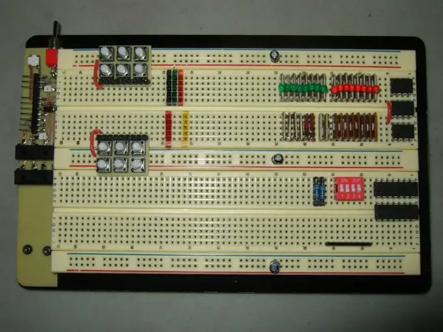
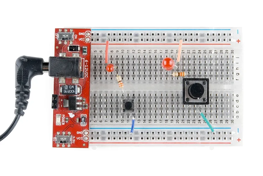
PCB breadboards and standard plastic breadboards serve the purpose of prototyping electronic circuits, but they differ significantly in their construction, durability, and suitability for various applications. A fundamental distinction lies in their physical structure; PCB breadboards utilize a rigid printed circuit board as their base, offering a more robust and often solderable platform, whereas standard breadboards use a plastic housing with internal metal clips designed for solderless connections.
| Feature | PCB Breadboard | Standard Breadboard |
|---|---|---|
| Base Material | Rigid PCB (often with solder pads) | Plastic with internal metal clips |
| Durability | High; can withstand soldering and repeated use | Moderate; prone to wear, loose connections and damage from heat or mechanical stress. |
| Connection Type | Solderable or solderless (depending on design), more permanent | Solderless; temporary connections using insertion |
| Signal Integrity | Generally better due to lower resistance and consistent conductor paths | Can have higher resistance and signal noise due to clip connections |
| Reusability | Reusable, but alterations may require desoldering | Highly reusable; easy to change connections |
| Component Stability | High; particularly with soldered components, excellent for secure component mounting | Moderate; prone to component movement and accidental disconnections |
| Typical Applications | More permanent prototypes, intermediate-term projects, circuits requiring stable connections, testing, and pre-production evaluation. | Temporary prototyping, testing simple circuits, educational purposes, quickly trying different circuit configurations |
| Cost | Higher initial cost, often more cost-effective over time with repeated use. | Lower initial cost, but may need to be replaced more frequently |
| Construction time | Soldering needed if using solderable types, time consuming if complex circuits are needed | Simple to construct complex circuit rapidly |
Transitioning from Breadboard to PCB: A Seamless Process
Moving from a breadboard prototype to a final PCB design is a crucial step in product development, and a PCB breadboard facilitates this transition by providing a stable intermediate platform. This process, when approached systematically, can significantly reduce design iterations and potential errors.
The use of a PCB breadboard offers several advantages during the transition phase. Firstly, it allows for a more accurate representation of the final circuit layout compared to a traditional solderless breadboard, reducing the risk of unforeseen issues arising from physical design changes. Secondly, it enables thorough testing and validation of component functionality and interconnection, leading to a more robust and reliable end product.
Here's a structured approach to facilitate the transition from a PCB breadboard to a finalized PCB:
- Design Refinement on the PCB Breadboard
After prototyping on a standard breadboard, transfer your design to the PCB breadboard. This allows for a more accurate representation of the final layout and reduces the impact of parasitic capacitance and inductance. - Component Selection and Validation
Re-evaluate component specifications based on performance observed on the PCB breadboard. Ensure components are suitable for the final PCB assembly with appropriate footprints for soldering. - Final Schematic Capture
Based on the optimized circuit on your PCB breadboard, create or update your schematic diagram. Ensure your schematic accurately captures the final design for future reference. - PCB Layout Design
Use your updated schematic to design the PCB layout with appropriate footprints for all selected components. Pay attention to trace impedance, component placement, and thermal management considerations. - Design Rule Check (DRC) and Verification
Thoroughly check your PCB layout against design rules and specifications. Use software tools to identify errors before fabrication. - PCB Fabrication and Assembly
Send your completed layout design to a PCB manufacturer. Upon receiving the manufactured PCBs, populate them with components according to your design and validation notes. - Testing and Validation of the Final PCB
Test your final PCB thoroughly to confirm functionality and performance aligns with your objectives. Make necessary improvements based on testing.
This systematic approach, coupled with careful documentation at every step, ensures a smoother transition from prototype to final product. PCB breadboards serve not only as a testing ground but also as a bridge, smoothing the development path and preventing significant errors further down the line.
Frequently Asked Questions about PCB Breadboards
This section addresses common queries regarding PCB breadboards, offering clear, concise answers to help you understand their use, benefits, and limitations in electronic prototyping and design.
- What exactly is a PCB breadboard?
A PCB breadboard combines the ease of use of a traditional solderless breadboard with the structural integrity of a printed circuit board (PCB). It provides a platform for prototyping electronic circuits where components can be interconnected, and in many designs, soldered for a more permanent assembly. - Is a PCB breadboard better than a standard plastic breadboard?
The 'better' choice depends on the application. Standard breadboards are excellent for quick, temporary prototyping. PCB breadboards, especially solderable types, offer improved durability, higher reliability, and better signal integrity, making them more suitable for longer-term or more sensitive projects. The more permanent and robust structure allows for a secure assembly that is less prone to accidental disconnections. Standard breadboards are better for initial testing and very temporary circuit design. - How can I transition from a breadboard prototype to a final PCB design?
Transitioning involves several key steps: First, ensure your circuit design works flawlessly on your chosen breadboard. Next, translate that design into a schematic diagram. Use this schematic to design the PCB layout in PCB design software. Confirm the design using various checks, then order your printed circuit board. Once the PCB arrives, solder the components, verify connectivity and you have your final PCB. - What is the primary difference between a breadboard and a protoboard?
While both are used for prototyping, they differ in layout and connection methods. Breadboards, typically solderless, feature internally connected rows and columns for easy component insertion. Protoboards, often PCB-based, provide a grid of independent pads or holes, allowing for more flexible layouts and soldering. Breadboards facilitate very quick prototyping and are often temporary. Protoboards can allow for more complex, more permanent, or easily modified circuits. - Can I solder components onto all types of PCB breadboards?
No, not all PCB breadboards are designed for soldering. Some PCB breadboards mimic the layout of solderless breadboards, these types are not generally designed for soldering. However, many, often referred to as solderable breadboards or protoboards, feature pads or plated-through holes that are specifically designed to be soldered onto to create a permanent connection. - What are the advantages of using a solderable PCB breadboard?
Solderable PCB breadboards offer superior mechanical stability, making the prototype more durable and reliable. They also enhance signal integrity, which is vital for high-frequency circuits. The ability to solder also allows for a more permanent connection. These characteristics make them suitable for projects that require long-term testing, or where the prototype is subjected to mechanical stresses. - Are there any limitations to using PCB breadboards?
Yes, PCB breadboards, particularly solderable types, are less flexible than solderless breadboards. Once components are soldered, modifications or reconfigurations can be more challenging and time consuming compared to a solderless breadboard. Furthermore, the complexity of the circuit design and component size may be limited by the breadboard's layout.
Choosing the Right PCB Breadboard for Your Project
Selecting the appropriate PCB breadboard is crucial for successful prototyping, influenced by project complexity, component needs, and desired permanence. This section guides users, from beginners to experts, in making informed decisions.
- Project Complexity
For simple circuits, a basic solderable PCB breadboard or a perfboard style will suffice. Complex projects involving numerous components or high-frequency signals may require breadboards with dedicated power rails and ground planes to minimize noise and improve signal integrity. - Component Types and Sizes
Consider the types and sizes of components you will be using. For through-hole components, standard solderable breadboards with 0.1-inch spacing are ideal. If your project includes surface-mount components (SMD), choose a board that provides appropriate pads or adapters for these components. Some boards may also include footprints for specific components, such as microcontrollers or voltage regulators. - Permanence Requirements
If the prototype is for temporary testing, a solderless breadboard with a PCB backing may be sufficient. However, for more durable and longer-lasting prototypes, solderable boards are the preferred choice. Solderable boards provide a more robust connection and are less prone to accidental disconnections. - Beginner vs Experienced User
Beginners often start with perfboard-style breadboards due to their ease of use and flexibility. Experienced users might prefer solderable options or specialized boards designed for specific tasks or component families. It is advised for both groups to consider future project requirements during the selection process.
| Feature | Solderable PCB Breadboard | Perfboard Style Breadboard | Solderless Breadboard with PCB Base |
|---|---|---|---|
| Durability | High; connections are permanent | Moderate; connections are semi-permanent | Low; connections are temporary |
| Complexity | Suitable for complex circuits; often includes power rails | Suitable for varied layouts; requires point-to-point wiring | Best for simple circuits; layout is fixed |
| Component Types | Supports both through-hole and SMD (with adapters) | Primarily for through-hole components; SMD can be challenging | Primarily for through-hole components |
| Ease of Use | Moderate; soldering skills required | Easy; less structured than solderable boards | Very easy; no soldering required |
| Signal Integrity | Good; offers low impedance and noise; with ground planes | Fair; may require extra care in wiring | Fair; susceptible to noise |
| Permanence | High; ideal for final prototype | Moderate; can be modified but not as permanent | Low; designed for temporary testing |
| Cost | Moderate to high | Low to moderate | Low |
Practical Tips for Using PCB Breadboards Effectively
Effective use of PCB breadboards hinges on careful planning and execution. These boards, designed for both prototyping and more permanent circuit construction, demand a methodical approach to maximize their benefits and avoid common pitfalls. This section provides actionable advice on layout, component placement, and troubleshooting techniques for PCB breadboards.
- Plan Your Layout
Before placing any components, sketch out your circuit and how it will physically map to the breadboard. Consider signal flow, power distribution, and component size. This pre-planning will save time and reduce errors during implementation. Start with power and ground connections, then continue with other components, ensuring a logical progression. - Prioritize Component Placement
Place critical components such as microcontrollers or sensors centrally on the board for easy access. Group related components together to minimize long and potentially noisy interconnections. For analog circuits, keep sensitive components away from noise-generating elements. Ensure components are properly aligned, especially for solderable types, to avoid future complications. Maintain enough space between components to facilitate soldering or future modifications. - Manage Power Distribution
Implement a clear power distribution scheme, typically using the edges of the board for voltage rails. Use thicker gauge wire or solder traces where higher currents are expected. Decoupling capacitors should be placed near power pins of integrated circuits to stabilize voltage and reduce noise. Ensure that power supplies are adequately rated for the loads presented by your circuit. - Maintain Clear Signal Paths
Route signals logically, avoiding sharp turns or unnecessary lengths. Use a systematic approach to trace your signal paths during the layout to make troubleshooting easier. If signals travel long distances, use shielded wire to minimize interference. Label each path with its function for easy future reference or modification. - Use Appropriate Wiring Techniques
Cut wires to the correct length to avoid clutter. Use color-coded wires to easily distinguish power, ground, and signals. Solder components carefully, ensuring solid connections but avoiding excess solder. Check connections with a multimeter to ensure they meet requirements. Avoid any short circuits by confirming components are placed within their corresponding pads. - Develop a Troubleshooting Process
When circuits don't function as expected, follow a logical troubleshooting approach. Use a multimeter to check voltages, currents, and continuity. Isolate the problem to a specific area and review all soldered joints for any weak connection. Verify component placements and values against your circuit diagram. It's beneficial to test each section of the circuit individually to pinpoint potential problems. Document your troubleshooting steps to expedite future diagnoses. - Document Your Work
Keep a detailed record of your breadboard setup, including component locations, wiring diagrams, and any modifications made. This documentation is invaluable for future use or when transferring the circuit to a permanent PCB. Photos of the physical implementation and circuit diagram can be used for quick reference.
PCB breadboards represent a significant leap in prototyping. Their ability to bridge the gap between temporary experimentation and more permanent circuit solutions makes them an essential tool for any electronics enthusiast or professional. By understanding their unique benefits and applications, you can use PCB breadboards to efficiently bring your electronic designs to life with a blend of flexibility and stability, ensuring a smooth path from initial idea to the finished project. The PCB breadboard is a gateway to innovative designs, enabling creators to bring their visions to life.