Unlocking High-Frequency Performance: A Deep Dive into Rogers PCB
In today's fast-paced world of technological advancements, the demand for high-performance electronic devices is ever-increasing. At the heart of these devices lie Printed Circuit Boards (PCBs), the unsung heroes that facilitate seamless communication between components. While FR-4 material is commonly used for PCBs, high-frequency applications often require specialized materials, that's where Rogers PCBs come in. This article will delve into the unique properties of Rogers PCB, exploring their superior performance and key advantages over conventional materials, ultimately showing how this technology underpins much of modern electronics.
What is a Rogers PCB?
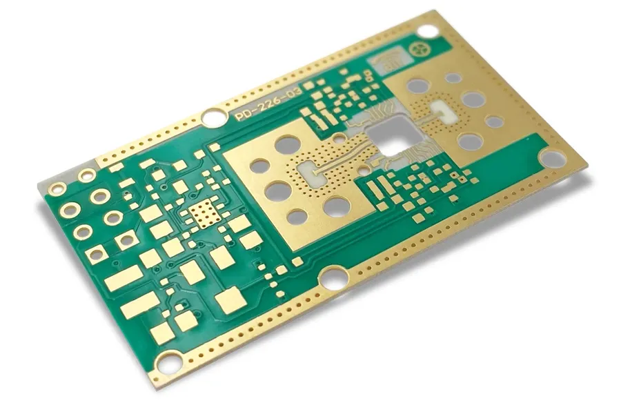
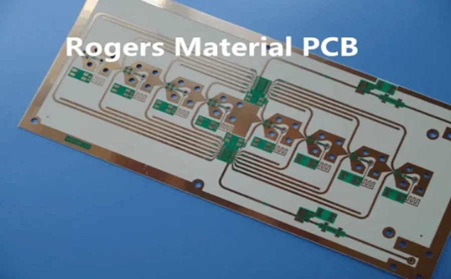
Rogers PCBs are a class of printed circuit boards that employ specialized high-performance laminates, distinct from the conventional FR-4 material. These laminates, manufactured by Rogers Corporation, are engineered to deliver superior electrical performance, particularly at high frequencies. This makes Rogers PCBs ideal for demanding applications requiring exceptional signal integrity and minimal signal loss.
Rogers PCB materials stand out from standard FR-4 due to their superior electrical and thermal properties, particularly at high frequencies. This section provides a detailed comparison of these two common PCB substrates across key performance parameters.
| Parameter | Rogers PCB | FR-4 PCB |
|---|---|---|
| Dielectric Constant (Dk) | Typically 2.2 - 10 (Precise Dk depending on specific Rogers material) | Typically 4.0 - 4.8 |
| Loss Tangent (Tan δ) | 0.0004 - 0.004 (Very low loss) | 0.018 - 0.025 (Higher loss) |
| Frequency Range | Optimal for High-Frequency, Microwave, and RF | Suitable for Low to Mid-Frequency |
| Thermal Conductivity | Relatively low, specific values dependent on the material type | Relatively low, typical values around 0.2-0.3 W/mK |
| Temperature Stability | High stability, Dk varies little with temperature | Moderate stability, Dk varies more with temperature |
| Moisture Absorption | Very low moisture absorption | Moderate moisture absorption |
| Cost | Higher | Lower |
| Application Suitability | High-speed digital, RF, microwave, aerospace, automotive radar | General-purpose, low-frequency applications |
Key Properties of Rogers PCB Materials
Rogers PCB materials are engineered for superior performance in demanding high-frequency applications, characterized by their exceptional dielectric properties. Unlike standard FR-4 materials, Rogers laminates exhibit significantly lower dielectric loss, maintain a stable dielectric constant across varying frequencies and temperatures, and deliver excellent electrical performance. These attributes are critical for signal integrity in high-speed, microwave, and RF circuit designs.
- Low Dielectric Loss
Rogers materials exhibit minimal signal loss, crucial for high-frequency applications where energy dissipation can severely degrade performance. This low loss is quantified by a low loss tangent (tan δ), ensuring minimal signal attenuation. - Stable Dielectric Constant
The dielectric constant (Dk) of Rogers materials remains consistent across a broad range of frequencies and temperatures. This stability is essential for predictable impedance control and minimal signal distortion, ensuring reliable circuit performance regardless of operating conditions. - Excellent Electrical Performance
Rogers materials are designed for high-frequency signal transmission with minimal signal degradation, ensuring reliable and predictable performance in demanding applications. - Temperature Stability
The electrical properties of Rogers materials show minimal variation with temperature changes. This is crucial for maintaining circuit stability and performance in environments with wide temperature fluctuations.
| Property | Description | Significance |
|---|---|---|
| Dielectric Loss (tan δ) | Measure of signal energy dissipation within the material. | Lower loss results in less signal attenuation, crucial for high-frequency signals. |
| Dielectric Constant (Dk) | Measure of a material's ability to store electrical energy. | Stable Dk ensures consistent signal propagation and impedance control. |
| Temperature Coefficient of Dk | Change in Dk with respect to temperature. | Lower coefficient leads to stable performance over a range of temperatures. |
| Thermal Conductivity | Measure of a material's ability to conduct heat. | Higher thermal conductivity is essential for heat dissipation in high-power applications. |
Rogers PCB vs. FR-4: A Detailed Comparison
Rogers PCBs distinguish themselves from standard FR-4 boards through their superior high-frequency performance, lower signal loss, and enhanced temperature stability. While FR-4 remains a cost-effective solution for less demanding applications, Rogers materials excel where signal integrity and high-frequency performance are paramount. This section will provide a detailed comparison between these two common PCB materials.
| Parameter | Rogers PCB | FR-4 PCB |
|---|---|---|
| Dielectric Constant (Dk) | Typically 2.2 - 10 (stable across frequencies) | Typically 4.5 - 4.8 (can vary with frequency) |
| Loss Tangent (tan δ) | Very low (0.001 - 0.004) | Higher (0.02 - 0.03) |
| Frequency Performance | Excellent up to millimeter-wave frequencies | Suitable for lower frequencies, limited above a few GHz |
| Temperature Stability | Superior, stable electrical properties across a wide temperature range | Less stable, properties can degrade at high temperatures |
| Moisture Absorption | Low | Higher, can affect electrical performance |
| Cost | Higher | Lower |
| Applications | High-speed digital, RF, microwave, aerospace, automotive radar, telecommunications | General-purpose electronics, lower-speed digital circuits |
Comparative Analysis: Rogers PCB vs FR-4
This table provides a focused comparison of key parameters between Rogers PCB and FR-4, highlighting the superior performance of Rogers materials in high-frequency applications. Rogers materials offer a lower loss tangent, meaning signals propagate with less energy dissipation, and a more stable dielectric constant across a range of frequencies and temperatures. This makes them ideal for sensitive applications like high-speed data transmission, radar systems, and RF circuitry. Conversely, FR-4, while more affordable, suffers from greater signal loss at higher frequencies and is less stable under varying temperature conditions, making it less suitable for advanced electronics.
Common Applications of Rogers PCBs
Rogers PCBs are integral components in a wide array of high-performance applications where signal integrity and reliability are paramount. Their unique material properties make them indispensable in industries requiring superior electrical performance at high frequencies.
- High-Speed Digital Circuits
In high-speed digital applications, Rogers PCBs minimize signal loss and maintain signal integrity. This is crucial for processors, memory interfaces, and data communication systems operating at gigahertz frequencies where signal degradation can severely impact system performance. - Microwave and RF Circuits
Rogers PCBs are exceptionally well-suited for microwave and RF circuits found in communication equipment, radar systems, and satellite applications due to their low dielectric loss and stable dielectric constant at high frequencies. These properties ensure efficient signal transmission with minimal signal attenuation. - Aerospace and Defense Systems
The robustness and high-reliability of Rogers PCBs make them crucial in aerospace and defense systems, including radar, avionics, and communication equipment. They withstand harsh environmental conditions and maintain performance under extreme temperature variations and vibrations, ensuring mission-critical reliability. - Automotive Radar
Advanced driver-assistance systems (ADAS) and autonomous driving technologies rely on Rogers PCBs for automotive radar applications. These PCBs provide the necessary high-frequency performance and signal integrity for accurate sensing and object detection, vital for the safety and functionality of modern vehicles. - Telecommunications Infrastructure
Rogers PCBs play a vital role in telecommunications infrastructure including base stations, antennas and networking equipment. The ability of Rogers PCBs to handle high frequencies and maintain low signal loss is crucial for the reliable and efficient transmission of data in modern communication networks.
Types of Rogers PCB Laminates
Rogers Corporation offers a diverse portfolio of high-performance PCB laminates, each engineered for specific applications and frequency ranges. These materials are broadly categorized into series, such as the RO4000 and RT/duroid, each possessing unique characteristics regarding dielectric constant, loss tangent, and thermal performance. Selecting the right laminate is crucial for optimizing the performance of high-frequency circuits.
| Laminate Series | Key Characteristics | Typical Applications |
|---|---|---|
| RO4000 Series | Low dielectric constant, stable performance, cost-effective | Automotive radar, wireless communications, power amplifiers |
| RT/duroid Series | Extremely low loss, high dielectric constant stability, excellent thermal properties | Aerospace and defense, high-frequency amplifiers, microwave circuits |
| RO3000 Series | PTFE composites, lower dielectric constant options, excellent stability | Microwave antennas, RF identification tags |
| TMM Series | Ceramic-filled thermoset polymers, Excellent dielectric constant and thermal stability | High power circuits, hybrid microcircuits |
The RO4000 series, known for its balance of performance and cost-effectiveness, is suitable for a wide array of applications, including automotive radar and wireless infrastructure. The RT/duroid series, on the other hand, is designed for more demanding high-frequency applications requiring extremely low loss and high stability, such as aerospace and defense systems. The RO3000 series provides a good balance of cost and performance in microwave applications, while TMM is excellent for high power and thermal stability applications. Understanding these distinctions is essential for making informed material choices for specific design needs.
Design Considerations for Rogers PCBs
Designing with Rogers PCB materials requires careful consideration of several key factors that differentiate them from standard FR-4 boards. These considerations primarily revolve around maintaining signal integrity at high frequencies, managing thermal performance, and adhering to specific fabrication requirements to ensure the board operates as designed. This section addresses these unique design aspects that are paramount to leveraging the full potential of Rogers materials.
Key design considerations for Rogers PCBs include:
- Impedance Control:
Precise impedance control is critical in high-frequency applications to minimize signal reflections and maintain signal integrity. Rogers materials' tight tolerances on dielectric constant allow for accurate impedance calculations, but variations in trace width, substrate thickness, and copper etching must be tightly controlled during the PCB design and manufacturing process. This precision is vital to optimize signal transmission and reduce loss. Special attention should be given to the stack-up and trace geometries to match the desired impedance. - Thermal Management:
While Rogers materials generally have good thermal characteristics, managing heat dissipation is still crucial, especially for high-power RF and microwave applications. Design techniques like thermal vias, heat sinks, and strategic component placement can help manage thermal issues. The thermal conductivity of the Rogers material itself should be a crucial consideration during material selection. - Fabrication Requirements:
Rogers materials, while offering superior electrical performance, can present unique fabrication challenges. They often require specialized equipment and techniques to handle. These may include laser drilling, routing, and controlled etching processes to handle the laminates. Adherence to the material-specific fabrication guidelines provided by Rogers is critical to avoid damage, ensuring the board performs as intended and maintaining its reliability. Fabricators with expertise in Rogers materials should be engaged to avoid any unforeseen fabrication errors. - Material Selection:
The correct selection of Rogers laminate is vital based on the operating frequency, temperature requirements, and the application-specific parameters. The wide range of Rogers laminates should be chosen carefully, balancing cost and performance. For instance, RT/duroid series may be suitable for high-frequency radar applications, while RO4000 series may be sufficient for high-speed digital systems. - Via Design:
Vias introduce impedance discontinuities in the transmission line, which can be a serious concern at higher frequencies. The size and plating of vias in Rogers PCBs should be carefully considered to ensure they do not significantly affect the impedance or cause signal loss. Blind and buried vias can be a consideration to minimize layer transitions and impedance mismatches. Careful simulation of via structures is essential to maintain signal integrity. - Surface Finish:
The choice of surface finish for Rogers PCBs also has design implications. Certain finishes may not be suitable for all Rogers materials or may create compatibility issues. Consideration should be given to the plating or finish requirements to reduce surface oxidation and contact resistance. Choosing the right finish can also ensure that the high-frequency properties of the board are maintained throughout its lifetime.
Frequently Asked Questions About Rogers PCBs
This section addresses common queries regarding Rogers PCBs, providing clear and concise answers to help you understand their properties, applications, and manufacturing considerations. These questions are frequently asked by users exploring high-frequency PCB solutions.
- What exactly is a Rogers PCB?
A Rogers PCB is a printed circuit board that utilizes specialized high-performance laminates manufactured by Rogers Corporation. These materials are distinct from standard FR-4 due to their superior electrical and thermal properties, particularly at high frequencies. They feature a low dielectric loss and a stable dielectric constant, which are crucial for high-speed and microwave applications. - What differentiates Rogers PCB from FR-4 PCB?
The primary difference lies in the core material. FR-4 is a common, cost-effective epoxy-based laminate, whereas Rogers materials are engineered for superior high-frequency performance. Rogers laminates exhibit significantly lower signal loss, a more stable dielectric constant over a wide range of frequencies and temperatures, and are more suitable for RF, microwave, and high-speed digital applications where signal integrity is paramount. FR-4, while versatile, is not suitable for high-frequency applications due to signal attenuation and performance instability at high frequencies. - What are the typical costs associated with Rogers PCBs?
Rogers PCBs generally cost significantly more than FR-4 PCBs. This higher cost stems from the specialized materials and manufacturing processes required to fabricate these boards. The exact cost depends on the specific Rogers laminate chosen, board size, layer count, and fabrication complexity. However, the premium cost is usually justified by the superior performance that Rogers PCBs provide in high-frequency applications, minimizing signal loss and ensuring signal integrity. - How does the manufacturing process for Rogers PCBs differ from that of FR-4 PCBs?
While the basic PCB manufacturing process is similar, Rogers PCBs require more precise handling due to the specific properties of the materials. Controlled impedance matching, low CTE of the materials, and the specific material stack-ups require extra attention during fabrication. This includes controlled etching parameters to maintain accurate conductor geometries, and careful control of temperature and pressure during the lamination processes. Additionally, specialized tooling may be needed to accommodate the unique material properties of the Rogers laminates. - Where can I source Rogers PCB materials?
Rogers PCB materials can be sourced from Rogers Corporation directly, or through their authorized distributors. It's important to verify the supplier's certification to ensure you're receiving genuine Rogers laminates. Additionally, many PCB fabrication houses are certified to process Rogers materials. - Which Rogers laminate is most suitable for my application?
The selection of the Rogers laminate depends heavily on the application's frequency, temperature range, and performance requirements. The RO4000 series is a versatile, cost-effective option for many high-frequency applications. The RT/duroid series is suitable for extremely high-performance applications. Carefully analyze the datasheets for dielectric constant, loss tangent, and temperature stability, and consult with a PCB fabrication specialist to ensure the best material is selected for your application. - Are there specific design considerations when using Rogers materials?
Yes, designing with Rogers materials requires careful consideration of impedance control, thermal management, and fabrication. Due to the low loss characteristics, precise impedance control is crucial. Due to the specific CTE, thermal management needs to be considered. Via design, plating, and other parameters also require additional attention to ensure the reliable and consistent performance of the final product.
The Future of Rogers PCB Technology

The future of Rogers PCB technology is focused on pushing the boundaries of high-frequency performance, efficiency, and sustainability. Ongoing research and development efforts are leading to advanced materials and manufacturing processes that promise even greater signal integrity and reduced environmental impact.
Current trends point towards several key areas of innovation:
- Advanced Material Development
Research is actively exploring new polymer blends and composite materials with even lower dielectric loss, improved thermal conductivity, and enhanced mechanical stability. This is vital for handling the escalating demands of higher frequencies and power densities. - Eco-Friendly Material Options
A growing emphasis on sustainability is driving the development of halogen-free and bio-based laminates. These materials aim to minimize environmental impact without compromising performance. - Integration with Advanced Manufacturing
Next-generation fabrication techniques like additive manufacturing (3D printing) and advanced etching processes are being explored to enable more precise and complex PCB designs with Rogers materials. This can lead to reduced material waste, faster turnaround times, and enhanced design flexibility. - Enhanced Thermal Management Solutions
With increasing operating frequencies comes the challenge of heat dissipation. Future developments focus on incorporating materials with high thermal conductivity and innovative cooling strategies directly into the PCB design for enhanced reliability and performance. - Integration of Smart Functionality
Rogers PCBs are expected to incorporate more integrated components, enabling smart functionalities like sensing, signal processing, and power management directly on the board. This will lead to more compact, efficient, and high-performing systems.
These innovations will continue to solidify the critical role of Rogers PCBs in high-performance applications, from next-generation telecommunications and radar systems to advanced computing and sensing technologies.
Rogers PCBs are indispensable for high-frequency electronics due to their superior performance characteristics. Understanding their unique properties and comparing them with traditional materials like FR-4 is crucial for engineers in selecting the best material for demanding applications. As technology continues to advance, Rogers PCB materials will remain at the forefront, driving the next generation of innovation in electronics. By adopting these materials, designers can create higher-performing devices, enabling more efficient and reliable electronic products.