Unlocking Tones: A Comprehensive Guide to Pedal PCBs
In the realm of music, the quest for unique sound is endless. Guitar effects pedals, with their ability to manipulate and transform tones, are crucial tools for musicians. At the heart of many of these pedals lies the pedal PCB (Printed Circuit Board), a seemingly simple yet complex component that brings these sonic dreams to life. This article dives deep into the world of pedal PCBs, providing a comprehensive guide for musicians, DIY enthusiasts, and anyone interested in building their own custom guitar effects.
Understanding the Role of a Pedal PCB
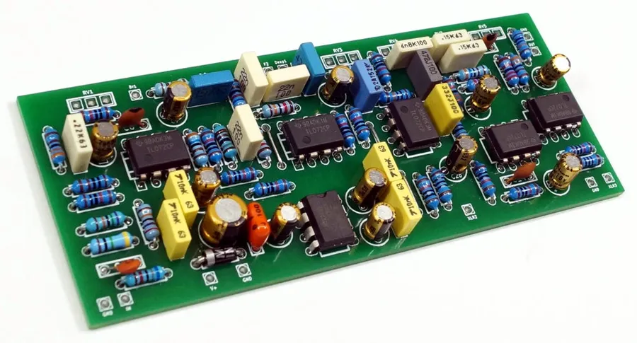
The Printed Circuit Board (PCB) is the foundational element within a guitar effects pedal, acting as the structural and electrical backbone that connects all electronic components. It provides a robust and organized platform to create a functional and reliable circuit.
Unlike point-to-point wiring, a PCB utilizes etched conductive pathways to link components like resistors, capacitors, integrated circuits (ICs), and transistors. These pathways, often made of copper, are precisely designed to route signals and power, ensuring the pedal's functionality.
The key functions of a pedal PCB include:
- Component Mounting
The PCB provides a stable and reliable platform for securely mounting electronic components, preventing them from moving or short-circuiting. - Electrical Connections
Etched copper traces on the PCB serve as conductive pathways, replacing messy point-to-point wiring and ensuring efficient signal and power transmission between components. - Circuit Organization
The PCB facilitates an organized layout that not only simplifies the construction process but also aids in troubleshooting and repairs. This organized approach leads to reliable and consistent performance of the pedal. - Heat Dissipation
The copper traces also help with thermal management, dissipating heat generated by components, which contributes to overall circuit stability.
In essence, the pedal PCB transforms an abstract circuit schematic into a concrete, functional object. It ensures both the electrical integrity and physical robustness needed for a reliable guitar effects pedal.
Key Factors to Consider When Choosing a Pedal PCB Supplier
Selecting the right PCB supplier for your guitar pedal project is crucial for ensuring the quality and reliability of your build. Several factors should be carefully evaluated, including the supplier's reputation, the quality of their PCBs, pricing structures, and the range of PCBs they offer.
Here's a detailed breakdown of key considerations:
- PCB Quality and Materials
The quality of the PCB is paramount. Look for suppliers that use high-quality materials like FR-4, a common substrate known for its electrical and mechanical properties. Verify the board thickness, copper weight, and the precision of the silkscreen and solder mask. These factors directly impact the board's durability and the ease of soldering. - Design Accuracy and Precision
The accuracy of the PCB design in relation to the schematic is essential. High-precision manufacturing ensures components fit correctly, and there are no trace routing errors that can compromise circuit performance. Confirm the supplier's ability to meet design specifications and tolerances. - Price and Cost Structure
While cost is a key factor, it shouldn't be the only determinant. Consider the overall value, balancing price with quality. Some suppliers offer volume discounts, which may be advantageous for larger projects, and some suppliers offer higher prices for small-batch runs. Assess transparency in pricing and avoid suppliers with hidden fees. - Range of Available PCBs
The supplier's selection should align with your specific project needs. Some suppliers specialize in specific types of pedal circuits (e.g., overdrive, fuzz, delay), while others offer a wider variety. Evaluate if the PCB selection matches your projects, and if there are readily available alternatives if the main choice is unavailable. - Supplier Reputation and Reliability
Investigate the supplier's reputation and reliability via online reviews, forum discussions, and recommendations from other builders. A reputable supplier with good feedback will be more likely to deliver on time, provide quality products, and have responsive customer support. Look for suppliers that offer transparent communication channels for tracking orders and addressing concerns. - Customer Support and Communication
Responsive customer support is essential, especially for addressing technical queries or issues related to your PCB order. Opt for suppliers that offer responsive and helpful support channels. Good communication practices can save significant time and frustration. - Shipping and Delivery Times
Timely shipping is crucial, particularly when working on deadlines. Check the supplier's shipping options, delivery times, and if they have reliable tracking information to reduce delay. Review feedback from other users concerning delivery timelines.
Top Pedal PCB Vendors: A Comparative Analysis
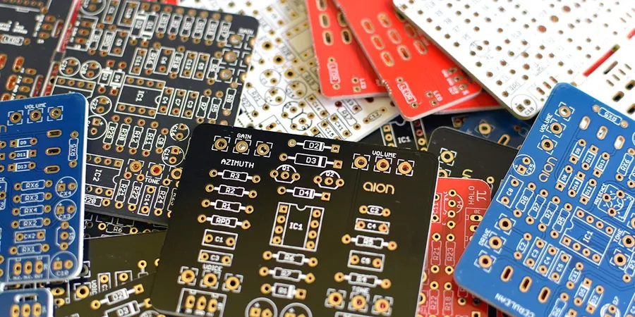
Selecting the right PCB vendor is crucial for achieving high-quality, reliable guitar effects pedals. This section provides a comparative analysis of leading PCB suppliers in the industry, focusing on their strengths, specializations, quality, cost, and design capabilities. We will examine PedalPCB.com, GuitarPCB, and Aion FX, which are widely recognized for their contributions to the DIY pedal-building community.
| Vendor | Strengths | Specializations | Typical Cost | Design Focus |
|---|---|---|---|---|
| PedalPCB.com | Extensive catalog, active community, well-documented projects. | Clones of popular effects, wide variety of circuit types. | Generally moderate, discounts for bulk purchases. | Emphasis on replicating existing circuits, ease of assembly. |
| GuitarPCB | High-quality boards, focus on accuracy and authenticity, good support. | Faithful recreations of vintage and boutique pedals. | Slightly higher, reflects focus on precision and component quality. | Focus on accurate reproduction of classic circuit designs. |
| Aion FX | Innovative designs, excellent documentation, advanced circuits. | Unique circuits, original effects, detailed instructions. | Moderate to higher, reflects complexity and quality of designs. | Emphasis on original circuits and unique tonal characteristics. |
Each of these vendors caters to different aspects of the pedal building community, from beginners looking for easy-to-assemble clones to experienced builders seeking innovative and complex designs. When choosing a vendor, consider your project needs, your budget, and desired level of design complexity to achieve your pedal building goals effectively.
DIY vs. Pre-made Pedal PCBs: Which is Right for You?

The decision between using a pre-made pedal PCB and designing your own hinges on your project's complexity, budget, and technical expertise. Pre-made boards offer convenience and reliability, while DIY designs provide unmatched customization and a deeper understanding of circuit design.
| Feature | Pre-made Pedal PCBs | DIY Pedal PCBs |
|---|---|---|
| Complexity | Simple assembly; less technical knowledge required. | Requires in-depth knowledge of circuit design and PCB layout. |
| Cost | Generally more expensive initially, but cost effective for low-volume builds. | Initial costs (software, tools) may be higher, but cheaper per board for high volume. |
| Customization | Limited to the existing design, minor component substitutions possible. | Fully customizable, allowing for unique effects and modifications. |
| Time | Faster assembly time, ideal for quick projects. | Time-consuming design and prototyping stages. |
| Learning | Provides a good platform to learn about the general function of a circuit, with low risk of failure. | Provides and excellent and comprehensive platform to learn circuit and PCB design. |
| Troubleshooting | Troubleshooting often involves component level problems, and usually easier to diagnose. | Troubleshooting requires debugging the schematic and the PCB layout, and may require more advanced equipment. |
Choosing the right approach depends on project requirements. Pre-made PCBs are ideal for beginners or those seeking a straightforward build process. DIY designs are best for advanced users aiming for unique circuits and who have the skills to implement them.
Essential Components for Building Your Pedal PCB

Constructing a functional effects pedal from a PCB requires a selection of essential electronic components. These components, when correctly assembled, form the circuit that shapes the guitar's signal, producing the desired effect. The following is a breakdown of these crucial components.
- Resistors
Resistors control the flow of current and are critical for setting gain, bias, and filtering. They come in various values (measured in ohms) and power ratings. Precision resistors are recommended for critical circuit points. - Capacitors
Capacitors store electrical energy and are essential for filtering, coupling signals, and creating timing circuits. Values are measured in farads (F), but more commonly microfarads (µF), nanofarads (nF), or picofarads (pF). Different types exist, such as ceramic, electrolytic, and film, each with specific characteristics. - Operational Amplifiers (Op-Amps)
Op-amps are the workhorses of many pedal circuits, providing gain and acting as buffers, filters, and comparators. Common op-amp ICs include the TL072, NE5532, and LM741, each with specific performance characteristics. - Transistors
Transistors are semiconductor devices used to amplify or switch electronic signals and electrical power. They are fundamental in many pedal designs, especially for gain staging and fuzz circuits. Bipolar Junction Transistors (BJTs) and Field-Effect Transistors (FETs) are common types used. - Diodes
Diodes allow current to flow in one direction and are used for clipping, rectification, and protection. Common types include silicon diodes (1N4148), germanium diodes (1N34A), and LEDs, which can introduce unique clipping characteristics. - Potentiometers (Pots)
Potentiometers are variable resistors used as controls for parameters like volume, tone, gain, and other effect settings. They come in various resistance values and tapers (linear or logarithmic). - Integrated Circuits (ICs)
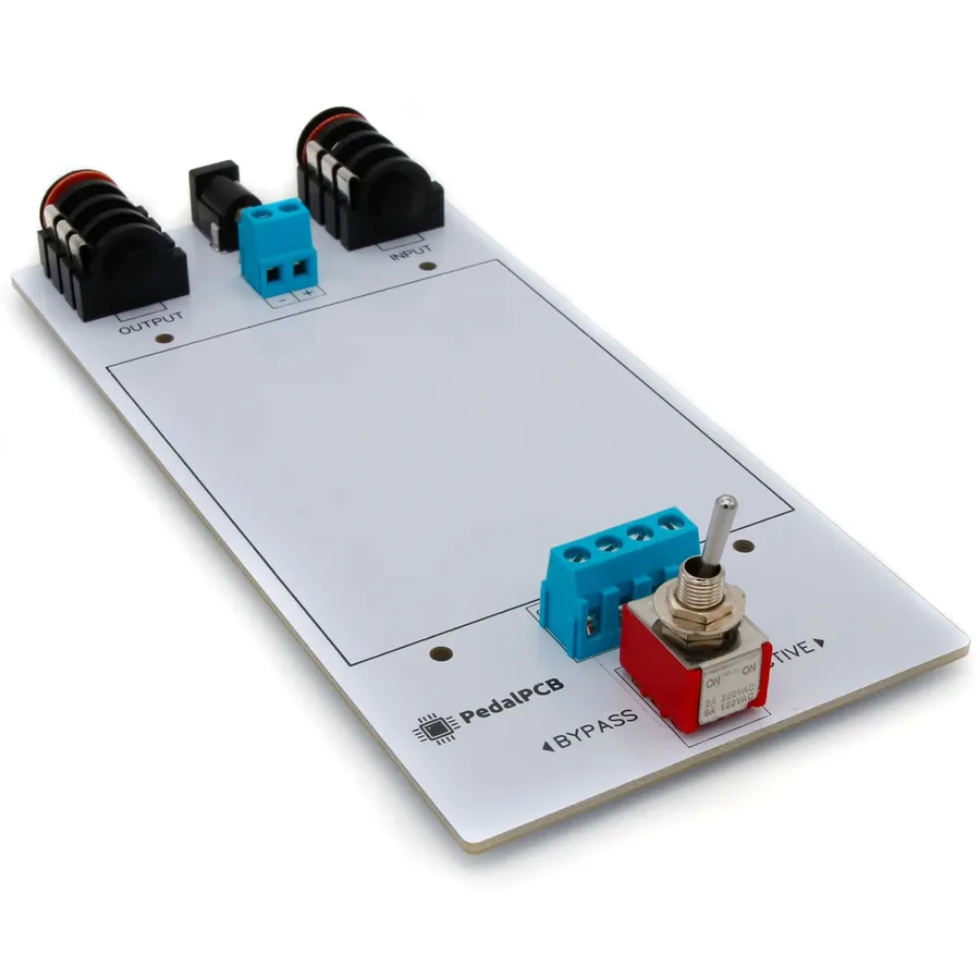
Beyond op-amps, other ICs can handle specific functions such as clock generation (for digital pedals), memory (for storing settings), or logic operations. These are generally specific to the pedal design. - Switches and Connectors
Footswitches are necessary for engaging the effect, while jacks provide input and output for the guitar signal and power. These need to be robust and reliable. - Power Supply Components
Components related to power regulation such as voltage regulators (e.g. 7805), capacitors, and diodes for filtering and stable power delivery to the circuit are needed, and are vital for the functionality of the circuit.
Step-by-Step Guide: Turning a PCB into a Working Pedal
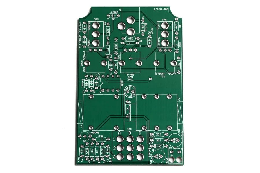
Transforming a bare pedal PCB into a fully functional effects pedal requires meticulous attention to detail and a systematic approach. This section provides a comprehensive, step-by-step guide, covering everything from component population to enclosure integration, ensuring a successful build.
- Prepare Your Workspace and Gather Tools
Before starting, ensure you have a clean, well-lit workspace. Gather all necessary tools, including a soldering iron with a fine tip, solder, wire cutters, wire strippers, tweezers, and a multimeter. Also, have the pedal PCB, electronic components (resistors, capacitors, ICs, etc.), and the chosen enclosure readily available. - Identify Components and Their Locations
Carefully review the PCB layout and schematic, and match each electronic component to its corresponding location on the PCB. Double-check the values of components, especially polarized ones like electrolytic capacitors and diodes, to ensure correct orientation. - Begin Populating the PCB
Start with the smallest components, usually resistors. Insert each component into its designated holes, bend the leads slightly to hold them in place, and then solder each lead to the PCB pad. Work methodically, moving from the smallest to the largest components, and double-checking each solder joint. - Soldering Best Practices
Ensure your soldering iron is heated to the correct temperature (around 350-400°C). Avoid using excessive heat, which can damage the components or the PCB. Use a small amount of solder to create a strong, shiny connection. A good solder joint should form a smooth fillet around the component lead and the PCB pad. - Install Integrated Circuits (ICs) and Transistors
Handle ICs and transistors carefully to avoid static discharge. Ensure they are oriented correctly according to the markings on the PCB and the component's datasheet. These components are often more temperature sensitive, so quick and precise soldering is critical. Consider using an IC socket if possible, for easier replacement or testing in the future. - Wiring External Components and Connections
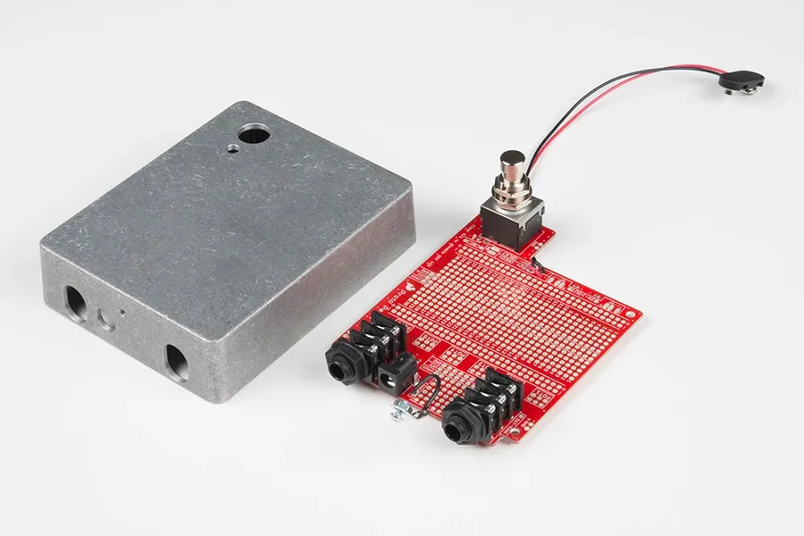
Once all the components are soldered onto the PCB, connect external wiring for power, input, and output jacks, as well as the footswitch and potentiometer(s). Use appropriate gauge wire and follow the schematic carefully. Secure the wires with solder and ensure they are routed neatly and don't interfere with other components or the enclosure. - Integrate PCB into the Enclosure
Carefully place the populated PCB into the enclosure, securing it with standoffs or mounting hardware. Ensure there is adequate clearance between the PCB and the enclosure to prevent any shorts. Connect the wiring from the enclosure to the appropriate points on the PCB. - Testing and Troubleshooting
Before closing up the enclosure, test the pedal thoroughly. Use a multimeter to check for shorts and proper power distribution. Connect the pedal to a guitar and amplifier and test the signal path. If any issues arise, consult the troubleshooting section. - Final Assembly and Testing
Once testing is complete, securely close the enclosure. Perform a final test to ensure everything is working properly, and enjoy your newly built guitar pedal!
Troubleshooting Common Issues with Pedal PCBs
Encountering issues while working with pedal PCBs is a common part of the DIY electronics experience. This section provides systematic troubleshooting advice for common problems such as shorts, incorrect wiring, and component malfunctions, ensuring a smoother building process.
- Short Circuits
A short circuit occurs when current flows along an unintended path with low resistance. Symptoms include overheating, non-functional circuits, and potential damage to components. Use a multimeter in continuity mode to check for shorts between power and ground traces, or between adjacent component pads. Visually inspect for solder bridges or stray wires that might be causing the short. - Incorrect Wiring
Incorrect wiring often results from misplaced or improperly oriented components. Verify component placement against the PCB layout diagram, and double-check polarity-sensitive components like diodes and electrolytic capacitors. A careful visual inspection and comparison with schematics can resolve most of the wiring issues. Also, confirm that all components are seated properly on the board and that there are no poor connections. - Cold Solder Joints
Cold solder joints occur when the solder does not properly adhere to the component lead or PCB pad. These joints appear dull and may cause intermittent or no signal passage. Reflow the solder joint with adequate heat, ensuring the solder flows smoothly around the connection. Use of flux can aid in a good solder joint. - Component Malfunctions
A malfunctioning component, such as a faulty op-amp or capacitor, can lead to erratic behavior or a non-functional pedal. Test suspected components using a multimeter or component tester to identify faulty parts. When using a multimeter, measure the resistance, capacitance, or voltage to see if the component is within its specifications. If a component is found to be faulty, replace it with a new one. - Intermittent Signals
Intermittent signal problems may result from loose connections, cracked solder joints, or failing components. Start by carefully re-soldering all connections, making sure that all solder connections are shiny and smooth. If the problem persists, examine all connections and components for any physical damage. Also, ensure that all cables or external wiring connections are well-fitted. - Grounding Issues
Proper grounding is essential for signal integrity and noise reduction. Ensure that all ground points are connected correctly. A poor ground connection can cause signal loss, noise, or a hum. Examine connections from your power supply to ground, as well as any grounding points on the PCB.
Frequently Asked Questions About Pedal PCBs
This section addresses common inquiries regarding pedal PCBs, providing clear and concise answers to assist both beginners and experienced builders in their projects. We cover a range of topics from component sourcing and design to troubleshooting, ensuring you have the information necessary for a successful build.
- Where can I source components for my pedal PCB?
Components for pedal PCBs can be sourced from various online retailers specializing in electronic components, such as Mouser, Digikey, and Tayda Electronics. Additionally, some pedal PCB vendors also offer component kits tailored to their specific board designs. Always ensure components meet the required specifications for optimal performance. For specialized components, vendor data sheets are authoritative sources for component specifications. - How do I read a schematic and layout for my Pedal PCB?
Reading schematics and layouts involves understanding electronic symbols and their connections. Schematics represent the circuit's logic using symbols for components, while layouts show their physical arrangement on the PCB. Resources such as online tutorials, datasheets for component datasheets, and books on electronics can help. Understanding these documents is key to a succesful pedal build. - What are some common mistakes to avoid when working with Pedal PCBs?
Common mistakes include incorrect component placement, shorts caused by solder bridges, using components with incorrect ratings, and neglecting to check the polarity of polarized components. Carefully review the PCB documentation and your work before powering on the circuit. Double-check your solder joints to avoid any potential shorts. - Can I modify the design of a Pedal PCB?
Modifying a PCB design is possible but requires a deep understanding of electronics and PCB design. If you wish to make modifications such as adding new features, changing tone shaping networks, or changing opamp configuration, a schematic and design software is needed. Proceed with caution, as alterations can impact circuit functionality and stability. Always consult reputable electronics resources and design tools when making modifications. - How do I troubleshoot a pedal that is not working after assembly?
Troubleshooting a non-working pedal involves a systematic approach, such as visually inspecting solder joints, checking for shorts and opens with a multimeter, verifying component values, and using an audio probe to trace the signal path. Reference the schematic to understand the expected behavior of each stage. Begin with a visual inspection, and move to electrical testing and finally signal tracing to identify the root cause. - Are there any safety precautions I should follow when working with Pedal PCBs?
Always follow safety precautions when working with electronics. Ensure your workplace is well-ventilated to avoid inhaling solder fumes. When soldering, use safety glasses to protect from solder splash. Be cautious when using power supplies. When dealing with power, safety is paramount to ensure not only your device is safe but that you are. - What tools are essential for building a pedal PCB?
Essential tools for assembling a pedal PCB include a soldering iron with a fine tip, solder, wire cutters, wire strippers, a multimeter, tweezers, and a desoldering pump or braid. A magnifying glass or a digital microscope is helpful for inspection. Having the right tools ensures a clean and efficient assembly process.
Advanced Techniques for Pedal PCB Design and Modification
Moving beyond standard pedal PCB assembly, advanced techniques in design and modification empower builders to craft truly unique effects. This section explores methods for tailoring existing designs and creating new ones to achieve specific tonal characteristics or functionalities, pushing the boundaries of what's possible with guitar effects.
- Component Value Tweaking
Experimenting with different resistor, capacitor, and potentiometer values around the main signal path can dramatically alter the gain, frequency response, and overall character of an effect. For example, increasing the value of a coupling capacitor can introduce more low-end frequencies into the signal, resulting in a fuller tone. - Op-Amp Swapping
Substituting op-amps within the circuit is a relatively straightforward method for changing tone and performance characteristics, as different op-amps have distinct gain, noise, and frequency response profiles. It's crucial to verify the pinout configurations to ensure a correct connection. - Modifying Clipping Stages
Alterations within the clipping stage, such as using different types of diodes or creating asymmetrical clipping, can produce subtle yet noticeable differences in distortion characteristics. Silicon diodes, germanium diodes, LEDs, or a combination, can be explored to change the amount and character of harmonic saturation. - Adding Tone Controls
Implementing a tone control network can offer additional shaping options, such as a Baxandall or James tone stack, enabling a player to adjust bass, mids, or treble response. Adding a tone control allows for further customization and flexibility. - Custom PCB Layout Design
When aiming for complete control over a circuit's layout, creating a custom PCB design becomes necessary. This process requires proficiency in PCB design software, knowledge of layout best practices, and understanding of trace impedance and signal routing. This allows for optimized performance and component placement.
| Technique | Description | Impact |
|---|---|---|
| Component Value Tweaking | Changing resistor, capacitor, or potentiometer values | Alters gain, frequency response, and tone |
| Op-Amp Swapping | Substituting different operational amplifiers | Modifies gain, noise, and overall performance |
| Clipping Stage Modification | Altering the diode types or configurations in the clipping stage | Changes the character of the distortion or overdrive effect |
| Tone Control Addition | Implementing passive or active tone control circuits | Provides adjustable frequency response |
| Custom PCB Layout Design | Designing PCB from scratch | Enables unique component placement and optimal performance |
The world of pedal PCBs opens up a vast playground for sonic exploration. Whether you're a seasoned DIY builder or a curious musician eager to delve into the technical side of tone, understanding pedal PCBs is crucial. From choosing the right supplier to mastering assembly techniques, the information provided in this guide empowers you to build, modify, and customize your unique guitar effects. Embrace the world of pedal PCBs and unlock the tones you've always dreamed of, transforming your sound one circuit at a time.